

1. Why a floating ball loads its own seat
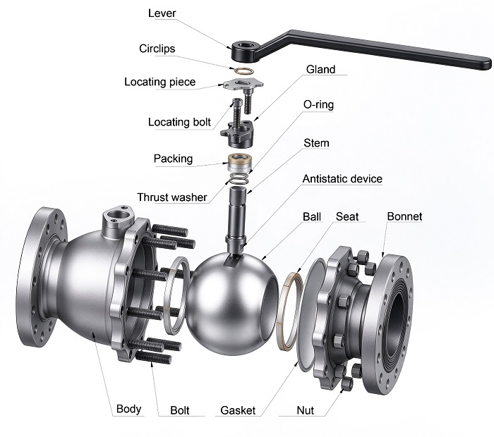
In a floating ball valve the ball rests between two seat rings and has no trunnion to hold it in place. Line pressure acting on the closed bore pushes the whole ball downstream until it presses on the downstream seat, and that movement is what generates the sealing force. The design is self energising, so sealing improves as differential pressure rises, and so does the torque needed to turn the ball. A floating valve is therefore light to operate at low pressure and progressively heavier at high pressure, which is the single most important fact behind actuator and gearbox selection.
2. Seat load follows pressure and bore area
Seat load is the product of differential pressure and the projected area of the bore. A 4 inch bore presents a projected area of 8,107 mm2, so a Class 150 valve at its 19.6 bar rating develops about 15.9 kN of seat load, while a Class 600 valve at 102.1 bar develops about 82.8 kN on the same bore. The ball does not respond to line size, it responds to bore and to the pressure behind it, which is why a 4 inch Class 1500 floating valve would carry more than 200 kN and why most suppliers stop offering the floating design well before that point.
| ASME class and rating | Seat load on a 4 inch bore | Break torque with PTFE seats |
|---|---|---|
| Class 150 at 19.6 bar | 15.9 kN | 100 to 150 Nm |
| Class 300 at 51.1 bar | 41.4 kN | 260 to 380 Nm |
| Class 600 at 102.1 bar | 82.8 kN | 520 to 760 Nm |
| Class 900 at 153 bar | 124 kN | 780 to 1,120 Nm |
| Class 1500 at 255 bar | 207 kN | 1,300 to 1,900 Nm |
The torque column is a range rather than a single value because packing friction, stem bearing quality and ball finish move the measured figure by 30 to 40 percent between two valves of identical size and class.
3. Break torque is not the torque you measure
Three numbers matter and they are routinely confused. Break torque is the peak required to start the ball moving from a seated, pressure loaded position. Running torque is what the operator needs to keep it moving, and on a PTFE seated floating valve it typically sits at 50 to 70 percent of break torque. Seating torque is the value at the end of travel, where the ball presses back into the seat. Actuator sizing works from break torque multiplied by a safety factor of at least 1.5, and sizing from running torque is the most common reason a pneumatic actuator stalls in the field.
4. Why the figure grows so fast with size
Seat load rises with the square of bore and the friction radius rises with bore, so break torque grows roughly with the cube of bore. Moving from a 2 inch to a 4 inch bore multiplies the pressure driven torque by about eight, which is why floating designs dominate from 1/2 to 4 inch while trunnion mounted designs take over above 6 inch. Temperature pushes the same number in a second way. PTFE softens and creeps above 120 C, so the seat needs a higher unit load to hold the same leakage class, whereas a metal seat at 650 C depends on spring load and lapped surfaces instead of polymer resilience.
5. Design levers that reduce torque
Seat ring width is the first lever. A narrower ring raises unit seating pressure and reduces contact area, so friction falls, at the cost of faster wear on dirty service. Ball surface finish is the second, since lapping to about Ra 0.4 keeps the friction coefficient low and protects the seat from scratching. Stem bearings, an anti friction coating on the stem and a stem diameter sized for torque rather than for pressure alone all remove parasitic losses. Spring loaded seats help most at low differential pressure, where the pressure driven load alone is too small to seat the ball, and they add little at high pressure where the self energising load already dominates.
6. Writing torque into the RFQ and the actuator order
Ask for break torque, running torque and the differential pressure at which each was measured, because a torque figure without a pressure is meaningless. State the fluid, the operating temperature, the seat material and whether the valve will sit closed for long periods, since break torque on a valve shut for a year can be 20 to 40 percent above the factory figure as the seat creeps into the ball. J-VALVES supplies floating and trunnion mounted ball valves across 1/2 to 56 inch (DN15 to DN1400) and ASME Class 150 to 2500, with PTFE, RPTFE, PEEK or metal seats, each unit seat tested at 1.1 times rated pressure and machined with an ISO 5211 pad so a gearbox mounts without an adapter.
7. Frequently Asked Questions
How is floating ball valve torque calculated?
Start from seat load, which is differential pressure times the projected bore area, then multiply by the friction coefficient and the seat radius. For a 4 inch Class 150 valve the seat load is about 15.9 kN, and with a PTFE friction coefficient near 0.1 the pressure driven torque lands around 80 Nm before packing and bearing losses are added.
At what size should I switch from floating to trunnion mounted?
Most specifications switch between 4 inch and 6 inch, and the trigger is torque rather than size alone. Because break torque grows with the cube of bore, a 6 inch floating valve at Class 600 can demand well over 1,000 Nm, which is where a trunnion design with a supported ball and much lower seat load becomes the cheaper total solution.
Why is my actuator stalling when the valve opens?
The actuator was almost certainly sized on running torque instead of break torque. Break torque can be two to three times the running value on a metal seated valve, and it rises further after long shut-in periods as the seat creeps into the ball. Size on break torque at the maximum differential pressure, then apply a safety factor of at least 1.5.