
CHINA J-VALVES Offers Various High-quality I ndustrial Ball Valves
J-VALVES, a distinguished professional ball valve manufacturer rooted in China, takes pride in its extensive product portfolio. Our offerings span a wide range, including trunnion-mounted ball valves, floating ball valves, high-temperature ball valves, high-pressure ball valves, metal-sealed ball valves, ultra-low temperature ball valves, DBB ball valves, Three-way And Four-way Ball Valve, and fully welded ball valves. Each product is a testament to our commitment to precision engineering and reliable performance. Meticulously crafted, they are designed to not only meet but exceed the most stringent industrial demands, ensuring stable operation even under extreme conditions. This enables us to provide our clients with high-value services and makes our valves widely sought-after in industries.
Product Category
Contact Us


Pressure Class: ASME Class 150 to 2500
Body Material: WCB, LCC, CF8M, CF3M, A105 forged
Body Style: One piece top entry
Ball & Stem: CF8M or F316 with ENP coating
Seat Material: PTFE, RPTFE, PEEK or metal
End Connection: Flanged RF / RTJ, butt weld
Operation: Gear, pneumatic or electric actuator
Maintenance: In line, through the top cover
Design Standard: API 6D / ISO 14313
Test Standard: API 598, API 607 fire safe
Options: Sealant injection, cavity relief, extended stem
-
TOP BALL VALVE
-
J-VALVES
Overview of the J-VALVES Top Entry Trunnion Mounted Ball Valve
The J-VALVES top entry trunnion mounted ball valve  uses a one piece body with a top entry bonnet, so the bolted body split flange is removed from the pressure boundary. The ball, stem, and seat assembly are installed and removed through the top cover, which also serves as the field service access for in line maintenance. Sizes cover 1 inch to 36 inch (DN25 to DN900) with pressure classes Class 150 to Class 2500 (20 bar to 420 bar). The design is built for pipeline service where the valve must stay in the line during seat or seal replacement. A spring loaded seat provides bidirectional sealing on both the upstream and downstream sides. Body cavity relief and a drain connection are fitted as standard to control trapped pressure. This construction suits transmission pipelines and process plants with limited shutdown windows. For operators, in line maintainability means a seat change does not require cutting the valve out of the pipeline.
Design and Construction
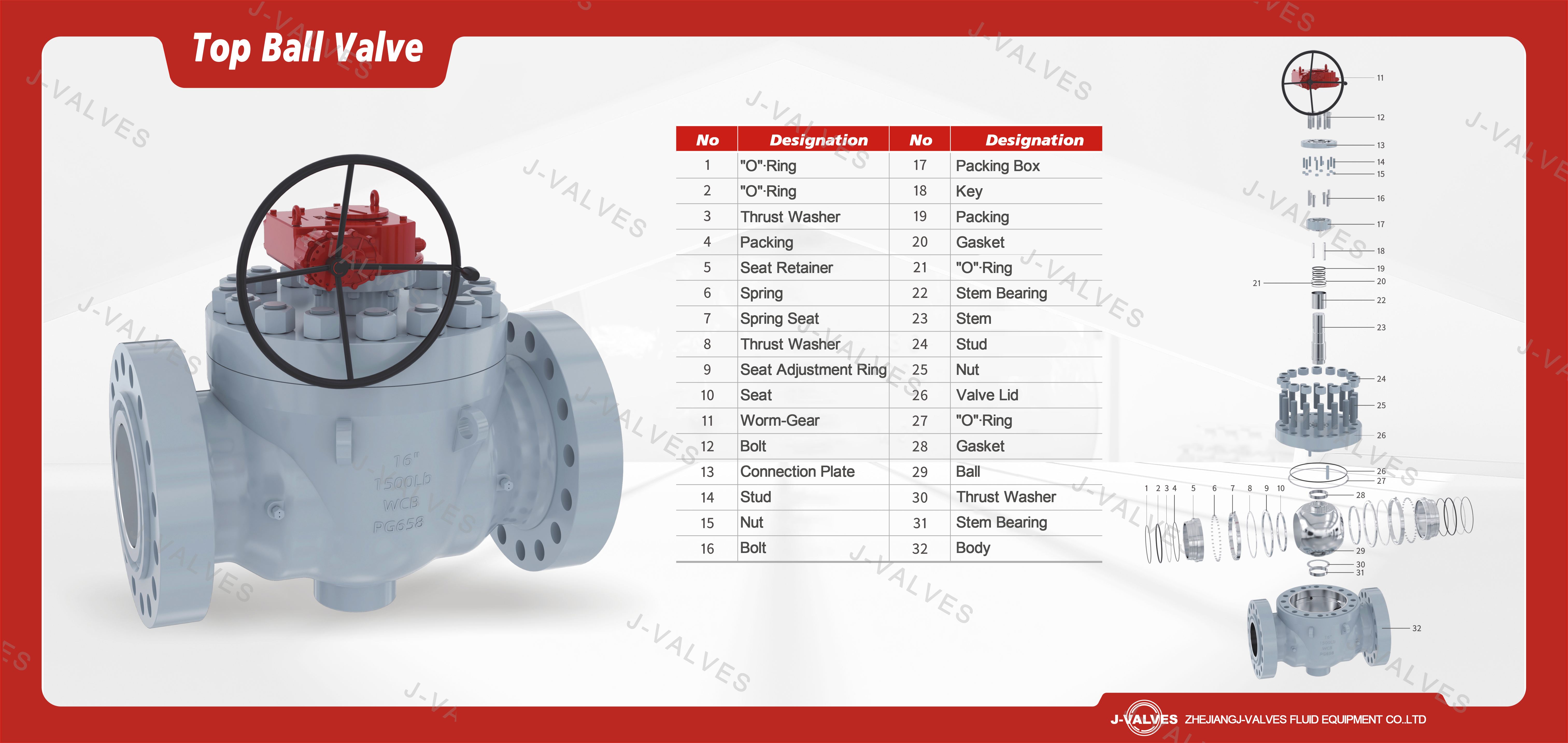
The defining feature of this valve is the one piece body. In a conventional split body trunnion valve, the body is bolted at a horizontal mid flange that sits inside the pressure boundary; every opening of that flange exposes a second body seal that must be reseated and proven leak tight. By casting or forging the body as a single piece and moving the service opening to the top, the mid flange is eliminated from the pressure envelope. The only body seam that must hold line pressure is the bonnet joint at the top, and that joint is outside the main through flow path.
The ball and stem form a single cartridge that is lowered into the body from above. Trunnion support means the ball is held at two bearing points rather than hanging on the stem, so the stem sees little thrust load even at Class 2500 (420 bar). Seats are spring loaded so they follow the ball as it wears and as temperature changes move the parts. The spring force pushes the seat ring against the ball on both sides, giving bidirectional sealing without depending on line pressure direction.
A body cavity relief connection is provided so that if trapped fluid heats and expands, pressure in the cavity can be vented before it reaches the bonnet seal. A drain connection at the cavity bottom supports safe de pressurization and cleaning during maintenance. The stem is equipped with a fire safe graphite packing stack below the primary packing to retain sealing if the soft packing burns away, supporting API 607 compliance.
Material Options
Material selection follows the service fluid, temperature, and the risk of sulfide stress cracking. The body is offered in carbon steel WCB and low temperature carbon steel LCC for general and cold service, in stainless CF8M and CF3M for corrosive duty, and in forged A105 for demanding service. The ball and stem use CF8M or forged F316 with ENP for erosion and galling resistance. Seats can be PTFE for clean service to around 200 degree C, RPTFE for improved creep resistance, PEEK for higher temperature and chemical duty, or metal to metal for abrasive or fire safe applications.
The table below lists the standard and optional materials for each wetted component.
| Component | Standard Material | Optional Upgrade | Service Notes |
|---|---|---|---|
| Body | WCB / LCC | CF8M, CF3M, forged A105 | Carbon steel for ambient and low temperature; stainless for corrosive line media. |
| Ball and stem | CF8M with ENP | F316 with ENP | ENP surface resists erosion, galling, and seat wear at cyclic duty. |
| Seat | PTFE | RPTFE, PEEK, metal to metal | Soft seats to 200 degree C; metal seat for abrasion and fire condition. |
| Body seal | PTFE / Graphite | Metal energized | Static seal at bonnet joint; graphite for high temperature. |
| Stem packing | PTFE chevron | Graphite fire safe stack | Primary seal; graphite layer retains seal per API 607. |
| Bonnet studs and nuts | A193 B7 / A194 2H | B8M, L7M | Bolted joint outside main flow; selected for temperature. |
| End connection | Flanged RF / RTJ | Butt weld | RF and RTJ per ASME B16.5 / B16.47; weld ends per ASME B31.3. |
For sour service the material can be supplied to NACE MR0175 / ISO 15156 with hardness control on the trim. Material certificates are issued as EN 10204 3.1 for the pressure retaining parts.
Technical Specifications
Standard ranges for the one piece top entry construction are listed below.
| Item | Value |
|---|---|
| Size | 1 inch to 36 inch (DN25 to DN900) |
| Class | Class 150 to 2500 (20 to 420 bar) |
| Body | One piece, top entry bonnet |
| Body material | WCB, LCC, CF8M, CF3M, A105 forged |
| Ball and stem | CF8M / F316 with ENP |
| Seat | PTFE, RPTFE, PEEK, metal |
| Seat action | Spring loaded, bidirectional |
| Ends | Flanged RF / RTJ, butt weld |
| Operation | Gear, pneumatic, electric |
| Temperature | minus 46 to 200 degree C |
| Standards | API 6D, ISO 14313, ASME B16.34 |
| Test | API 598, API 607 |
Optional items include metal seat, grease injection, and extended stem.
Standards and Compliance
Designed as an API 6D top entry valve, the unit follows API 6D and ISO 14313 for pipeline service, with shell and seat testing to API 598. Fire safety follows API 607, with a graphite stem pack and metal to metal secondary seat contact that holds after the soft seat is burned. Sealing performance can be verified to ISO 5208 where a tighter leakage class is specified by the purchaser.
Flange dimensions follow ASME B16.5 and ASME B16.47, face to face follows ASME B16.10, and wall thickness is checked against ASME B16.34. Pipeline installation is covered by ASME B31.4 for liquid and ASME B31.8 for gas. Sour service materials meet NACE MR0175 / ISO 15156 with controlled hardness on the trim.
The list below shows how each documented requirement is met and what is supplied with the order.
| Requirement | Standard | Supplied |
|---|---|---|
| Design and manufacture | API 6D / ISO 14313 | Design file and data sheet |
| Pressure boundary | ASME B16.34 | Wall check record |
| Shell and seat test | API 598 | Test report with torque record |
| Fire test | API 607 | Fire safe design statement |
| Flange and F2F | ASME B16.5 / B16.10 | Dimensional report |
| Sour service | NACE MR0175 / ISO 15156 | Material cert EN 10204 3.1 |
| Low temperature | BS 6364 | Material cert and test note |
Manufacturing Process
J-VALVES operates its own plant in Wenzhou, Zhejiang, China, covering casting mold and pouring control, CNC machining, assembly, hydrostatic and seal testing, torque measurement, coating, and export packing. The one piece body starts as a casting or forging depending on the grade: WCB and LCC are sand cast, CF8M and CF3M are cast to controlled chemistry, and A105 is supplied as a forging. Casting molds are controlled for gating and riser design so the body wall meets ASME B16.34 thickness after machining.
Rough machining removes the casting skin, then CNC centers bore the seat pockets, bonnet flange, and stem hole to hold the seat concentricity and the stem to bonnet alignment. Trunnion bearing seats are machined in the same setup to keep the ball axis true. After machining, the body and bonnet go through cleaning and inspection before assembly. The ball is machined and the ENP coating is applied to CF8M or F316, then ground to the seat fit tolerance.
Assembly builds the spring loaded seat, ball, stem, and bonnet joint in a controlled sequence, and the actuator mounting pad is machined to ISO 5211 so gear, pneumatic, or electric drives fit without modification. The single casting removes a mid flange to match, avoiding a common leakage path at the pressure boundary.

Quality Control and Testing
J-VALVES applies an eight step control sequence: incoming material, machining dimension, assembly and function, shell strength test, seal test, non destructive testing and hardness recheck, coating and marking, and final inspection with the document package. The shell strength test uses hydrostatic pressure at 1.5 times the pressure class, for example 225 bar for Class 150 (PN20) and 375 bar for Class 2500. The seat seal test is done at 1.1 times the class with air or gas, and leakage is recorded per API 598. Fire testing follows API 607 to confirm the valve holds after the soft seat is removed by fire.
The steps below are applied in order, and each is recorded in the test report that ships with the valve.
| Step | What Is Checked | Standard or Acceptance |
|---|---|---|
| Incoming material | Heat number, chemistry, hardness | EN 10204 3.1 material certificate |
| Machining dimension | Bore, seat pocket, flange face | Per drawing and ASME B16.5 |
| Assembly and function | Ball turn, torque, stem align | Torque record in test report |
| Shell strength | Body and bonnet at 1.5x class | No visible leak, no permanent set |
| Seat seal | Upstream and downstream seats | API 598 leakage class |
| NDT and hardness | Weld and trim hardness | Per procedure, hardness log |
| Fire test | Secondary metal seat after fire | API 607 hold requirement |
| Coating and marking | Paint, tag, body mark | Per order specification |
| Final inspection | Documents, packing list | Full package before shipment |

Paint Testing

PMI-TESTING
 Dimension Inspection
PT-TESTING

Pressure-Testing-Equipment
Applications and Industry Service
The top entry trunnion ball valve is used where a pipeline cannot be taken out of service for a simple seat change. Oil and gas transmission lines, product terminals, and tank farm manifolds rely on this pipeline ball valve because it stays in the line during maintenance. In these services a single unplanned shutdown can cost more than the price difference between a side entry and a top entry valve.
Process plants use the valve for feed, recycle, and utility streams where the spring loaded seat ball valve keeps a tight shutoff under thermal cycling. The bidirectional seat means the valve seals with flow in either direction, which suits lines that reverse or that are pigged from both ends. Slurry and abrasive duty can be fitted with metal seats and optional grease injection to extend service between overhauls.
Cryogenic and low temperature duty to minus 46 degree C uses the LCC body with the cavity relief and drain as standard, supporting safe isolation on LPG and similar services. For offshore and remote sites the in line maintainable ball valve reduces the spare valve count because the same body is serviced rather than replaced. Power and utility services use the valve on cooling water and auxiliary lines where reliable shutoff limits unplanned outage.
Installation, Operation and Maintenance
The one piece body is installed like any trunnion valve: align the flange or weld ends to the pipeline, support the weight for sizes above 24 inch (DN600), and set the actuator on the ISO 5211 pad. Because there is no body mid flange, the only joint that needs line pressure integrity at installation is the bonnet, which is already proven at the factory.
In line maintenance is the main reason to choose this valve. When a seat starts to leak, the line is isolated and depressurized, the top bonnet is removed, and the ball and seat assembly is lifted out vertically. The seat, body seal, and stem packing are replaced, the ball is inspected, and the bonnet is reset and retested. On a 12 inch Class 600 valve this trunnion ball valve maintenance is completed within a day, and the valve never leaves the pipeline.
Routine checks include verifying the cavity relief is clear, confirming bonnet bolt load, and watching the stem area for any packing weep. Optional grease injection lets the operator pass sealant to the seat if fine particles reach the sealing face between overhauls. The spring loaded seat needs no line pressure to seal, so the valve holds during isolation when both sides are at atmospheric pressure. Gear, pneumatic, and electric actuators share one pad, so a failed drive swaps without disturbing the body.

How to Specify and Order
To order the correct valve, specify the nominal size from 1 inch to 36 inch (DN25 to DN900), the pressure class from Class 150 to Class 2500, the body material, the seat type, and the end connection. State whether flanged RF or RTJ or butt weld is required, and name the operation: gear, pneumatic, or electric. If the line is sour, low temperature, or fire safe, mark the applicable standard so the trim and packing are selected accordingly.
J-VALVES accepts standard specifications with a minimum order of one piece, and standard items ship in 2 to 4 weeks. The delivery package includes an EN 10204 3.1 material certificate, a dimensional report, a test report with the torque record, a coating report, and a packing list. Export packing uses a wooden case with the bore plugged and the flange faces protected. Third party inspection can be arranged on request. For a quote, send the line condition and the data sheet so the seat and body seal are matched to the fluid and temperature.
About Top Entry Trunnion Ball Valve FAQ
Q: Can a top entry ball valve be repaired without removing it from the pipeline?
A: Yes. After the line is isolated and depressurised, the top cover is unbolted and the ball and seat assemblies are lifted out vertically. Seats, body seals and stem packing can be replaced and the valve retested with the body still bolted into the pipeline.
Q: Is a top entry valve more expensive than a side entry valve?
A: The up front cost is usually higher because the body is a single casting or forging and the internal parts are assembled through the top. The saving comes at the first maintenance event, when the valve does not have to be cut out, and from the removal of the bolted body joint from the pressure boundary.
Q: Does the top entry design use the same seats as a side entry valve?
A: The seat concept is the same, spring loaded with upstream and downstream sealing, but the seat and seal parts are specific to the top entry body. J-VALVES supplies spare seat and seal kits with the valve so the parts are available when maintenance is due.
Hot Products


News
Floating Ball Valve Applications: Working Principle, Selection Guide & Typical Services
Learn how a floating ball valve works, where it's used in oil & gas, chemical and offshore service, and how to choose between a floating and a trunnion ball valve.
Read More
Trunnion Mounted Ball Valves in Offshore Service: How Fixed-Ball Design Handles FPSO, Subsea and High-Pressure Duty
Trunnion ball valves for offshore service: how fixed-ball design manages FPSO, subsea and high-pressure duty, plus material, standard and RFQ selection tips.
Read More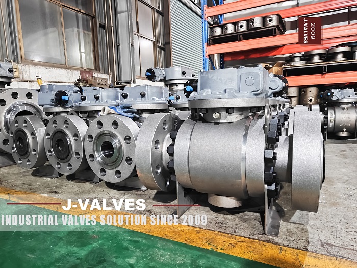
Inside The Valve Factory: 3PC Trunnion Ball Valve Manufacturing
Step‑by‑step factory tour of 3‑piece trunnion mounted ball valve production. Manufactured per API 6D, for oil & gas, chemical high‑pressure pipeline projects. Contact J‑VALVES for quotes.
Read More
Factory 3PC Trunnion Ball Valves Show Professional Manufacturing Capability
I. Mass‑Production Real‑Scene Shows True Industrial Valve CompetenceIn J‑VALVES manufacturing workshop, large quantities of finished 3‑piece (3PC) trunnion‑mounted ball valves are neatly stacked on wooden pallets, with completed coating and protected flange ends, real‑life deliverable goods for larg
Read More