


The valve that failed its closing test had not worn out. A 10 inch Class 300 trunnion ball valve on the brine line from a separator had been in service for fourteen months and had cycled perhaps two hundred times. When the plant tried to isolate the line for a pump change, the ball stopped about eight degrees short of the seat and the actuator stalled against it. The seat was undamaged. The ball was not eroded. A shell of amorphous silica roughly 1.2 millimetres thick had grown on the upstream face of the ball and on the seat ring, and the two coated surfaces were meeting deposit to deposit instead of metal to metal. The valve had been converted, quietly and without anyone noticing, from an isolation device into a flow restriction.
Geothermal is unusual among the services a ball valve meets because the damaging agent is not in the fluid at the point where the valve is bought. Silica is dissolved in the brine at the wellhead and stays dissolved for as long as the brine stays hot and pressurised. It becomes a solid only after the brine cools, and the place where brine cools is the pipe, the flange, the cavity and the seat pocket of whatever valve is standing in the line. This article works through that mechanism, then through the two other attacks that arrive with it, chloride stress corrosion and calcite at the flash point, and ends with the practical measures that keep a geothermal valve operable for a decade rather than two years.
1. What geothermal brine is, and the numbers that matter
Conventional hydrothermal brine is ground water that has equilibrated with hot rock. Depending on the field it is anything from a dilute 5,000 milligrams per litre sodium chloride solution to a hypersaline broth above 250,000 milligrams per litre, and it carries silica, calcium, potassium, bicarbonate, dissolved carbon dioxide, hydrogen sulphide and traces of arsenic, boron and mercury. A flash plant takes it at 200 to 320 degrees C and 15 to 80 bar, drops the pressure in one or two stages to produce steam, and reinjects the spent brine. A binary plant keeps it liquid all the way and gives its heat to a working fluid in a heat exchanger at 100 to 180 degrees C.
The valve specification is decided by four of those numbers and almost never by the ones that appear in the data sheet header. Temperature decides the seat material and the pressure class. Chloride decides the body material. Silica decides whether the valve will still move in two years. Hydrogen sulphide decides whether the trim has to meet a sour service hardness limit, and at 500 ppm in a 40 bar system the partial pressure is 0.02 bar, or 2 kilopascals, which is well above the 0.3 kilopascal threshold at which NACE MR0175 starts to apply. That last calculation is worth doing explicitly, because geothermal specifications frequently inherit a sour service clause from an oil and gas template without anyone checking whether it is triggered.
Parameter | Typical range | What it decides |
|---|---|---|
Wellhead temperature | 150 to 320 degrees C | Seat material, pressure class, bonnet length |
Wellhead pressure | 15 to 80 bar, up to 100 in deep fields | Body class; Class 300 loses about 12 percent of its 38 degree rating at 250 degrees C |
Total dissolved solids | 5,000 to 250,000 mg/L | Corrosion allowance, material group |
Chloride | 10,000 to 150,000 mg/L | Austenitic stainless excluded above about 60 degrees C |
Silica as SiO2 | 200 to 900 mg/L | Scale growth on every cooled surface |
Calcium | 200 to 2,000 mg/L | Calcite deposition at the flash point |
Dissolved CO2 | 0.2 to 5 percent by mass of the gas phase | pH rise on flashing, carbonate supersaturation |
Hydrogen sulphide | 10 to 500 ppm | Sour service hardness limit, material selection |
Non condensable gas | 0.3 to 5 percent by weight | Two phase behaviour at the seat, vacuum systems |
pH at wellhead | 4.5 to 6.5 | Carbon steel corrosion rate, titanium compatibility |
2. Silica has retrograde solubility, and that inverts the usual instinct
Most salts dissolve better in hot water than in cold, which is why a heat exchanger fouls on the hot side and a cooling tower does not. Amorphous silica behaves the other way round. Its solubility rises with temperature, roughly doubling for every 50 kelvin, so a brine that is saturated at 250 degrees C holds about 600 to 900 milligrams per litre, and the same brine at 100 degrees C can hold only about 350. Cool it and the difference has to go somewhere, and it goes onto the nearest surface as a glassy, hydrous, extremely tenacious deposit.
This is the single most important fact in geothermal valve selection, because it means that every element of the valve that is cooler than the bulk fluid is a deposition site, and the elements that are cooler are exactly the ones that have to move. A body at 250 degrees C loses heat through its insulation, its bonnet, its mounting bracket and its flange faces. The cavity between the ball and the body is a dead volume that exchanges heat slowly and holds brine for weeks. The seat pocket is a crevice with a still fluid column in it. All three sit a few tens of kelvin below the flow, and all three collect scale.
The rate is not dramatic on a daily basis and is relentless on an annual one. Field measurements on brine piping typically run from 0.05 to 0.5 millimetres a month on wetted steel, faster in low velocity zones and slower in the turbulent core, and the deposit that forms on a 250 degree surface is denser and harder than the fluffy material that forms in a pond. A millimetre of silica has a thermal conductivity of about 1.3 watts per metre kelvin against 45 for carbon steel, so the insulating equivalent of one millimetre of scale is roughly 35 millimetres of steel. In a heat exchanger that number is the whole economic argument for scale control. In a valve it is the argument for a geometry that cannot trap fluid.
There is also a mechanical consequence that is easy to overlook. Silica deposits do not grow evenly. They nucleate on scratches, on the boundary between the hard facing and the substrate, and on the seat contact band, and they grow as nodules. A nodule 1 millimetre high on the seat ring holds the ball off its seat by 1 millimetre, which for a Class V metal seat is the difference between passing and failing. The deposit does not have to be thick to break the valve. It has to be present where the two sealing surfaces meet.
3. Calcite forms where the pressure drops, which is inside the valve
The second scale is calcium carbonate, and it behaves on a different rule. Calcite solubility falls as temperature rises, so hot surfaces foul, but in geothermal the dominant driver is carbon dioxide. Wellhead brine is acidic because it carries dissolved CO2 at 15 to 80 bar. When the pressure drops at a flash stage, the CO2 leaves the liquid with the steam, the carbonic acid equilibrium shifts, and the pH climbs from around 5 to between 7 and 8 within seconds. At that pH and at 150 to 250 degrees C the brine is heavily supersaturated in calcium carbonate, and it deposits on the first surface it touches.
That surface is frequently the downstream side of the valve that did the flashing. A ball valve used to drop pressure in a geothermal line will collect a hard, cream coloured, adherent scale ring on the downstream seat and in the downstream bore, and because the deposit is brittle it spalls in flakes that then travel into the plant. The failure mode is not gradual loss of sealing. It is a valve that closes onto a flake and is then eroded by the leakage jet that the flake created.
The mitigation is the same as in any flashing service, which is to not flash across the ball. Put the pressure drop in a dedicated device with a hardened trim and a straight expansion path, and give the ball valve the job it is good at. Where the process cannot be arranged that way, the valve must be specified for two phase flow with a hard faced trim, a full port bore and a downstream body lined or overlaid to resist the jet.
The scale itself can be removed, but the methods are limited and unpleasant. Calcium carbonate yields to a modest acid wash, which is one of the reasons it is the lesser of the two problems. Amorphous silica does not respond to acid at all. It dissolves slowly in hot caustic at pH 10.5 to 11 and it yields to hydrofluoric acid, which no plant wants to handle on a live brine line. In practice silica is removed mechanically, with a scraper, a wire brush or a high pressure water jet, and the design should assume that this is what will happen and provide access for it.
4. Chloride decides the body, and temperature decides whether the chloride matters
Chloride stress corrosion cracking of austenitic stainless steel needs three things at once: a susceptible metallurgy, tensile stress and a chloride concentration above a threshold that falls as temperature rises. In a geothermal brine with 10,000 to 150,000 milligrams per litre of chloride at 200 to 300 degrees C, all three are present in abundance, and 316L is not a candidate material no matter how convenient it is. The threshold for practical purposes is around 60 degrees C at these concentrations, which means that even the cold end of a geothermal system is not a safe place for an austenitic body.
Duplex and super duplex are the next step up and they are genuinely better, but they are not unlimited. A 2205 body is a reasonable choice up to about 150 degrees C in moderate chloride brine and a poor one above 200 degrees C. A 2507 super duplex extends that to roughly 200 degrees C. Both depend on a ferrite austenite balance that must be verified on the finished casting, not on the heat certificate, because the balance shifts with section size and with the cooling rate after solution annealing. A 2507 body with 60 percent ferrite is a different material from one with 40 percent.
Titanium is widely used in geothermal and it is excellent where it is used correctly. Grade 2 tolerates high chloride brine to well above 250 degrees C and is immune to chloride stress corrosion. Its limits are elsewhere: it is attacked by reducing acids, so a brine at pH below about 3.5 with a significant hydrogen sulphide content is a risk, and it is susceptible to crevice corrosion in tight gaps at temperatures above 70 to 80 degrees C, which is precisely the geometry of a seat pocket. Grade 7, with a small palladium addition, raises the crevice threshold considerably and is the usual choice for severe brine. Titanium also galls and it cannot be used as a bearing surface against itself.
Carbon steel remains the workhorse, with a corrosion allowance and a hard faced or carbide coated trim. It fails by general thinning, which is predictable and inspectable, rather than by cracking, which is neither. A 6 millimetre allowance on a WCB body is normal for moderate brine, and the honest engineering position is that the body is a consumable scheduled for replacement in fifteen years while the trim is a consumable scheduled for replacement in three.
5. Why 250 degrees C removes most of the seat materials from the list
Seat material is where geothermal specifications most often go wrong, because the catalogue values are quoted at ambient and the service is at the top of the range. PTFE is rated to about 200 degrees C for continuous service, and even below that temperature it creeps under seat load in a way that relaxes the sealing force over months. Modified PTFE gains perhaps 20 to 30 kelvin. PCTFE is worse. PEEK is the best of the polymers, usable to about 250 degrees C continuous and 280 intermittent, but it is hard and notch sensitive, its thermal expansion is high, and it has to be designed with clearance rather than crush.
Above 250 degrees C the industry goes to metal, and metal comes with a contract attached. Zero leakage at a few tenths of a bar is not achievable with a ground ring against a ground ball, both surfaces have to be hardened, and the seat load has to be high enough to deform the contact band slightly on every closure. That is acceptable in geothermal because the pressure is high and the fluid is dirty. What is not acceptable is a specification that asks for a soft seat because the buyer is used to soft seats, and then discovers at the witness test that the only material that survives is a metal ring with a leakage class the purchase order never mentioned.
Seat material | Continuous limit | Behaviour in brine | Verdict for geothermal |
|---|---|---|---|
PTFE | 200 degrees C | Creeps under load, cold flow at the seat | Only in the cold end of a binary plant |
Modified PTFE | 210 to 230 degrees C | Better creep, same chemistry | Marginal above 180 degrees C |
PCTFE | 150 degrees C | Harder, lower temperature | Not suitable |
PEEK | 250 continuous, 280 short | Hard, notch sensitive, high expansion | Upper edge of binary and low flash duty |
Graphite and metal laminate | 400 degrees C | Handles scale poorly, leakage class lower | Usable, rarely chosen |
Metal to metal, carbide faced | 600 degrees C and above | Scrapes scale off the ball, Class IV or V | Standard choice above 250 degrees C |
Metal to metal, Stellite faced | 600 degrees C and above | Tolerates thermal shock better than carbide | Preferred where cycling is severe |
6. The cavity is a settling tank that is also a heat sink
In a trunnion mounted design there is a dead volume behind the ball, open to the bore while the valve is in service and sealed off from it once the ball turns. In clean service this is a design detail. In geothermal it is the failure site. Brine enters that volume while the valve is open, sits there while the valve is closed, loses heat through the body wall, and precipitates silica onto the ball, the seat carrier and the body bore. After a few hundred cycles the deposit has bridged the running clearance between the ball and the seat carrier, and the torque required to move the valve rises far beyond the clean figure.
Torque is where this stops being a maintenance annoyance and becomes a purchase order error. Take a clean 10 inch Class 300 metal seated valve breaking out at 1,200 newton metres across full differential. Add a silica shell on the ball and a scaled seat pocket, and the same body asks for 3,000 to 4,000, which is three times what the original actuator was told to expect. The plant then reports a seized valve, fits a bigger actuator, and repeats the whole failure on the new hardware a year later.
Four design measures address it, and all four are cheap at the point of order and expensive afterwards. Stand the valve with its stem pointing up and put the low point drain at the bottom, so that whatever settles can be drawn off instead of accumulating. Add a wash port into the cavity plus a drain valve, and use both as part of the isolation procedure rather than only at shutdown. Avoid body designs with large unswept cavities, since a cavity is a settling tank by definition. And size the actuator on the scaled torque with a factor of 1.5 to 2.0, checked at the minimum instrument air pressure and the minimum ambient temperature, which in a geothermal plant in winter can be well below freezing while the line is at 250 degrees C.
7. Flashing across the seat: 16 percent by mass, 28 times by volume
When a ball valve is asked to isolate a flashing stage it will, at some point in its travel, be the throttling device. The arithmetic is worth doing once. Saturated water at 40 bar has an enthalpy of about 1,087 kilojoules per kilogram. At 10 bar the saturated liquid holds 763 and the latent heat is 2,015, so dropping the pressure produces a vapour mass fraction of (1,087 minus 763) divided by 2,015, which is 0.16. Sixteen percent of the mass becomes steam, and because steam at 10 bar occupies about 0.19 cubic metres per kilogram against 0.0011 for liquid, the mixture occupies roughly 28 times the volume of the liquid that entered.
A seat gap sized for liquid therefore passes a mixture that must accelerate by a factor of 28, and it cannot, so it chokes. For a two phase mixture at these conditions the choked velocity sits somewhere between 20 and 40 metres per second, and the jet leaving the gap carries both the silica that has already come out of solution and the droplets that are about to. Wear rises with velocity raised to somewhere between 2.5 and 3, so going from 2 metres per second in the pipe to 30 at the seat multiplies the damage by several hundred. That is why a geothermal ball valve used as a throttle loses its seat in months while the same valve used only for isolation lasts years.
There is a thermal version of the same problem. A body at 250 degrees C that is suddenly exposed to cold water, from a hydrotest, a wash or a cold start, develops a surface thermal stress of several hundred megapascals because the surface contracts while the core does not. Carbon steel yields locally and then cracks in thermal fatigue after enough cycles. The design answer is a body with generous fillets, no sharp section changes, and a warm up procedure that brings the valve up with the line rather than after it.
8. Operating practice that actually extends life
Three operating habits decide whether the mechanical design gets a chance to work. The first is stroking. A geothermal isolation valve that is never moved will be immovable when it is needed, and the industry answer is a partial stroke on a fixed interval, monthly at minimum, with the torque recorded so that a trend exists. Breakout torque creeping upward is the first symptom of a cavity filling with scale, and it shows up months before the valve fails to close.
The second is velocity. Silica deposition is suppressed by shear, so a line that runs below about 1 to 1.5 metres per second will scale faster than one that runs at 2.5. But erosion of a carbon steel body with entrained solids becomes significant above 4 to 5 metres per second. The workable window is narrow, and it is one more argument for a full port ball valve rather than a reduced port one, because the full port bore keeps the velocity in the pipe at the pipe value instead of doubling it at the valve.
The third is flushing discipline at isolation. Before a valve is closed for maintenance, the cavity should be flushed with clean condensate or inhibited water and then drained, so that the brine does not sit in the dead volume for the duration of the outage. This costs fifteen minutes and one hose connection, and it is the difference between a valve that opens on the first attempt after a two week shutdown and one that has to be cut out.
9. What goes on the purchase order
Isolation valves in geothermal brine shall be trunnion mounted, full port and metal seated, in a bolted two or three piece body so that the trim can be renewed in place. Pressure class is read off the applicable pressure temperature table at the maximum wellhead temperature, not carried over from a cold rating. The pressure boundary is A216 WCB carbon steel carrying a 6 millimetre corrosion allowance on every wetted surface, or A995 5A super duplex where chloride exceeds 50,000 milligrams per litre and the temperature exceeds 150 degrees C, or titanium Grade 7 where chloride exceeds 100,000 milligrams per litre with a pH above 3.5 and a hydrogen sulphide partial pressure below 0.1 bar. Trim is A182 F6a or F55, tungsten carbide coated by HVOF to 300 to 400 micrometres, ground to 0.2 to 0.4 micrometre Ra, with a lapped contact band no wider than 2 millimetres. Any carbon or low alloy steel component in a stream whose hydrogen sulphide partial pressure exceeds 0.3 kilopascal is to comply with NACE MR0175 at 22 HRC maximum.
Bonnet length is chosen so that the packing runs below 200 degrees C at the maximum line temperature, and the gland is graphite with live loading. Two connections are mandatory: a wash port into the cavity, and a drain at the low point of the installed orientation. The body will be insulated on site, but the bonnet and the stem are to be left bare so that heat leaves upward rather than into the packing. Actuator sizing is on the scaled breakout torque with a 1.5 factor minimum, checked at minimum supply pressure and minimum ambient temperature, and the assembly is to include a partial stroke test function. Documentation with each valve: EN 10204 3.1, positive material identification on body, ball and trim, a ferrite check taken on the finished duplex casting, coating thickness and bond strength, a hardness survey, and a hydrostatic test made with water below 30 milligrams per litre of chloride, drained and dried immediately afterwards.
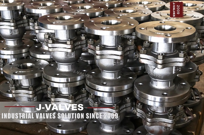
For reference, the geothermal scope leaves the J-VALVES works in bores from DN15 to DN1400, which is 1/2 inch through 56 inch, in ASME Class 150 to 2500, in carbon steel, duplex, super duplex, titanium and nickel alloy bodies, for service from minus 196 to plus 650 degrees C. Shell tests run at 1.5 times the cold working pressure and seat tests at 1.1 times, to API 598 or API 6D as the order requires, and HVOF carbide and Stellite overlays are applied and recorded in house. A complete data sheet gets a priced and drafted response inside three working hours, including the actuator torque calculation on the scaled condition rather than the clean one.
10. The rule that saves the most money
Geothermal valves fail for three reasons that look unrelated and are not: the brine cools where it should not, the pressure drops where it should not, and the material was chosen for the temperature on the data sheet rather than the chemistry in the pipe. Solve the first with geometry and heat, the second with process arrangement, and the third with an honest reading of the chloride and hydrogen sulphide numbers, and the ball valve does what it was designed to do. It sits in the line, cycles a few hundred times a year, and is still operable when the plant is decommissioned.
11. Frequently Asked Questions
Why does silica scale form on a geothermal valve but not in the brine itself?
Because silica solubility falls as temperature falls, which is the opposite of most salts. Brine saturated at 250 degrees C holds roughly 600 to 900 milligrams per litre of dissolved silica, and the same brine at 100 degrees C holds only about 350. Any surface cooler than the bulk fluid therefore becomes a deposition site, and the parts of a valve that are cooler are the body wall, the bonnet, the cavity and the seat pocket, which are also the parts that have to move. Deposition rates on brine piping typically run from 0.05 to 0.5 millimetres a month, faster in low velocity dead zones.
At what temperature does a geothermal valve stop being able to use a PTFE seat?
About 200 degrees C for continuous service, and rather less in practice because PTFE creeps under seat load and relaxes the sealing force over months. Modified PTFE gains 20 to 30 kelvin and PEEK reaches about 250 degrees C continuous, which puts it at the edge of binary plant duty but not of flashed brine. Above 250 degrees C the choice is metal to metal seating with a carbide or Stellite faced ball and seat ring, and that comes with a leakage class of IV or V rather than bubble tight, which has to be written into the specification before the witness test rather than argued about at it.
Is 316L stainless acceptable for a geothermal brine valve body?
No, above about 60 degrees C at the chloride concentrations found in geothermal brine. Chloride stress corrosion cracking needs a susceptible metallurgy, tensile stress and chloride, and a brine with 10,000 to 150,000 milligrams per litre at 200 to 300 degrees C supplies all three. Duplex 2205 is reasonable to about 150 degrees C and super duplex 2507 to about 200 degrees C, provided the ferrite austenite balance is verified on the finished casting rather than the heat certificate. Titanium Grade 2 or Grade 7 is the better answer at the high chloride end, with the caveat that titanium is attacked below about pH 3.5 and is prone to crevice corrosion in tight gaps above 70 to 80 degrees C.
How do I know whether my geothermal valve has to meet NACE MR0175?
Calculate the hydrogen sulphide partial pressure rather than reading the concentration. A brine with 500 ppm of hydrogen sulphide in a 40 bar system gives a partial pressure of 0.02 bar, or 2 kilopascals, which is above the 0.3 kilopascal threshold at which NACE MR0175 applies. Once it applies, carbon and low alloy steel components are limited to 22 HRC and the material certificates have to show it. Many geothermal specifications inherit a sour service clause from an oil and gas template without anyone checking the arithmetic, and a few inherit the omission instead, which is the more expensive mistake.
Why does a geothermal ball valve seize after a shutdown rather than during operation?
Because the shutdown is when the cavity cools and the brine in it precipitates. While the valve is open, brine circulates through the cavity and stays at line temperature. When the valve closes and the plant cools, that trapped volume becomes a still, cooling pool, and the silica it can no longer hold deposits on the ball, the seat carrier and the body bore. A few hundred cycles of that bridges the running clearance. A vertical stem with a drain at the low point, a cavity flush connection used as part of the isolation procedure, and an actuator sized on the scaled torque with a factor of 1.5 to 2.0 are the practical countermeasures.


