


Four leaks that all come out at the same place
A weep at the stem of a ball valve is not one failure. Water runs down the stem, past the gland nuts, and drips off the lowest point of the bonnet or the mounting pad, so everything above that point looks identical from a distance of two metres. Four different things produce the same drip: the packing itself, the follower that compresses it, the stem surface the packing seals against, and on a bolted bonnet design the joint between the bonnet and the body, which sits close enough to the stem that a leak there is routinely written up as a gland leak and then "fixed" by tightening something that was never the problem.
The four have different parts, different downtime and different answers to the only question that matters in the moment, which is whether the line has to come down. Only one of them can legitimately be touched with the line live, and only within limits that are set by the packing rather than by the strength of the fitter. This article is about that boundary: what tightening a gland actually does, why the feature that makes live repacking possible on a gate valve is usually missing here, and how to tell which of the four you are looking at before anyone puts a spanner on it.
The choice between an O-ring stack, a PTFE stack and graphite packing belongs to the order stage rather than to the maintenance shift, and it is not reopened here. What follows assumes the valve has already been built and is now leaking.
What tightening the gland actually does
The follower is a ring that bears on the top of the packing stack, pulled down by two nuts or pushed by a bolted flange. Turning the nuts moves the follower axially, the rings are compressed, and because they are trapped between the follower, the bottom of the stuffing box and the stem, they cannot go anywhere except outward and inward. Outward they press against the box wall, inward they press against the stem. That radial pressure is the seal, and it is a good mechanism, which is why a weeping gland can often be nursed for months with a quarter turn every few weeks.
It also explains why the first quarter turn works and the fourth does not. Each increment of compression consumes part of the packing's elastic travel. Up to a point the rings behave as a spring and the stress on the stem rises with the nut; past that point the material is being crushed rather than compressed, and the contact stress stops climbing while the stem friction keeps going up. On a manual valve the friction is a heavier lever. On an actuated valve it is air consumption, a slower stroke, or a torque switch trip that gets blamed on the actuator. Two further things happen at the end of the travel. The follower lands on the shoulder of the stuffing box and cannot move any further, so the nuts turn and nothing changes. Or the packing extrudes into the diametral clearance around the stem and is sheared, and the leak comes back worse than it was, usually within a week.
So the honest description of gland tightening is that it buys time, it is legitimate, and it is bounded. The bound is the compressibility of the packing, not the torque a fitter is willing to apply. A maintenance instruction that says "tighten as required" is an instruction to find that bound the hard way.
The backseat, and why it is a gate valve habit
On a gate valve the stem rises as the valve opens. At the top of the travel a shoulder machined on the stem lands on a matching seat in the bonnet, and that metal-to-metal contact — the backseat — becomes a second barrier above the packing. The purpose is precisely the situation in the paragraph above: with the valve fully open and the backseat engaged, the packing can be replaced with the line still under pressure, because the pressure is being held by the backseat and not by the packing. This is why so many site procedures, written around a gate valve population, contain the sentence about opening the valve fully to backseat it before repacking. The instruction is correct for the valve it was written for, and the valve it is now being applied to is often a different type altogether.
A ball valve has none of that geometry. The stem turns a quarter turn and does not travel axially, so there is no stroke during which a shoulder can arrive on a seat. The stem is retained by the gland assembly itself or by a retainer above it, and the packing is not a secondary barrier — it is the barrier. This is a difference in kind rather than degree, and it is the single most useful thing an operator can know about a stem leak on a quarter-turn valve: there is no second seal to fall back on, and the instruction that exists for the gate valves on the same plant does not transfer.
Where a shoulder exists, and what it is really for
Most ball valve stems do carry a shoulder somewhere below the packing, and it is easy to look at a section drawing, see a step against a machined face, and conclude that a backseat exists. Usually it does not. That shoulder is the anti-blowout feature: if the stem is released — during a gland service, or after a failure of its retention — the shoulder catches on the body or the retainer and the stem cannot be ejected by line pressure. It is sized for a once-in-a-lifetime event, it has no lapped sealing face and no defined contact stress, and there is no way to prove it is holding before you take the packing out.
Some designs do machine a genuine backseat. Bolted bonnet patterns, top entry valves in particular, can carry a real one, and those can be treated like a gate valve for this purpose. The difference is invisible from the outside, it is not standardised between manufacturers, and it is not implied by the pressure class or the size. It is on the drawing or it does not exist. That is why the question "can this be repacked live?" cannot be answered from the valve's type, and why the drawing has to be part of the handover pack rather than an internal document.
The three arrangements that do allow work on a live line
The first is a true backseat, as above. The second is double packing: two independent packing sets with a lantern ring between them and a port into the lantern space. The lower set carries the pressure; the port lets you prove that it is holding, and once it is proven, the upper set can be replaced against that proven barrier. It is a special order feature on ball valves, it is more common on valves where emissions or availability justify it, and it is the arrangement to ask for at the enquiry stage rather than to hope for afterwards. The same logic sits behind the two packings in a buried valve stem extension, where the second set exists because nobody can reach the first.
The third is sealant injection, and it is worth being precise about what it is. A fitting admits a viscous sealant into a cavity behind the seat or around the stem, and the sealant itself becomes the barrier. It works, it is a legitimate emergency measure, and it is not a repair. The sealant is a temporary body sitting in a gap that will keep changing, it has a shelf life once installed, and it can block the very passage that a later repair depends on. It also cannot be added to a valve that was not built with the fitting, which removes it from the options on most standard valves.
Which of the four you are looking at
The diagnosis does not need instruments. It needs the cavity vented and a little patience. Close the valve, then open the body cavity drain or bleed until it reads zero. If the weep at the gland continues with the cavity at atmospheric, the stem is the source: there is no pressure in the cavity to drive fluid up past the packing, so the fluid is arriving from the line side along the stem. If the weep stops when the cavity is vented, the seat was passing into the cavity and the gland was only the nearest exit, which makes the seat the job and the gland irrelevant — and puts the repair into the same family as a seat replacement in the line.
The second half of the diagnosis is what the standard test does not cover. A seat test at 1.1 times rated pressure to API 598 is a test of the seat, run with the valve closed and the downstream side open. The stem sees line pressure throughout that test, so a valve that passes the seat test and weeps at the gland has passed the test it was given and failed one it was never asked to sit. Buying a low emission or tightness class on the stem does not change that; the pressure test that separates the two is simply a different test, done at the gland, usually with a gas rather than water, because a gas finds the path that water bridges.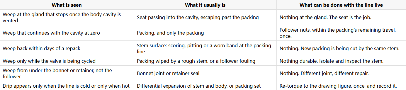
The part nobody inspects: the stem itself
The packing seals against the stem, which makes the stem the only component in the valve that is both a pressure boundary and a sliding surface. It is also the only one that cannot be renewed in place. Everything that goes wrong with a stem shows up first as a leak at the packing line: a band of pitting where the packing sits and the air does not reach, a scratch from grit dragged through the gland during a repair, a taper from a stem that has been bent by a side-loaded lever, or a worn ring where the packing has been working for years.
This is why some stem leaks cannot be fixed today, and why it is worth saying so plainly rather than tightening the gland a fifth time. A new packing set on a pitted stem will seal for a shift and then weep again, because the pits are deeper than the packing can flow into and the edges of the pits cut the rings as the stem turns. The repair is a new stem, and a new stem needs the valve open. That is a shutdown, planned, with the parts in store — not a gland job.
What belongs on the drawing, in the manual and in the store
Five things repay the effort. First, state on the drawing whether a backseat exists, and whether it is a sealing backseat or a retention shoulder, because that single line decides whether a live repack is even on the table. Second, give the gland a torque figure and name the packing, because "tighten as required" is how packings get crushed and how a site loses the ability to tell a worn packing from an over-compressed one. Third, put the packing set, the follower studs and nuts, and one stem into the recommended spares, in that order of likelihood — the stem is rarely stocked and it is the part that turns a one-day job into a two-week one. Fourth, record the as-found torque at every repack, since a rising trend is the only early warning that the stem is no longer round or no longer smooth. Fifth, write the isolation requirement: which side to depressurise, whether the cavity has to be vented, and what reading proves it, so that the decision is made by procedure rather than by whoever is on shift.
None of those five is a specification of the valve. They are the difference between a valve that can be maintained and a valve that can only be replaced, and they cost a paragraph each.
J-VALVES builds floating and trunnion ball valves from 1/2 to 56 inch (DN15 to DN1400) in ASME Class 150 to 2500, with shell tests at 1.5 times and seat tests at 1.1 times rated pressure to API 598, wetted parts certified to EN 10204 3.1, and a drawing set that shows the gland arrangement, the packing type and whether the stem has a sealing backseat or a retention shoulder. Where a customer needs the stem to be serviceable without breaking the line, double packing with a lantern port is quoted as an option at the enquiry stage rather than offered as an afterthought, because it changes the bonnet before it changes anything else.
Frequently Asked Questions
Can a ball valve be repacked under pressure? Only if it was built with a genuine backseat or with double packing and a lantern port, and only if the drawing says so. Most ball valves have neither: the stem turns a quarter turn without axial travel, so there is no shoulder that can land on a seat, and the packing is the only barrier. On those valves the line has to be isolated and the cavity vented before the gland is opened.
Why does tightening the gland stop working? Because packing is compressed, not infinitely compressible. Past a certain point the rings are being crushed rather than loaded, the contact stress on the stem stops rising and stem friction keeps climbing. The follower also reaches the shoulder of the stuffing box and can travel no further, at which point the nuts turn without changing anything. Beyond that the packing extrudes into the stem clearance and is sheared.
How do I tell a stem leak from a seat leak? Close the valve and vent the body cavity to zero. A leak that continues at the gland with the cavity at atmospheric is coming along the stem from the line side. A leak that stops when the cavity is vented was passing the seat and using the gland as an exit. A seat test will not tell you this, because the stem is at line pressure throughout the test either way.
Is a dripping gland dangerous? The drip itself is a loss of containment and it gets worse, but the immediate hazard depends on the fluid: a drip of water is housekeeping, a drip of hydrocarbon or ammonia is a release that has to be managed, and a drip on a line above electrical equipment is a different problem again. What is common to all of them is that tightening buys time and does not remove the cause.
Does a leaking gland mean the valve is scrap? No. It means one of four things, and three of them are repairable: a packing set, a follower that has bottomed out, or a bonnet joint that was mistaken for the gland. The fourth is a damaged stem, and that one needs the valve open but still does not condemn the valve.


