


CHINA J-VALVES Offers Various High-quality I ndustrial Ball Valves
J-VALVES, a distinguished professional ball valve manufacturer rooted in China, takes pride in its extensive product portfolio. Our offerings span a wide range, including trunnion-mounted ball valves, floating ball valves, high-temperature ball valves, high-pressure ball valves, metal-sealed ball valves, ultra-low temperature ball valves, DBB ball valves, Three-way And Four-way Ball Valve, and fully welded ball valves. Each product is a testament to our commitment to precision engineering and reliable performance. Meticulously crafted, they are designed to not only meet but exceed the most stringent industrial demands, ensuring stable operation even under extreme conditions. This enables us to provide our clients with high-value services and makes our valves widely sought-after in industries.
Product Category
Contact Us

Pressure Class: ASME Class 150 to 900 / PN20 to PN150
Body Material: Forged A105N, LF2, F316, F51
Body Construction: Fully welded, no body joint
Ball: A105N or F316, hard chrome or ENP plated
Seat: PTFE, RPTFE, PEEK, or metal seated, self-relieving
Stem: Extension 500 mm to 3 m, sealed tube with guide bushes
Packing: Primary at top, secondary at base of extension
Coating: Three-layer PE or fusion bonded epoxy, 1.5 to 3 mm
End Connection: Butt weld to ASME B16.25
Cathodic Protection: Continuous or isolated by insulating joint
Drain and Vent: Body cavity drain, extendable to surface
Design Standard: API 6D, ASME B16.34, ISO 15848-1 on request
Operation: Handwheel or gear at grade, actuator on request
-
DQ367F
-
J-VALVES
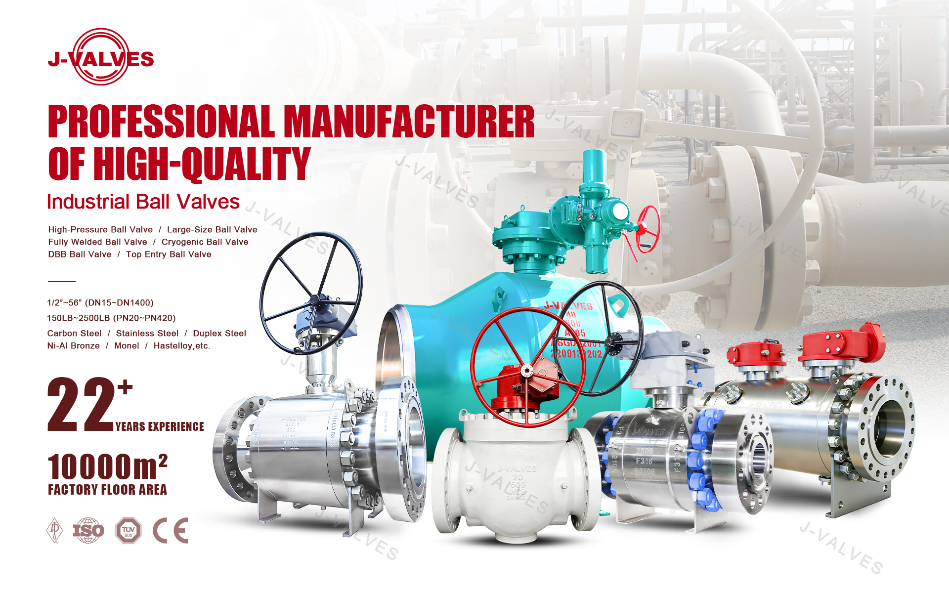
A fully welded buried trunnion ball valve is a pipeline isolation valve with a body that has no bolted joint at all, welded directly into the line and installed below ground, with the stem carried up through a sealed extension tube to an operator at or above grade. Nothing about it is designed to be opened in service: the body is welded shut, the ball and seats are installed before the final weld, and the only moving seal is the stem packing at the top of the extension.
J-VALVES builds this valve from 2 inch to 36 inch in Class 150 to 900, in forged A105N, LF16, F316 and F51, with butt weld ends, three-layer PE or epoxy coating, and stem extensions from 500 mm to 3 m. The buyers are gas distribution and transmission operators, airport fuel systems and water authorities, where the valve is under a road, a runway or a field and the maintenance philosophy is that there will never be maintenance. This page is about the three things that decide whether that philosophy holds: the welded body, the extension tube, and the coating and cathodic protection interface.

Why No Joint Is the Right Answer Underground
A buried valve with a bolted body joint has a cavity around it, whether that is a chamber, a pit or just disturbed backfill. That cavity collects water, the water sits against the joint, and the joint is the one place where the coating cannot be continuous. A flanged or bolted valve underground therefore combines three risks: external corrosion at the joint, a leak path that cannot be seen, and a gas accumulation point under a road or a slab.
A fully welded body removes all three. There is no joint to corrode, no gasket to relax, and the external surface is a continuous coated shape that can be wrapped and holiday tested. The trade is that the valve cannot be repaired: if a seat fails, the valve is cut out. That is accepted because a buried valve in a distribution network is expected to operate rarely, and because the alternative, a chamber with a bolted valve, has its own failure modes and a much higher installed cost.
The same logic explains why the body is welded and not merely flanged and buried. Codes and operator standards in most countries require that a valve below ground with no accessible chamber has no detachable joint in the pressure boundary, and that requirement is met only by a welded body with welded ends.

The Stem Extension Is the Real Product
On a buried valve the extension is not an accessory. It is the part that fails, and it fails in a specific way: water enters the annulus between the stem and the tube, sits at the bottom, and corrodes the stem or freezes and splits the tube. The packing at the top then cannot be reached without excavating, and the valve becomes inoperable while still holding pressure.
A properly built extension has four features.
A sealed tube, not an open pipe. The tube is closed at the bottom where it meets the bonnet and at the top where it meets the operator mounting. Water must not be able to enter at either end.
Two packings, not one. The primary packing sits at the top of the extension, accessible from grade. A secondary seal at the bottom of the extension protects the valve if the primary is adjusted or replaced.
A stem that is guided, not cantilevered. A 2 m extension on a 6 inch valve puts a bending load on the stem if the tube is not guided, and the stem will rub the tube and eventually wear through. Guide bushes at intervals along the tube keep the stem central.
A drain or vent at the low point. If water does get in, it needs somewhere to go. A small drain plug at the base of the extension allows the annulus to be checked and dried during installation, and its presence is a good indicator of whether the design was thought through.
Extension length | Typical use | Design points |
|---|---|---|
500 to 800 mm | Valve under a footpath or shallow cover, operator in a small surface box | Single guide bush, standard packing, handwheel at grade |
800 to 1500 mm | Under a roadway, operator in a road box | Two guide bushes, extension support collar, box drain |
1500 to 3000 mm | Deep burial, airport runway, river crossing approach | Guided at intervals, gear operator at top, torque loss through the extension checked |
The torque loss through a long extension is worth calculating rather than assuming. Every guide bush adds friction, and a stem that is slightly out of line adds more. A valve that needs 400 Nm at the ball may need 550 Nm at the handwheel after a 2 m extension with three bushes, and a gear ratio chosen on the valve torque alone will leave the operator unable to turn it. The figure should be measured on the assembled valve, not calculated from a catalogue.
Coating, Field Joints and Holiday Testing
The external surface of a buried valve is the part that decides its life. Three-layer polyethylene is the default for transmission lines: an epoxy primer, a copolymer adhesive and a polyethylene topcoat, applied at about 1.5 to 3 mm total thickness. Fusion bonded epoxy is used where the operating temperature is higher or where the coating will be handled roughly. Both are applied to a blasted surface and both are inspected for holidays, which are pinholes or thin spots that become corrosion initiation sites.
The field joint is the weak point, as it is on every coated pipeline. The valve ends are welded to the pipe, the weld burns back the coating, and the joint has to be coated in the field with a shrink sleeve, a tape wrap or a flame sprayed system. A field joint coating that is not compatible with the plant coating, or that is applied to a wet surface, will fail within a few years and the failure will be invisible. This is why the specification should name the field joint system and require it to be inspected, not leave it to the contractor.

Cathodic Protection and Where the Insulation Goes
A coated buried valve is connected to the pipeline and therefore to the pipeline cathodic protection system. The coating is the primary barrier and the CP is the backup for the holidays that always exist. The two work together only if the electrical continuity is intentional and the current path is understood.
There are two arrangements. In the first, the valve is electrically continuous with the pipe, receives CP current from the same system, and needs no isolation. In the second, the valve is isolated from the pipe at one or both ends by an insulating joint or an insulating flange, so that the CP system of one side is not drained by the other, or so that the valve can be electrically surveyed independently. On a buried valve the second arrangement is common at station boundaries and at pipeline ownership changes.
The practical point is that the coating, the CP and the insulation have to be designed together. A valve that is fully coated and then bonded to the pipe with a bare weld and no coating at the field joint becomes a coated structure with one large holiday, and the CP current concentrates there. A valve isolated at one end and not the other is a valve with an unintended current path. Neither failure is visible from the surface, and both are found years later by a survey.

Drain, Vent and Double Block and Bleed Underground
A buried valve is normally fitted with a body cavity drain and, where double block and bleed is specified, with the bleed extended to the surface alongside the stem extension. Both are small bore connections that have to be coated, sealed and terminated in a surface box, and both are a common source of leaks because they are installed last and inspected least.
The cavity relief question is the same as on any large ball valve, with one addition: a buried valve cannot be watched. A self-relieving seat is standard, and the drain allows the cavity to be vented and checked at commissioning. If the drain is not extended to the surface, the valve cannot be checked at all after installation, which is a design decision worth questioning.
What to Put on the Enquiry
Size, class, body material, full or reduced bore, design temperature, fluid, whether the line is pigged, weld end preparation, extension length from body centre to operator mounting face, whether a gear or handwheel is required at the top, coating system and thickness, field joint system, cathodic protection arrangement and whether insulating joints are needed, drain and vent requirements and whether they extend to the surface, and the documentation and testing requirements. The extension length and the coating system are the two items that most often arrive late and hold up fabrication.
Frequently Asked Questions
Why is a buried ball valve fully welded instead of flanged?
Because a bolted joint underground is a corrosion site, an invisible leak path and a gas accumulation point in a pit or chamber. A fully welded body removes the joint, leaves a continuous coated surface that can be holiday tested, and meets the requirement in most operator standards that a valve with no accessible chamber has no detachable joint in the pressure boundary.
How long can the stem extension be?
From 500 mm for shallow cover to 3 m or more for deep burial, and the limit is set by torque loss and stem guidance rather than by a catalogue maximum. Beyond about 1.5 m the stem needs guide bushes at intervals, and the operating torque at the top should be measured on the assembled valve rather than calculated from the valve torque alone.
What is the most common failure of a buried valve?
Water entering the stem extension tube and corroding or freezing around the stem, not a seat failure. A properly built extension is sealed at both ends, has two packings, guides the stem and has a drain at the low point so the annulus can be checked. The second most common failure is the field joint coating on the weld ends.
Does a buried valve need cathodic protection?
It is normally connected to the pipeline CP system, with the coating as the primary barrier and the CP as backup for holidays. Whether the valve is electrically continuous with the pipe or isolated by an insulating joint at one or both ends is a design decision, and the coating, the CP and the insulation have to be designed together rather than separately.
Can a fully welded valve be repaired?
No. The body cannot be opened, so a failed seat means the valve is cut out and replaced. That is accepted for buried distribution valves that operate rarely, and it is why the seat material and the ball finish are specified conservatively at the order stage: there is no second chance after installation.
Hot Products


News
Ball Valves in Geothermal Brine: Silica Scale, Chloride Cracking And The Cooling Trap
Why geothermal brine destroys ball valves: retrograde silica scale, calcite at the flash point, chloride cracking above 60 C and the 250 C seat limit.
Read More
Ball Valve Face To Face Dimensions: Why A Correctly Ordered Replacement Still Does Not Fit
A 6 inch Class 150 ball valve can be 267 or 305 mm face to face and both are compliant. How B16.10, EN 558 and flange drilling decide whether it fits.
Read More
Ball Valve Stem Key And Keyway: What Gives Way First, And What The Handle Cannot Tell You
Between the handle and the ball there are four fits. Which one shears, which one cracks, and how a few degrees of lost motion hides a valve that never seated.
Read More
Ball Valve Datasheet: Six Blocks That Decide Whether Two Quotes Are Comparable
A ball valve datasheet only works when six blocks are fixed: pressure basis, bore, temperature ceiling, test, end connection, operator. How each is written.
Read More