


The proof test was scheduled for two in the afternoon and the valve did not close. It was a ten inch Class 600 trunnion ball valve on a tank farm outlet, metal seated, with a spring return pneumatic actuator and a two position three way solenoid. The instrument air was isolated, the solenoid was de-energised, and the actuator was heard to exhaust. The valve travelled from open to about 84 degrees and stopped. The limit switch, set at 85 degrees with two degrees of tolerance, made, and the control system logged the valve as closed.
Nothing in the documents was wrong, and that is the part worth dwelling on. The actuator had been sized against the valve manufacturer's break torque with a factor of 1.5, and the air stroke torque comfortably exceeded it. The spring data sheet quoted the spring torque at the air end of the stroke, which is the highest value the spring ever produces, and that number exceeded the break torque too. What nobody compared was the spring torque at the end of the fail stroke, where the spring is nearly extended and its force is lowest, against the seating torque, which is the highest torque the valve ever demands and is demanded at exactly that position. The spring could get the valve moving and could not finish the job, and a ball valve that is six degrees off its seat is not nearly closed. On a ten inch bore with a 0.5 bar differential, six degrees of ball rotation is an orifice of several square centimetres.
Fail-safe is not a feature that appears as a checkbox on a datasheet. It is a claim about two curves that have to be compared point by point, and it is a claim about a stored energy source that has to still be there after five years of coastal air, three shutdowns, a paint job and a maintenance contractor who closed the air isolation valve and did not tag it. This article sets out the four questions that decide the hardware, works the arithmetic for both spring return and stored air, and lists the failures that happen without any alarm.
1. Four questions before any hardware
The first question is the target position: closed, open, or unchanged. The second is the event: loss of instrument air, loss of electrical power, loss of the control signal, loss of hydraulic pressure, or fire. These are different events with different consequences and a single valve can only be optimised for one of them. The third is how fast, which is a process question about surge, mixing and inventory rather than a question about actuators. The fourth, which is usually left out of the datasheet and is the one that decides whether any of the first three can be relied on, is how the plant will know if the failure mechanism has already failed.
A useful discipline is to write the sentence out in full before selecting anything: on loss of instrument air the valve shall move to closed within four seconds and remain closed with no air supply, and the closed position shall be proved by a switch that detects stem position rather than actuator travel. That sentence contains five separate requirements, and each one eliminates hardware.
2. Loss of air is not loss of power is not loss of signal
Most of the confusion in fail-safe discussions comes from treating three independent utilities as one. A spring return actuator responds to loss of air, and it does so regardless of what the electrical system is doing, because the spring is not connected to the electrical system. A double acting actuator with an accumulator responds to loss of air only if the accumulator is on the actuator side of a check valve, which is a piping detail and is sometimes drawn wrongly. An electric actuator responds to loss of power, and to nothing else unless it has a stored energy pack of its own.
The electrical side has its own trap, which is the solenoid wiring convention. A spring return actuator usually carries a three way solenoid that is energised to hold the valve in its normal position and de-energises to trip. Whether "energised" means open or closed is a decision made at the wiring stage, and it has to match the cause and effect matrix, not the vendor's default. Two identical valves on the same unit, one energise to open and one energise to close, look the same on a P and ID and behave in opposite ways when the panel loses power. This is discovered during commissioning, or during the first real trip.
The third distinction is the one that catches operating teams. Loss of the control signal on a modulating valve leaves the positioner wondering, and the usual default is to hold the last position, which is neither open nor closed. On an on-off valve with a solenoid the signal and the power are usually the same circuit, so signal loss and power loss coincide. On a valve with a positioner and a separate trip solenoid they do not, and the valve will hold position on signal loss and only trip on the solenoid. If the safety case assumed the first behaviour, the second is a gap.
3. Torque is a curve, not a number
A ball valve demands torque at four distinct moments, and they are not equal. Breaking the valve off its seat, whether opening or closing, is the highest demand in most designs because the seat has been loaded against the ball for a long period and the polymer has taken a set. Running torque, once the ball is moving, is typically 40 to 60 percent of break torque because only the seat friction and the stem bearing remain. Seating torque at the end of travel is the second highest and can equal or exceed break torque, particularly on a metal seated valve where the final few degrees load a wedge or a spring behind the seat. And every one of those numbers rises with age, with temperature, and with the amount of solids that have deposited on the ball.
The spring, meanwhile, produces its highest torque when it is most compressed, which is the position the air holds it in at the end of the air stroke, and its lowest torque when it is most extended, which is the end of the fail stroke. So the spring is strongest where the valve needs the least and weakest where the valve needs the most. That inversion is the whole engineering problem of spring return actuation, and it is why a sizing sheet that quotes one spring torque is not a sizing sheet.
Point in travel | Valve demand, cold and clean | Valve demand, aged and at minus 20 C | Spring available at that point | Margin |
|---|---|---|---|---|
Break to close, from full open | 2,600 N m | 3,400 N m | 3,050 N m | 0.90, short |
Running, mid travel | 1,150 N m | 1,500 N m | 2,600 N m | 1.73 |
Seating, final 5 degrees | 3,200 N m | 4,300 N m | 2,150 N m | 0.50, fails |
Break to open, from seated | 3,200 N m | 4,300 N m | 3,050 N m on air stroke, not spring | Depends on air |
The numbers above are for a ten inch Class 600 metal seated valve in dry gas at 40 bar, and the pattern they show is typical rather than extreme. The air stroke torque of the same actuator was 6,800 N m, which is why the valve looked well specified on paper. The spring had roughly 45 percent of the air torque at the air end and 32 percent at the fail end, which is a normal ratio for a single acting scotch yoke actuator and is exactly why a spring return unit cannot simply be substituted for a double acting one of the same size.
Two derating factors have to be applied before the comparison is made, and both are routinely omitted. The first is temperature: an elastomer seat at minus 20 degrees C is stiffer, grease in the stem bearing is thicker, and the valve demand rises by 25 to 60 percent over the ambient figure. The second is condition: a valve that has been in service for a few thousand cycles, with a film of deposited solids on the ball and a seat that has taken a set, demands more than the factory figure, and 30 to 50 percent is a reasonable allowance. A spring sized against the clean cold number is not sized at all.
4. Where the spring runs out, and what to do about it
Spring return actuation has a practical ceiling, and it is set by the volume of air that has to be displaced to compress a spring strong enough for the job. Above roughly 24 to 30 inch bore, or above about 20,000 N m of seating torque, a single acting actuator becomes a large, heavy and expensive object, and the alternatives start to win on total cost rather than only on capability.
Option | Stored energy | Fail direction | Practical torque ceiling | Where it wins |
|---|---|---|---|---|
Spring return, single acting | Compressed spring | One fixed direction | About 20,000 N m | Most on-off shutdown valves up to 24 inch; no air needed to trip |
Double acting with receiver | Compressed air in a bottle | One direction, defined by piping | Very high | Large valves, high torque, where a spring is impractical |
Gas over oil | Gas pressure on hydraulic fluid | One direction, smooth and slow | Very high | Pipeline stations, large bore, controlled closing time |
Electro hydraulic | Hydraulic accumulator | Programmable, often adjustable | Very high | Subsea, remote sites, no instrument air available |
Electric with stored energy pack | Capacitor or battery | One direction, on power loss | High, slow | Modulating duty, no air, closing time measured in tens of seconds |
Fail last, lock valve | None | None; holds position | Any | Sampling, dosing, sections where closure creates a hazard |
It is also worth saying what a spring does not do. A spring return actuator cannot hold an intermediate position, so it is unsuitable for modulating duty without a positioner and a lock up device. A spring cannot be tested without stroking the valve, so its health is only visible at a proof test. And a spring lives inside a cylinder that is vented to atmosphere on one side, which means the spring is exposed to whatever the plant atmosphere contains, and in a coastal or a chemical plant that is a corrosion environment. A spring that has lost 15 percent of its force through corrosion or through a broken coil still moves the valve most of the way, which is the worst possible outcome: it looks like a working safety device.
5. Stored air: the arithmetic, and why receivers get big
The alternative for large valves is a double acting actuator fed from a dedicated air receiver through a non return valve, so that a loss of the plant air header does not empty the receiver. The actuator then has a defined quantity of stored energy and a defined number of strokes available. The arithmetic is isothermal expansion of a fixed mass of air into an increasing volume, and it is worth doing explicitly because the answer is usually larger than expected.
For a receiver of volume V1 at absolute pressure P1, expanding into an actuator whose stroke volume is Vs and ending at the minimum pressure P2 that still produces the required torque, the volume balance gives V1 equal to P2 times Vs divided by the difference between P1 and P2. For a ten inch actuator with a stroke volume of 32 litres, a receiver charged to 8 bar absolute and a minimum usable pressure of 6 bar absolute, that is 96 litres. If the minimum usable pressure is allowed to fall to 5 bar absolute instead, the same duty needs 53 litres. Halving the receiver is a decision about torque margin, not about air, and it has to be justified by showing that the actuator still seats the valve at 5 bar.
Three details turn a calculation into a working system. The non return valve has to be on the receiver outlet with no bypass, and it has to be a type that seals at low differential rather than a soft seated check that weeps. A pressure switch on the receiver is the only way to know the stored energy is there, and it should be alarmed rather than indicated. And the receiver needs a drain, because instrument air carries water and a receiver that is half full of condensate has half the stored energy the calculation assumed while showing full pressure on the gauge.
6. Closing time, and the surge you cause by being fast
The third question, how fast, is where a safety requirement and a mechanical requirement pull in opposite directions. Fast closing is good for inventory isolation and bad for water hammer. The dividing line is the pipe period: twice the length of the line divided by the acoustic velocity of the fluid. If the valve closes in less time than that, the decelerating column cannot relieve itself and the full Joukowsky pressure rise appears at the valve, equal to density times acoustic velocity times the change in velocity.
For a two kilometre water line, the pipe period is about 3.6 seconds, so a valve that closes in one second produces the full surge and one that closes in ten produces almost none. At 4.5 metres per second initial velocity, density 1,000 kilograms per cubic metre and acoustic velocity 1,100 metres per second, the full rise is 49 bar on top of the static head. That is enough to lift a flange on a Class 300 line, and it is produced by a valve doing exactly what the cause and effect matrix asked for.
Where the process needs both a fast trip and a soft landing, the answer is a flow control arrangement on the exhaust rather than a slower trip. A quick exhaust valve gets the actuator moving immediately, and a needle valve or a graduated orifice in the exhaust path controls the last part of the stroke. A cushion at the end of the cylinder does the same job hydraulically. What does not work is specifying a slow closing time and hoping the trip is still fast enough, because the first 80 percent of the travel is what isolates the inventory and the last 20 percent is what breaks the pipe.
7. Fail last, and the cases where it is correct
Fail last, meaning hold the last position on loss of motive power, is achieved either by a lock valve that traps air in both cylinder ports or by a dedicated pilot operated check. It has no stored energy source of its own, so it cannot be tested by removing a utility, and it has no deterministic position, which is why a hazard study usually rejects it for a shutdown function. It is nonetheless the right answer in a specific set of cases: a valve on a sampling or dosing line where closing would create a pressure excursion elsewhere, a valve in a recirculation loop where the process is indifferent to position, and a valve whose closure would strand a large inventory in a section that has no relief.
The distinction that resolves most arguments is whether the valve is protecting the process from the utility or the utility from the process. If a loss of air means the process is now unmanaged and the safe state is isolation, the valve fails closed. If a loss of air means the process is now unmanaged and the safe state is to keep the existing flow path, the valve fails last, and the safety function belongs somewhere else. Writing that down in the cause and effect matrix is more valuable than any amount of actuator selection.
8. The failures that happen without an alarm
The most dangerous property of a fail-safe system is that it is dormant. It does nothing for years, and its failure is invisible until the day it is needed. The following are the ones that recur in investigation reports, in rough order of frequency.
Failure | What the control room sees | How to detect it |
|---|---|---|
Exhaust silencer blocked by paint, ice or insect nest | Nothing; valve appears healthy until a trip | Measure closing time at every proof test; a slow or incomplete stroke is the signature |
Air supply isolation valve closed and not tagged | Nothing, if the actuator is holding position | Pressure switch downstream of the isolation valve, alarmed, not indicated |
Spring corroded or a coil broken | Nothing; the valve still strokes on air | Compare closing time against the commissioning baseline; strip at major overhaul |
Solenoid wired to the wrong normal state | The valve works, in the wrong direction, on power loss | Cause and effect test with the panel, not with the local switch |
Manual override left engaged after maintenance | Nothing; the actuator strokes but the stem does not | Stem position switch rather than actuator travel switch; a physical check at handback |
Seat bonded to the ball by deposits | Nothing until the trip, when the valve stalls off seat | Break torque trend at each stroke; cycle the valve on a schedule |
Receiver half full of condensate | Full pressure on the gauge, half the stored energy | Drain at every inspection; a level or a sight glass on large receivers |
Two of these deserve emphasis because they are cheap to fix and are fixed rarely. The exhaust silencer is the single most common cause of a spring return valve failing to complete its stroke, because it is the smallest orifice in the entire exhaust path and it is exposed to the plant atmosphere. A silencer that has been painted over during a maintenance campaign, or that has iced up on a cold morning, turns a correctly sized actuator into an undersized one. The remedy is either a larger silencer with a known flow coefficient or, better, a protected exhaust routed to a safe location with the restriction designed in rather than accumulated.
The second is the position switch. An actuator travel switch reports where the actuator is, which is not the same as where the valve is, and the difference is the coupling, the key, the stem and the override clutch. A valve that has sheared its coupling, or whose override is still engaged, will show full travel on the actuator and no movement at the ball. A switch that senses the stem, or better a proximity switch on the ball itself for critical duty, costs little and removes an entire failure mode.
9. Proof testing: what a partial stroke does not prove
Partial stroke testing has become the default diagnostic for shutdown valves because it can be done online and it exercises the parts that fail most often: the solenoid, the pilot, the spool and the first part of the actuator stroke. It typically moves the valve 10 to 20 percent and returns it, and it will find a stuck spool, a failed pilot and a seized stem in its first few degrees.
It does not prove that the valve will seat. It does not travel far enough to reach the region where seating torque is demanded, it does not extend the spring to the position where its force is lowest, and it does not test the last 20 percent of the stroke where deposits and seat bonding do their work. Nor does it test the exhaust path at full flow, because the flow through a silencer during a 15 percent stroke is a fraction of the flow during a full trip. A programme that relies entirely on partial stroke testing and never strokes the valve fully is testing the easy half of the system.
The practical arrangement is a full stroke at a defined interval, annual being common, with the closing time measured and recorded against the commissioning baseline, plus partial stroke testing in between for the electrical and pilot path. The closing time is the single most informative number available, because it integrates spring force, exhaust restriction, stem friction and seat condition into one value that can be trended. A valve whose closing time has drifted from 3.2 to 4.8 seconds has told you something that no amount of visual inspection will.
10. Sizing for the cold case
Winter is when fail-safe systems are discovered. Instrument air at minus 20 degrees C carries its water as entrained liquid rather than as vapour, and any low point in the tubing becomes a plug of ice. A solenoid pilot that has water in it will not shift. An exhaust silencer that has collected condensate will block. Nitrile seals in the actuator go from flexible to glassy and the friction in the cylinder rises. None of this is visible on a datasheet written at 20 degrees C.
The three countermeasures are a dew point specification on the instrument air that is actually achieved rather than merely written, a tubing layout with no low points and with drain legs at the low points that exist, and a cold start test at the minimum design temperature with the actual air supply. The last of these is worth the cost of a chamber or of a winter night, because it converts a paper claim into a measured closing time.
11. What goes on the datasheet
A fail-safe actuator datasheet should carry nine numbers and one sentence, and the sentence is the most important. The numbers are the target position, the failure events it must respond to, the maximum closing time, the minimum and maximum supply pressure, the minimum and maximum ambient temperature, the maximum valve torque demand including the ageing and temperature allowance, the minimum torque the actuator delivers in the fail direction at the end of its stroke, the stored volume and its minimum usable pressure where a receiver is used, and the leak rate class of the seat that the whole assembly is expected to achieve.
The sentence is the cause and effect statement, written in the language of the plant rather than the language of the vendor, naming the event, the position, the time and the proof. An actuator selected without that sentence is a mechanical component. An actuator selected from it is a safety function, and the difference shows up on the day the air goes away.
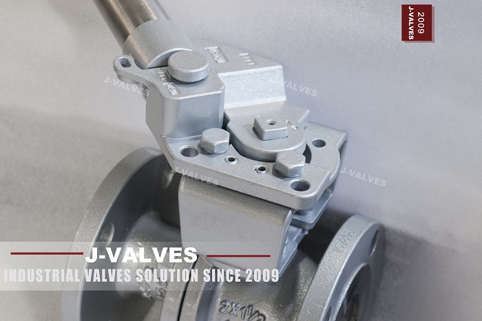
For its part J-VALVES supplies the valve and the mounting interface that the actuator has to be sized against, which is where most of these problems begin: an ISO 5211 pad, a stem with a defined square or keyway, and a published torque curve at the specified pressure, temperature and seat material. Bodies run from 1/2 inch to 56 inch, DN15 to DN1400, in classes 150 to 2500 for temperatures down to minus 196 and up to plus 650 degrees Celsius, and the torque figures issued with each valve are measured rather than calculated, at the temperature the order specifies. Shell and seat proof records are separate documents, and a request for a torque curve at a stated differential, with the seat material named, is answered within three working hours.
12. The one line to remember
A spring return actuator is not fail-safe because it has a spring. It is fail-safe when the spring's weakest point, which is the end of its stroke, still exceeds the valve's strongest demand, which is seating, with the valve aged, cold and dirty. Everything else in this article, from receiver volumes to exhaust silencers, is detail around that single comparison, and that comparison is made once, on paper, before the order, or never.
13. Frequently Asked Questions
Can a spring return actuator be sized on the double acting torque figure?
No, and this is the most common sizing error in the industry. A single acting scotch yoke actuator delivers roughly 40 to 60 percent of its air stroke torque at the air end of the stroke and 25 to 35 percent at the fail end, because the spring force falls as it extends. The spring is strongest where the valve needs least and weakest where the valve needs most, since seating torque is demanded at the very end of the fail stroke. The sizing comparison has to be made point by point against a torque curve, not against a single number.
How large an air receiver does a double acting actuator need?
Size it as V1 equal to P2 times the stroke volume divided by the difference between the charge pressure P1 and the minimum usable pressure P2, all in absolute units. For a 32 litre stroke volume charged to 8 bar absolute and needing 6 bar absolute at the end, that is 96 litres; if the actuator will still seat the valve at 5 bar absolute, the same duty needs 53 litres. The receiver then needs a non return valve with no bypass, an alarmed pressure switch, and a drain, because condensate halves the stored energy while the gauge still reads full.
Does partial stroke testing prove the valve will close on demand?
It proves the electrical and pilot path works and that the first part of the stroke is free, which is where a large share of failures occur. It does not reach the region where seating torque is demanded, does not extend the spring to its weakest point, and does not test the exhaust path at full flow. A programme that uses only partial stroke testing is testing the easy half. Pair it with a full stroke at a defined interval and record the closing time against the commissioning baseline, because closing time integrates spring force, exhaust restriction and seat condition into one trendable number.
Fail closed or fail last for an emergency shutdown valve?
Fail closed, in almost every case, because a shutdown function needs a deterministic position and fail last has none. Fail last is defensible where closing the valve would itself create a hazard, such as stranding a large inventory in a section with no relief, or where the process is genuinely indifferent to position. The test is whether the valve is protecting the process from the utility or the utility from the process, and the answer belongs in the cause and effect matrix rather than in the actuator datasheet.
Why did the shutdown valve not close when the air failed?
In investigation reports the order of likelihood is a blocked exhaust silencer, a closed and untagged air isolation valve, a corroded or broken spring, an actuator sized on air torque rather than spring torque, and a manual override left engaged. All five are invisible until the valve is asked to move. Measure the closing time at every proof test, fit an alarmed pressure switch downstream of the isolation valve, and prove position with a stem or ball mounted switch rather than an actuator travel switch.


