


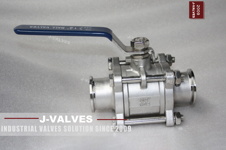
A quarter turn is an instruction, not a measurement
A lever on a ball valve is the most trusted piece of information on a process unit, and it is trusted far beyond what it can actually show. The lever is bolted to a stem, the stem is keyed or flatted to a ball, and the whole assembly is designed to move through one quarter turn between two hard stops. What the lever reports is that the stem has reached a stop. What the operator reads into it is that the ball port is aligned with the bore, the seats are loaded, the line is isolated, and the valve is safe to work on. Only the first of those is what the hardware actually says.
This matters because a ball valve gives no intermediate feedback. A gate valve with a rising stem shows travel; a globe valve with a positioner shows lift; a butterfly valve can be watched through its disc. A ball valve at mid-travel looks like a valve that is somewhere between two states, and a ball valve at either stop looks identical whether or not the ball inside is where the stem says it is. Every position argument on a ball valve therefore rests on one hidden assumption — that the ball is still attached to the stem in the orientation it was assembled in — and that assumption is exactly what fails after a stem has been replaced and re-fitted a spline off, or after a coupling on an extended stem has slipped.
Three states that look like two
Open and closed are the states the operator believes in. The third state, mid-travel, is where most of the damage happens and it is the one with no indicator at all. In a soft-seated valve the seat is loaded by the ball only when the ball is at a stop; at mid-travel the port is half facing the bore, the flow is accelerated through a crescent-shaped gap, and the seat is being wiped across the edge of the port at the highest velocity it will ever see. Slurry, catalyst fines and polymer service destroy seats in this position far faster than in any other, and the valve is usually recorded in the log as open or closed because nobody writes "half open" in a shift handover.
The same position is a hazard for a different reason in a line that must be isolated. A valve cracked open to relieve a trapped volume, then left, then locked off in the belief that it is closed, is a live line with a lock on it. The lock does not know the difference, and neither does the tag. This is why the discipline around ball valves has to rest on evidence taken from the process, not on evidence taken from the operator.
Where the position actually lives
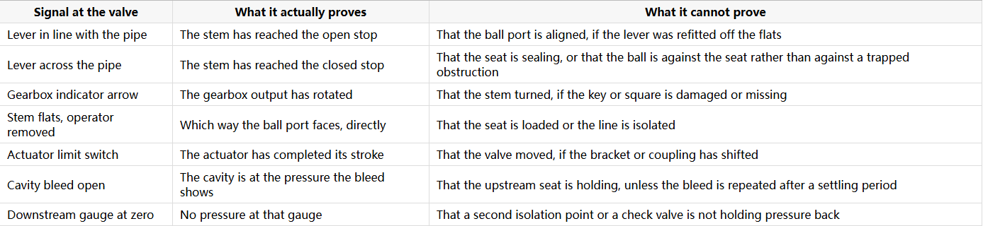
Four places on a ball valve can carry position information, and they are not equally trustworthy. The lever is the primary indication: in line with the pipe means the port is aligned with the bore, across the pipe means it is not. That convention is reliable only if the lever was fitted to the stem flats correctly, which is an assembly check, and it is the first thing to verify on a valve that has been rebuilt.
The gearbox indicator is a small plate or arrow on top of the gear operator that turns with the input shaft. It is a mechanical indication of the gearbox, not of the valve: it shows what the gearbox output has done, and the gearbox is connected to the stem by a key or a square. If the key is missing, the arrow still moves. Gear operators also have a limit of travel set by stop screws, and those stops can be adjusted in the field by anyone with an Allen key, which means the arrow can be made to read CLOSED while the ball is still a few degrees off the seat.
The stem flats are the most honest indication on a bare valve, and the least used. The flats on a ball valve stem are machined parallel to the ball port, so with the operator removed the flats show which way the port faces. This is the check to make before fitting an actuator or a new lever, and it is the check that catches a ball assembled a quarter turn out.
The actuator adds limit switches, a visual position indicator on the housing, and often a local declutch lever. All of these report the actuator's own travel, and the actuator is mounted on a bracket to a pad. A bracket that has shifted, a coupling that has worn, or a stem adapter fitted a spline off produces a full set of confident signals from an actuator that is driving nothing.
What a lock is actually locking
A lockable ball valve is one of the few places where a padlock is expected to stop a process, so it is worth being precise about what it blocks. On a lever-operated valve the hasp passes through a hole in the lever or through a bracket that traps the lever, and it prevents the lever from being moved. On a gear-operated valve the lock goes through the handwheel or through a device that blocks the input shaft. On an actuated valve the lock is normally on a manual override, a supply isolator or a declutch, not on the valve itself.
Each of those locks blocks a mechanical input. None of them blocks stored energy, and stored energy is what actually moves a ball valve. A pneumatic actuator with a spring return holds energy in the spring whenever the valve is in its normal position; blocking the air supply does not remove that energy, and releasing the manual override on a spring-return unit will stroke the valve whether or not a padlock is on the handwheel. A gas-over-oil actuator holds energy in a gas bottle and an oil reservoir, and closing a ball valve on the gas supply leaves both. Even a manual valve can be moved by thermal expansion in a liquid-filled body, which is why a locked-off valve with no cavity relief can lift a seat rather than stay put.
The practical rule is that the lock goes on the energy, not only on the operator. For a spring-return actuator that means locking out the air supply and then proving the spring has been discharged, or mechanically restraining the stem, depending on what the unit provides. For gas-over-oil it means isolating the gas bottle and bleeding the oil circuit. For a manual valve on a line that can be pressurised from either side it means locking the valve and separately locking or blanking the other isolation point, because the valve lock does nothing about pressure arriving from downstream.
Tagging is the second half. A lock without a tag tells the next shift that something is protected but not what, by whom, or against what. A tag without a lock tells them the opposite. The pair is the unit of control, and on a ball valve the tag should name the valve, the line, the energy sources isolated and the person who holds the key.
The stored-energy case that catches people: spring return and ESD
Spring-return actuators are specified precisely because they fail in a defined direction, and that same property makes them dangerous to lock out casually. The spring is compressed in the normal position and released on air failure, so the valve has a stored source of motion that is independent of the instrument air header. Locking the air supply closed is necessary and not sufficient: the spring still holds energy, and any action that vents the cylinder — a maintenance bypass, a test of the solenoid, a filter regulator drained by someone else — will stroke the valve.
The reverse case is just as common. A double-acting actuator has no spring, so its stored energy is the trapped air in the cylinder, and that air can hold the valve in position for a long time after the header is isolated. A valve that has been locked and tagged and looks stationary can still move when a tube is cracked. The spring-return and double-acting ESD article covers how the two arrangements behave on air failure; for lockout purposes the difference is that one stores energy in a spring and the other stores it in a volume of compressed air, and both have to be discharged and proved before work starts.
Buried valves: the indication is above ground, the seat is not
An extended stem moves the operator to the surface and leaves the valve in the trench, and that arrangement breaks the chain of evidence at the coupling. The lever at the surface indicates that the top of the extension has turned. Between the top of the extension and the ball there is a joint — a keyed sleeve, a pinned coupling, a square drive — and that joint is the part that can slip, corrode or be assembled a spline off. A buried valve whose extension coupling has failed shows a full quarter turn at the surface and no movement at the ball.
This is why buried installations need a position check that does not depend on the surface operator alone: a cavity bleed brought to the surface, a downstream pressure gauge at the surface, or a proving procedure that closes the valve and confirms the effect on the process before the lock is applied. The buried valve and extended stem article sets out which functions have to be brought to the surface with the stem, and the position check belongs on that list rather than being treated as an operating detail.
Sealing is not the same as isolating
A ball valve that passes its seat test holds pressure in the direction it was tested. That is a statement about leakage, not about isolation. Isolation requires that no flow path exists, and a ball valve has several: past the upstream seat, past the downstream seat if it is double piston effect, through the cavity bleed if it is left open, through the stem seal, and around the valve entirely if a bypass exists. A lock on the lever addresses none of these.
The only evidence that a ball valve is isolating is a pressure reading that stays at zero after the valve is closed and after the volume downstream has had time to equalise. That is what a bleed is for, and it is why double block and bleed exists as an arrangement rather than as a feature. The DBB isolation article explains what the bleed proves and, more usefully, what it does not: a bleed that stays dry proves the upstream seat is holding at that moment, not that it will hold for the duration of the work, and it says nothing about the downstream side.
Throttling with a ball valve, and the position nobody records
The most common position-indication failure in practice is not a broken indicator. It is a valve deliberately left part open and never recorded, because a standard ball valve looks like it can throttle and the lever position suggests a setting. A standard port ball at mid-travel produces a flow characteristic that is nearly impossible to control — most of the travel does almost nothing and the last few degrees do everything — and the seat sees the erosion that goes with it. If a line genuinely needs a throttling position, the valve should be a characterised one and the position should be an instrument reading, not a lever angle. The V-port throttling article covers where that boundary sits.
What to write into the specification
Position and lockout requirements are usually lost because they are written as adjectives. Six lines fix them. State that the valve must be lockable in both the open and the closed position, and name the device that does it, because a lockable lever and a lockable gearbox are different hardware. Require a position indicator that is directly coupled to the stem rather than to the gearbox input, and require the stem flats to be machined parallel to the ball port with the orientation checked at assembly. For actuated valves, state which energy sources must be isolatable and lockable, and whether the actuator can be declutched with the spring compressed. For buried valves, list the functions that must be brought to the surface, including the position check and the cavity bleed. Finally, require the operating and maintenance manual to state the proving procedure for isolation, so that the site has a written sequence rather than a habit.
J-VALVES supplies ball valves from 1/2 to 56 inch (DN15 to DN1400) in ASME Class 150 to 2500 with lever, gear, pneumatic and electric operation, shell tests at 1.5 times and seat tests at 1.1 times rated pressure, and ISO 5211 mounting pads for actuator fitting. Locking devices, indicator type and the stem-to-ball orientation check are specified per order rather than assumed from the size, because two valves of the same size can differ in exactly the details that decide whether the lever means anything. Maintenance access is the other half of the same decision, and the top entry versus side entry comparison explains why the body style changes what a maintenance lock has to protect.
Frequently Asked Questions
Does a lever position prove a ball valve is closed? It proves the stem has reached the closed stop. It does not prove the ball is oriented as the stem suggests, that the seat is sealing, or that the line is isolated. The checks that go beyond the lever are the stem flats with the operator removed, the cavity bleed, and a downstream pressure reading that stays at zero.
Can a ball valve be locked in the open position as well as closed? Yes, and for isolation work it should be. Many lockout procedures only address the closed position, which leaves a valve that must stay open for a running system unprotected. A lockable lever with a hole at both ends of travel, or a gearbox with a lockable handwheel, covers both, and the specification should say which of the two is required rather than leaving it to the supplier.
What is the difference between locking a valve and isolating it? A lock prevents a mechanical input from moving the operator. Isolation means no flow path exists and the absence of pressure has been demonstrated. A locked valve can still be pressurised from the other side, can still be moved by a spring-return actuator, and can still pass through a damaged seat. Locking is one step in an isolation procedure, not a substitute for one.
Why does a gearbox indicator sometimes disagree with the valve? Because the indicator is driven by the gearbox input or output shaft, not by the ball. A missing or worn key, a stem adapter fitted off the flats, or stop screws adjusted in the field will all let the arrow point at CLOSED while the ball is somewhere else. Checking the stem flats directly, with the operator off, is the only way to confirm the ball orientation.


