


A ball valve is a structure before it is a seal
Ask what a ball valve does and the answer is a seal: a ball, two seats, a quarter turn. Ask how it is built and the answer is different. It is a stack of parts held together by force that was applied once, at assembly, and has been sitting there ever since. End pieces or a body and a bonnet, a ball between them, a stem through the top, a seat in each pocket, packing in a gland, bolts around the joint.
Three of those interfaces have no fastener that carries the sealing load. Nothing bolts the ball to its seats. Nothing bolts the stem into its packing. The seat ring is located by its pocket rather than clamped by a bolt, and what holds it against the ball is preload: the seat is squeezed against the ball, the gland squeezes the packing against the stem, and the seat ring is pressed into a pocket and then loaded further by whatever pressure reaches its back face. Take the preload away and the joint does not fail. It becomes a joint that is free to move.
That is the difference this article is about. A ball valve is designed for load, and every part in it is sized for load. It is not designed for displacement, and most of the displacement it sees in service is not generated inside the valve at all. It arrives through the pipe and through the bracket, and it is small enough that no inspection procedure looks for it.
Why a slip is worse than a force
A static load is easy to design against: you know the number, you size the part, you add a margin. An oscillating displacement is a different problem. Two surfaces are held in contact by preload and are then made to slide against each other by an amount far too small to see. The oxide film on a steel surface is thinner than the roughness of that surface. The first slip removes it. The bare metal underneath oxidizes within minutes, and the oxide is harder and more abrasive than the metal it came from.
Now the contact is holding grit that it made itself. The debris cannot leave, because the load is holding the joint shut and the only path out is narrower than the particle. So the next slip grinds that debris across the same two surfaces, and the slip after that grinds it again. The process feeds itself, and it does not need the valve to be operated even once.
Engineers have a name for the result: fretting wear. It has three properties that make it hard to diagnose from the outside. It needs no cycle, so a maintenance system that counts valve operations will record nothing. It leaves a mark that looks like polishing rather than damage, because the debris has been ground to powder. And its only direct evidence is that powder, which sits inside the joint that produced it, behind the very part that has to be removed to see it.
Where the movement comes from
Ball valve vibration has four sources, and only one of them is the valve's own doing.
The first is pump pulsation from the machine upstream. A pump or a compressor that displaces fluid in pulses delivers pressure in pulses. A piston, a plunger or a diaphragm pushes a finite volume, the discharge line absorbs it and the pressure falls back before the next stroke, and the result is a pressure ripple at running speed and at its harmonics. That ripple travels through the liquid as a wave and loads every closed surface it reaches, including the two seats of a closed valve. A centrifugal machine produces a smaller ripple at blade-passing frequency, which is a different frequency but the same kind of load.
The second is turbulence at a partial opening. A valve that is throttled, or one that is a few degrees short of fully open, presents a partly blocked bore. The jet that forms at the edge is high velocity and unsteady, and its energy is spread across a wide band of frequencies. Broadband excitation is worse than a single tone for a structure, because it will find whatever resonance the structure has.
The third is cavitation downstream of the valve. Bubbles that collapse against a surface deliver a series of concentrated impacts at high frequency. If the surface is the cavity wall, the seat carrier or the downstream port, the valve is being hammered at a frequency nobody measures and a force nobody can see.
The fourth is the valve's own geometry. An open ball valve leaves an annular volume around the flanks of the ball, connected to the bore at both ends through the port. That is a cavity with two openings, which is a resonator, and flow across the port can drive it. The same cavity is where the seats live.
The actuator on the pad is a cantilever
The ISO 5211 mounting pad is a flat face, a square drive and four holes. What hangs on it is a mass: the actuator, its solenoid and switch box, the tubing, sometimes a handwheel and a chain. Between that mass and the valve there is a bracket, and between the bracket and the ball there is a stem.
That is a cantilever, and a cantilever has a natural frequency that falls as the mass rises and as the bracket gets softer. A small valve with a large actuator on a fabricated bracket is the worst arrangement available: the bracket's own resonance can sit close to the running speed of the machine it is bolted to, and the amplitude at the stem is then far larger than the vibration of the pipe that started it. Nothing about this is visible. The actuator does not fall off, the bracket does not crack, and the valve still turns.
What it does instead is load the stem sideways. A valve stem is designed for torsion, because its job is to transmit torque from the operator to the ball. It is not designed for bending, and it is supported over most of its length by a packing that was never intended to be a bearing. A stem that is pushed sideways compresses the packing on one side and opens a gap on the other, and the gap is a leak path.
What a side load does to a gland
Stem packing seals because it is compressed in one direction and expands in the other. The gland squeezes the rings axially; the rings expand radially against the stem and against the stuffing box; and the seal is that radial contact. It is a balanced arrangement as long as the stem stays in the middle of the box.
A stem that is pushed to one side is no longer in the middle. The packing is compressed harder on the loaded side and relieved on the opposite side, and the relieved side is where the leak appears. This is why a stem packing leak is so often reported as coming from the side away from the actuator, or from the side a fitter would call the back: the load is on one side and the gap is on the other.
Tightening the gland does not solve it, and it makes the next stage worse. More gland load closes the gap for a while and raises the friction on a stem that is already being bent, so the side load goes up and the gap reopens. What the strip-down shows is a stem with a polished ring at the packing line and packing rings with a flat worn on one side, which is the shape of the load and not the shape of the seal.
The ball and its seats: what actually moves
In a floating ball valve the ball is not fixed to anything. It rests between the two seats and is driven by the stem, and it is the seats that decide where it sits. When line pressure rises, the ball travels downstream until the seat stops it; when the pressure falls, the elasticity of the seat pushes it back. Seat load is therefore a function of pressure, and a pressure that oscillates makes the ball oscillate with it, by whatever distance the seat's compliance allows.
Every one of those oscillations is a small relative displacement at the contact band, and the contact band is the only place in the valve where the seal exists. The band is narrow by design, the load on it is high, and the debris produced there has nowhere to go. This is why a floating valve on the discharge of a reciprocating machine can show ball valve seat wear that matches neither the number of operations nor the cleanliness of the line.
A trunnion mounted ball valve is the obvious answer, and it is half an answer. The ball is carried on bearings, so its position is fixed and the ball does not travel with the pressure. But the seats are still pistons. A spring-loaded seat moves in its pocket whenever the pressure behind it changes, and the seal between the seat ring and the pocket bore, whether that is an elastomer ring or a lip seal, slides with it. The fretting then happens on the pocket bore rather than on the ball.
So the trunnion valve wears its pocket and its seat's secondary seal, and the floating valve wears its seat face and its ball. Same vibration, different victim, and the inspection is in a different place. Seat preload is what both of them depend on, and preload is exactly what an oscillating load keeps interrupting.
What the damage looks like
There are three finishes, and they follow the material pair rather than the valve type.
Steel running on steel, which covers the seat carrier against the pocket, the stem against its bushing, and any bolted joint: a matt patch, sometimes rust-coloured, with red-brown or black oxide powder in it. The patch has sharp edges that follow the contact area, because the contact area is what was moving. It is not a scratch and it does not follow the direction of flow.
Polymer running on steel, which covers PTFE, RPTFE and PEEK seats against the ball: a band that looks burnished rather than damaged, plus a white or grey paste of polymer debris. The band is wider than the original contact and it has lost the fine directional marks left by machining, because the fretting has taken them off. A seat that looks polished all the way across is not a seat that has been working well; it is a seat that has been moving.
Elastomer running on steel, which covers every secondary seal in the valve: a sticky dark residue, a seal that has taken a square section instead of a round one, and a polished ring on the surface it ran against. The section change is the part that matters. A seal that has lost its roundness has lost the interference that made it a seal.
Two placement rules follow, and they are what make the diagnosis possible. The damage is under the seal, not in the flow path, so it cannot be seen through the bore with a light. And it is on the surface that barely moves, so it is never where the wear from normal cycling would be. If the mark is where the flow goes, it belongs to erosion or to debris. If it is where nothing was supposed to move, it belongs here.
Why it passes every test
Because fretting damage is conformal and shallow. A fretting scar is made by two surfaces rubbing on each other, so it follows their shape; the seat still touches the ball over its whole band, and the debris film is thin enough that the load closes it. A seat test applied for a short time at one pressure, on a bench, with clean water, closes the contact and holds.
What has actually changed is the margin, and margin is not what a test measures. The seat has less ability to follow the ball when the pressure drops or when the valve cools. The secondary seal has lost section, so it has less interference to give. The packing has a flat on one side. All three are reserves, and a test at rated pressure does not draw on any of them.
The signature that does betray the failure is a correlation rather than a number. A leak that grows with running hours and not with cycles. A weep on a line that has been running for months without anyone touching the valve, which is the complaint that sends most of these valves back. A gland that leaks again a few weeks after every adjustment. And a strip-down in which the seat and the ball are both marked, but neither is deeply scored.
Five signatures, and the one that belongs here
The value of a signature is that it excludes the others. The table sets the five conditions side by side on the four things an inspector can actually look at.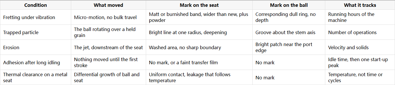
Two of these are easy to confuse and worth separating explicitly. A valve that has been idle for a long time can also arrive at its first stroke with a torque peak and a leak, but that is adhesion, and adhesion leaves no mark at all: the surfaces were in contact and never slid. Fretting requires sliding, however small, and sliding always leaves a band. If the seat is polished across a wide arc, the valve has been moving. If it is untouched and the valve is still stiff, the valve has been still.
What to specify so the joint cannot slip
Three decisions in the specification change the outcome, and none of them is about the seat material.
Support the ball or preload the seat. On a line with a pulsating machine, the floating design is the one where the ball has nothing holding it but the seats, and the trunnion design is the one where the ball is held and the seat moves instead. If the trunnion is chosen, the seat should be spring-loaded, so that contact is maintained when the pressure ripple falls away. A dead seat with no spring has nothing to keep it against the ball between pulses.
Take the side load off the packing. A stem with a bushing below the packing, and an ISO 5211 mounting pad that carries a machined bracket rather than a welded stub, is the structural answer. Where the actuator is heavy, the actuator bracket should be supported at its outboard end, so that the stem is not the only thing between the mass and the pipe.
Retain what is left of the preload. Thread locking or spring washers on the bracket bolts and on the body joint, a stem packing type that tolerates side load, and a trunnion bearing arrangement that carries the ball's weight and the pressure thrust on separate paths, all reduce the amount of movement available for the joint to use. None of these makes a valve immune to a badly supported actuator. They decide how much of the vibration reaches the seal.
What to check on a valve that is already running
Five checks, all of them cheap, and all of them in places a normal inspection skips because nothing is supposed to happen there.
Lift the actuator bolts and look at the pad. A polished or rusty patch under the heads, or a bright ring around the spigot, means the joint has been moving. Slack the gland nuts and look at the gap: if it is not even all the way round, the stem is being pushed sideways and the packing is being asked to act as a bearing. Pull the packing and look at the stem for a polished ring at the packing line. Open the cavity and look for powder on the cavity floor and around the seat carrier. And find a twin valve on a quiet line, because that is the only control available: if the twin has none of these marks, the marks belong to the machine and not to the batch.
The last item is the record. Maintenance systems count operations, because operations are what a valve is supposed to do. This failure has no operations, and it will never appear in a cycle count. What it appears in is the running hours of the pump or compressor that shares the line, and that is the number to put next to the failure when it is written up.
Why J-VALVES builds for the load path, not only for the seal
J-VALVES builds floating ball valves from 1/2 inch to 8 inch and trunnion mounted ball valves from 2 inch to 56 inch, DN15 to DN1400, in ASME Class 150 to 2500, with soft seats in PTFE, RPTFE and PEEK and metal seats with hardfacing where the duty asks for them. Both families are offered with spring-loaded seats, stem bushings, and a machined ISO 5211 pad, and the bracket, the stem support and the seat spring are agreed on the drawing rather than at the site. Shell tests are run at 1.5 times and seat tests at 1.1 times the rated pressure to API 598 and ISO 5208, with EN 10204 3.1 certificates for body, ball and stem.
A valve cannot be designed to be immune to a line that shakes. It can be designed so that the shaking arrives at a part that is sized to take it, and so that the parts which are not sized to take it are not in the load path. That is what the pad, the bushing and the spring are for, and it is worth asking for them by name.
Frequently Asked Questions
Can a ball valve wear out without ever being operated? Yes. Seat load, stem packing and the body joint are all held by preload, and preload is lost by movement rather than by use. A pressure ripple from a pump or compressor moves the ball against its seats, or the seat in its pocket, by an amount too small to see, and the contact band frets. The valve can be years old with a handful of operations and still show a worn band and oxide powder.
Is a trunnion valve immune because the ball is on bearings? No, it moves the problem rather than removing it. The ball is fixed, so the ball-to-seat contact is quieter, but a spring-loaded seat is a piston in a pocket, and it slides when the pressure behind it changes. The wear then appears on the pocket bore and on the seat's secondary seal, which is a place that is only visible after the seat is removed.
Why does the packing leak on the side away from the actuator? Because a heavy actuator on a bracket loads the stem sideways. The packing is compressed harder on the loaded side and relieved on the opposite side, and the relieved side is the leak path. Tightening the gland closes it briefly and increases the side load, so the leak returns.
Would a stronger bracket solve it? It helps, and it has to be checked against the mass it carries rather than chosen by size. A stiff bracket raises the natural frequency of the actuator-and-bracket assembly away from the running speed of the machine, and a supported outboard end stops the stem from being the only load path. A bracket that is merely thick, and unsupported at its outer end, can still put the same bending into the stem.
What single record makes this failure visible in hindsight? Running hours of the machine on the line, kept next to the valve's cycle count. Fretting damage tracks time under vibration, not operations, so a valve with few cycles and a worn band only makes sense when the two records are read together.


