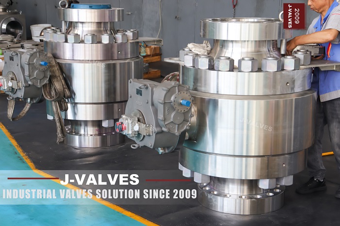
Two DN300 Class 900 ball valve bodies arrived on the same pallet, from the same mill, with the same grade on the certificate and the same results on the chemical analysis. Both had passed radiography at the level called for in the purchase order. Both were dimensionally within tolerance at the flange faces. One held its shell proof at 1.5 times the rating without a weep. The other developed a slow seep at the body neck that took four hours to become visible, and it appeared only on the second pressurisation, after the first had been released. Nobody could explain it from the paperwork, because the paperwork was identical.
The difference was in the two words that the datasheet had not used, and in a geometry that no film can interrogate. Casting and forging are usually presented as a cost decision, or as a strength decision. In a ball valve they are mainly a decision about how much of the pressure boundary is inaccessible to every inspection method you are paying for. This article is about which defects each method owns, where the shape of a valve body defeats them all, and what an acceptance level is actually worth when it is written into a purchase order.
1. What the two routes actually change
The material properties on the certificate are nearly the same, and that is precisely why the certificate is not the answer. A216 WCB is specified at 485 megapascal tensile and 250 megapascal yield; A105 forging is specified at the same 485 and 250. The difference is not in the allowable stress line, it is in how the metal got there.
Attribute | Cast body | Forged body |
|---|---|---|
Solidification | Gravity fill into a sand mould; shrinkage porosity concentrates at thermal centres, typically the neck and the seat pocket wall | Solid ingot or billet worked under pressure; porosity is welded shut by deformation along the grain flow |
Grain structure | As cast, coarse and equiaxed unless normalised; properties vary with section thickness | Refined and directional; toughness is best along the flow line and worst across it |
Wall thickness control | Pattern wear, moulding tolerance and core shift all consume the nominal wall before any pressure calculation begins | Held closely after machining, because there is no mould tolerance to absorb |
Practical size limit | No upper limit in principle; the economics improve with size | Forging press and billet size set a ceiling, and the route becomes uneconomic beyond roughly DN300 to DN400 in a ball valve body |
Cost crossover | Cheaper per kilogram at large size and complex shape | Cheaper at small size where the mould cost cannot be amortised |
Dominant defect risk | Shrinkage, gas porosity, sand inclusion, hot tear, and weld repair quality | Laps, seams, forging bursts, and transverse ductility if the reduction ratio was too low |
The weight difference follows from the second and third rows. A cast body designed to guarantee its minimum wall after moulding tolerance, pattern wear and clean up carries 20 to 35 percent more metal than a forged body of the same bore and class, and that extra metal is not evenly distributed, it sits where the casting process needed it.
2. Wall thickness is a tolerance problem before it is a strength problem
A casting drawing specifies a nominal wall, and then three separate allowances eat into it from the outside. Machining allowance takes 3 to 6 millimetres off every machined surface. Dimensional tolerance on a casting is generous by machining standards: at a nominal dimension of 300 millimetres, a common casting tolerance grade gives about plus or minus 1.6 millimetres. And core shift adds a further 1.5 to 3 millimetres of asymmetry, so the wall can be thin on one side and thick on the other without any single dimension being out of tolerance.
Add those together and a casting that appears to have 45 millimetres of wall at the seat pocket may have 38 on one side. If the design calculation used the nominal figure, the margin has already gone before the valve holds any pressure. This is why a pressure class table in a standard and a wall thickness on a drawing are not the same statement, and why an experienced buyer asks for the minimum wall at the thinnest point rather than the nominal wall on the section drawing.
Forged bodies escape most of this because the shape is produced by machining from solid, so the wall is whatever the machinist left. That is the real technical argument for forging at high pressure, and it has nothing to do with the tensile figure on the certificate.
3. The four methods and the defect each one owns
Non destructive testing is often specified as a package, as though more testing were monotonically better. It is not. Each method is sensitive to a different class of defect and blind to the others, and the acceptance criteria are written for the defects that method can see.
Method | Finds | Blind to | Governing reference |
|---|---|---|---|
Visual, after blast or pickling | Surface laps, hot tears, sand adhesion, cold shuts, repair scars, moulding defects | Everything below the skin, and everything inside a cavity | MSS SP-55 for steel castings, with acceptance levels by discontinuity type |
Magnetic particle or dye penetrant | Surface breaking cracks, including very tight ones, and their length and orientation | Any defect more than a millimetre or two below the surface | Method standard for the technique; acceptance by length and by indication density |
Radiography | Volumetric defects: gas porosity, shrinkage, sand and slag inclusion, and misalignment | Tight planar cracks unless they happen to lie nearly parallel to the beam; anything smaller than the image quality indicator | Reference radiographs with severity levels, applied by section thickness band |
Ultrasonic | Planar defects: cracks, laminations, lack of fusion, and internal shrinkage when access allows | Anything the probe cannot reach at a workable angle, and near surface defects inside the dead zone | Separate standards for castings and for forgings, each with graded acceptance |
Two consequences follow. First, an order that specifies radiography and nothing else has bought a volumetric examination of a component whose most dangerous defects, in a pressure boundary, are often planar and tight. Second, an order that specifies ultrasonic testing on a casting without specifying the geometry it will be applied to has bought an examination that may be physically impossible to perform on the surface that matters.
4. A ball valve body is the worst shape in the plant for radiography
Radiography works best on a flat plate of uniform thickness with a defect oriented across the beam. A ball valve body is the opposite of all three. The wall is curved, the thickness changes continuously from the neck to the seat pocket to the flange, and the leak path that matters is usually a shrinkage channel running through the thickest section at the junction where two masses of metal met during solidification.
The sensitivity figure explains the limit. Image quality is normally verified with a hole of 2 percent of section thickness, the familiar 2-2T requirement. On a 50 millimetre wall that hole is 1 millimetre. A shrinkage channel or a hot tear that will weep under 1.5 times the rating can be 0.05 to 0.2 millimetres across, and even when it is oriented favourably, it is far below what the image can resolve. Radiography is excellent at telling you that a casting is grossly unsound. It is poor at telling you that a casting is sound.
Ultrasonic examination is better suited to planar defects, but the seat pocket defeats it in a different way. A shear wave probe needs a coupling surface and a sound path at a known angle, and the pocket is a recessed, curved, interrupted geometry. What usually happens in practice is that the accessible external surfaces get examined and the region that actually leaks does not, which is why a body can carry a clean ultrasonic report and still seep at proof.
5. What an acceptance level means in numbers
An acceptance level is a severity grade applied to a reference set of radiographs, not an absolute statement about soundness. For steel castings up to about 50 millimetres thick, the reference radiographs are graded in five severity levels, from 1, which is nearly free of the discontinuity, to 5, which is heavily affected. Heavier sections use a different reference set for a higher thickness band, and the grades are not interchangeable between them.
The practical effect of moving from level 2 to level 1 on a large casting is a significant increase in rejections at the foundry and therefore in price and lead time, and it does not address planar defects at all. That trade is worth making on a valve that will see cyclic loading or a lethal service. It is largely wasted on a water line at ambient temperature, where the proof test and the wall thickness will decide the outcome.
Piping design handles the same problem with a single number. A casting quality factor of 1.00 applies to a casting that has been fully examined by radiography or ultrasonic, 0.85 to one that has been spot examined, and 0.80 to one that has been visually examined only. A body designed at 0.80 is designed as though its material were a fifth weaker than the same grade fully examined, which is a fair summary of what unreported porosity costs.
6. Weld repair: the number nobody asks for
Almost every steel casting of valve size contains some weld repair, and a repaired casting is not automatically a bad casting. What matters is where the repair is, how large it is, how many there are, and whether the repair itself was examined. The problem is that the repair map is rarely requested.
Four questions turn this into a specification. Is repair permitted on the pressure boundary at all, or only on non critical surfaces? What is the maximum repaired area, expressed as a percentage of the surface, and the maximum number of repairs in one region? Is repair of the seat pocket and the body to bonnet transition prohibited outright, which is the usual position for a trunnion mounted high pressure body? And after repair, is the area re examined by the same method and to the same level as the original casting, with the repair documented in the certification package?
One further point applies to stainless bodies. A weld repair on CF8M changes the local chemistry and can sensitise the heat affected zone, so the repair should be followed by solution annealing or at minimum by a penetrant examination plus a ferrite check, and the repair area should be included in the PMI coverage rather than excluded from it.
7. Heat treatment, delivery condition and the hardness cap
Delivery condition is a separate line on the purchase order and it is often left to the mill. A216 WCB is normally supplied as cast and may or may not be normalised; A105 is supplied as forged and A105N is the normalised variant, and the N is not decoration. Normalising refines the grain, improves toughness and reduces the scatter in properties between a thin flange and a thick neck.
Post weld heat treatment becomes relevant as soon as two conditions appear: a heavy section, or a hardness limit. Where NACE MR0175 applies, the cap is 22 HRC on the pressure boundary, and a carbon steel body that has not been heat treated after repair can exceed it locally without any chemistry being out of specification. The usual treatment window for carbon steel is 595 to 675 degrees C with a hold of about one hour per 25 millimetres of thickness, and the resulting hardness should be measured, not assumed.
For low temperature service the question moves to impact testing, and the grade changes rather than the heat treatment: WCB is qualified with impact testing at minus 29 degrees C when the purchase order asks for it, and below that the material becomes LCB or LCC at minus 46 degrees C. A datasheet that specifies WCB and a service temperature of minus 40 degrees C has specified a combination that cannot be certified, however good the foundry.
8. Where the proof test does the work that film cannot
The shell test at 1.5 times the rating is usually described as a strength test. In a ball valve body it is mainly a leak path test, and it is the only examination that loads the pressure boundary in the direction a leak has to travel.
That is why the seep in the opening story appeared on the second pressurisation and not the first. A tight shrinkage channel holds until the metal has been stressed once, the channel surfaces have been slightly displaced, and the second application finds a path that the first did not. A single pressurisation is a weaker test than the same pressurisation repeated, and for heavy wall castings a hold long enough for a weep to become a droplet is worth more than an extra film.
It is also why the test medium and its chloride content belong on the purchase order. Water at 50 grams per litre of chloride, left in a body over a shutdown, has started a corrosion cell inside a valve that will be installed a year later, and the resulting pitting will be attributed to the service rather than to the test.
9. What to write in the purchase order
The clauses that decide the outcome are short, and none of them is exotic. Product form and grade together, with the forging reduction ratio stated if the body is forged, because a ratio below about 3 to 1 leaves transverse ductility that no certificate will mention. Minimum wall at the thinnest point, with the measurement location named. The NDT method, the coverage, the reference standard and the acceptance level, each named separately rather than as a package. The repair policy, in the four questions above. The heat treatment condition and the hardness limit with the measurement method. The impact test temperature if the service requires it. And the documentation list, at EN 10204 3.1 for the pressure boundary, with PMI coverage defined by component rather than by valve.
A purchase order carrying those seven items costs an hour to write and removes most of the arguments that follow a failed proof test, because in almost every such argument the honest answer is that the requirement was never written down.
10. Sourcing the body, not just the certificate
J-VALVES supplies ball valve bodies in both routes: forged A105 and A350 for the smaller and higher pressure sizes, cast A216 WCB, A352 LCB and CF8M above them, from a half inch to 56 inch and DN15 to DN1400, in ASME classes 150 up to 2500, across a service window of minus 196 to 650 degrees C. Shell proof is 1.5 times the cold rating and seat proof 1.1 times, with the medium, direction and chloride limit recorded. Minimum wall at the thinnest point, NDT method and acceptance level, repair policy and hardness can all be fixed in the enquiry, and an enquiry that states them comes back with a priced response inside three working hours.
11. Frequently Asked Questions
Is a forged ball valve body stronger than a cast one?
Not in the sense the certificate suggests, because A216 WCB and A105 are both specified at 485 megapascal tensile and 250 megapascal yield. The real difference is the wall thickness that survives manufacturing. A casting consumes part of its nominal wall on moulding tolerance, pattern wear, machining allowance and core shift, so a casting designed to guarantee its minimum wall carries twenty to thirty five percent more metal. Forging wins at high pressure because the wall is whatever was machined, not because the allowable stress is higher.
What does radiography at level 2 actually detect?
Volumetric discontinuities above the image quality threshold, which is normally a hole of two percent of section thickness. On a fifty millimetre wall that is a one millimetre feature. Gas porosity, shrinkage and sand inclusion of that size are found reliably; a tight shrinkage channel or hot tear fifty to two hundred microns across, which is what actually weeps at proof, is below the resolving limit even when favourably oriented. Radiography is a good test for gross soundness and a poor test for leak tightness.
Should I specify radiography or ultrasonic testing on a valve body?
They find different defect classes, so the answer depends on what you are afraid of. Radiography suits volumetric defects in thinner, simpler sections. Ultrasonic suits planar defects in heavy sections, but needs a coupling surface and a sound path at a known angle, and the seat pocket of a ball valve often provides neither. In practice the strongest combination for a high pressure body is surface examination of the accessible pressure boundary, ultrasonic on the heavy sections that can be accessed, and a proof test held long enough to let a weep develop.
Is weld repair on a valve casting acceptable?
It is common and it is permitted, provided four things are controlled: whether repair is allowed on the pressure boundary at all, the maximum repaired area and the number of repairs in one region, an outright prohibition on the seat pocket and the body to bonnet transition, and re examination of the repair by the same method and level as the original casting with the map documented. For stainless bodies the repair also needs a ferrite check and inclusion in the PMI scope, because the local chemistry has changed.
Why did a body pass its first shell test and seep on the second?
Because a tight shrinkage channel can hold until the metal has been loaded once. The first pressurisation slightly displaces the channel surfaces and opens a path that the second application finds. This is why a single short pressurisation is a weaker test than a repeated one, and why heavy wall castings benefit from a hold long enough for a weep to become a visible droplet. It is also the reason a clean radiographic report and a passing proof test are not the same claim about a body.