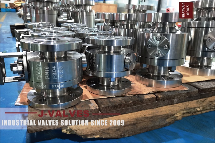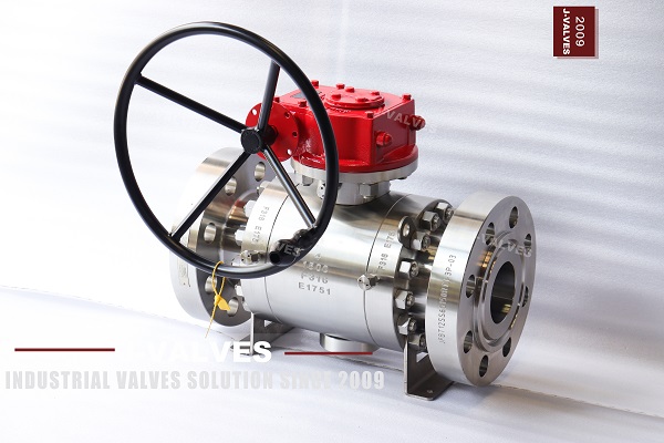


Super-large diameter welded ball valves are crucial components in various industrial applications, including oil and gas pipelines, petrochemical plants, and power generation facilities. These valves are designed to provide reliable flow control and tight sealing under extreme pressure and temperature conditions. The manufacturing process of such valves involves sophisticated welding technology and stringent quality control measures to ensure their durability, performance, and safety.
The welding process for super-large diameter ball valves typically involves the use of advanced techniques such as Gas Tungsten Arc Welding (GTAW) and Gas Metal Arc Welding (GMAW). GTAW is preferred for its precision and ability to produce high-quality welds with minimal distortion, while GMAW is used for its higher deposition rates and efficiency in welding thick sections.
(II) Pre-Welding Preparation
Before welding, the valve components must undergo thorough cleaning to remove any contaminants such as oil, grease, and dust. This ensures that the welds are free from impurities that could compromise their integrity. Additionally, the welding joints are precisely aligned to ensure proper fit-up and reduce the risk of welding defects.
(III) Welding Parameters
Optimal welding parameters, including current, voltage, and travel speed, are carefully selected based on the material properties and thickness of the valve components. Preheating and interpass temperature control are also essential to prevent cracking and ensure uniform heat distribution. For example, in the welding of thick-walled valve bodies, a preheating temperature of around 150°C to 200°C is often recommended to reduce the risk of hydrogen-induced cracking.
(IV) Post-Weld Heat Treatment (PWHT)
PWHT is a critical step in the welding process for super-large diameter ball valves. It helps to relieve residual stresses, improve the mechanical properties of the weld, and enhance corrosion resistance. PWHT is typically performed in a controlled furnace environment at temperatures ranging from 600°C to 700°C, followed by slow cooling to room temperature.
Visual inspection is the first step in quality control, where the weld appearance is examined for defects such as incomplete penetration, undercutting, porosity, and cracks. The welds should have a uniform appearance, smooth transitions, and be free from any visible imperfections.
(II) Non-Destructive Testing (NDT)
Non-destructive testing methods are employed to detect internal defects without compromising the integrity of the weld. Common NDT techniques include:
Ultrasonic Testing (UT): This method uses high-frequency sound waves to detect flaws within the weld. It is highly effective in identifying internal discontinuities such as porosity, inclusions, and lack of fusion.
Radiographic Testing (RT): X-ray or gamma-ray imaging is used to inspect the weld for internal defects. This technique provides a detailed view of the weld’s internal structure and is particularly useful for detecting porosity and inclusions.
Magnetic Particle Testing (MT): This method is used to detect surface and near-surface defects in ferromagnetic materials. Magnetic particles are applied to the weld surface, and any discontinuities will cause the particles to form visible indications.
(III) Dimensional Inspection
Dimensional inspection ensures that the valve components meet the specified tolerances. This includes checking the dimensions of the valve body, flanges, and other critical parts using precision measuring tools such as calipers, micrometers, and coordinate measuring machines (CMM).
Functional testing is performed to verify the performance and reliability of the ball valve. This includes:
Pressure Testing: The valve is subjected to a pressure test to ensure it can withstand the maximum operating pressure without leakage. The test pressure is typically 1.5 times the rated working pressure.
Seal Testing: The valve is tested for leakage by applying a sealant and pressurizing the system. The seal integrity is verified by checking for any signs of leakage at the valve seat and stem.
Cycle Testing: The valve is cycled multiple times to ensure smooth operation and verify that the actuation mechanism functions correctly.