

CHINA J-VALVES Offers Various High-quality I ndustrial Ball Valves
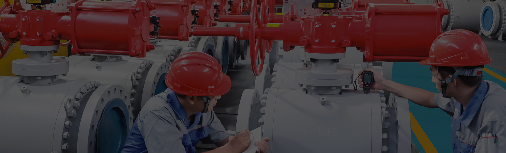
J-VALVES, a distinguished professional ball valve manufacturer rooted in China, takes pride in its extensive product portfolio. Our offerings span a wide range, including trunnion-mounted ball valves, floating ball valves, high-temperature ball valves, high-pressure ball valves, metal-sealed ball valves, ultra-low temperature ball valves, DBB ball valves, Three-way And Four-way Ball Valve, and fully welded ball valves. Each product is a testament to our commitment to precision engineering and reliable performance. Meticulously crafted, they are designed to not only meet but exceed the most stringent industrial demands, ensuring stable operation even under extreme conditions. This enables us to provide our clients with high-value services and makes our valves widely sought-after in industries.
Product Category
Contact Us


Pressure Class: ASME Class 900 / 1500 / 2500
Body Material: A105 forged, WCB cast, A182 F316, F51 duplex
Ball & Stem: A182 F316 with ENP or hard chrome
Seat Material: PTFE, RPTFE, PEEK or metal to metal
End Connection: Flanged RF / RTJ, butt weld, hub
Operation: Gear, pneumatic or electric actuator
Design Standard: API 6D / ISO 14313, ASME B16.34
Test Standard: API 598, shell 1.5x and seat 1.1x
Fire Safe: API 607 / API 6FA
Material Certificate: EN 10204 3.1 with heat number traceability
Temperature Range: -29 C to +200 C, trim dependent
-
BV 2500LB
-
J-VALVES
Overview of the J-VALVES High Pressure
Trunnion Mounted Ball Valve
The J-VALVES high pressure trunnion mounted ball valve is built for pressure classes where a floating ball geometry is no longer practical. It covers sizes from 2 inch (DN50) to 56 inch (DN1400) and pressure classes Class 900 (150 bar), Class 1500 (250 bar) and Class 2500 (420 bar). Every valve is designed to API 6D / ISO 14313 and constructed to the wall thickness, face-to-face and end connection limits of ASME B16.34, with PSL3 full heat number traceability applied to all pressure-retaining parts.In a floating ball valve line pressure forces the ball onto the seat, so seat load grows with bore and pressure. The trunnion mounted design fixes the ball on upper and lower bearings; the ball does not float onto the seat. Seat sealing comes from spring preload plus line pressure on the seat face, keeping torque predictable across the full pressure range.
The valve isolates high pressure gas gathering, wellhead manifold, compressor stations, process lines, metering skids and pipeline block valve stations. Sour service versions are supplied with NACE MR0175 / ISO 15156 compliant materials.
Design and Construction
The ball is supported on trunnion bearings at the top and bottom, so radial and thrust loads from line pressure are carried by the body and the bearings instead of by the seats. This removes the pressure-squared seat load that limits floating ball valves and holds operating torque within the envelope of gear, pneumatic and electric operators.
Seats use a spring preloaded arrangement with either a single piston effect (SPE) or double piston effect (DIB) profile. In the SPE arrangement line pressure assists sealing on one seat and relieves the other, while DIB seals on both seats in either flow direction and enables double block and bleed isolation. Both seat types are fitted with sealant injection fittings so that a sealant can be pumped into the seat area if the primary seal is damaged by solids or wire.
The body cavity is connected to cavity relief, drain and vent connections. When trapped fluid in the cavity heats and expands, the relief path limits pressure to a safe value instead of overstressing the body. A drain and vent point allows the cavity to be emptied and depressurized before maintenance.
The stem is blow-out proof, retained below the bonnet shoulder and sealed by graphite packing backed by a live-loaded gland. An anti-static device connects the ball, stem and body to maintain electrical continuity through the valve.
Fire safe behaviour follows API 607 and API 6FA. If the soft seat is destroyed by fire, the secondary metal seat and the graphite stem seal maintain a seal until the line can be shut down. End connections are flanged RF or RTJ, butt weld or hub type, machined to ASME B16.5, ASME B16.47 and ASME B16.10 dimensions.
Material Options
The body is offered in A105 forged steel, WCB cast steel, A182 F316 stainless steel and F51 duplex stainless steel. Forged A105 and A182 F316 are preferred for Class 2500 and small bore because forging gives cleaner grain flow and better resistance to high hoop stress; sizes 4 inch (DN100) and above use the WCB cast body to keep weight and cost reasonable within ASME B16.34 wall limits.
The ball and stem are A182 F316 as standard, finished with electroless nickel plating (ENP) or hard chrome to reduce friction and resist scoring. Seat inserts are PTFE, RPTFE, PEEK or metal to metal by temperature and fluid; PTFE and RPTFE cover the low to mid range, PEEK extends the upper limit, and metal to metal seats suit abrasive or fire-exposed duty. Temperature range is -29 C to +200 C, set by the seat and seal selection.
F51 duplex is chosen where chloride and strength are both concerns, such as offshore and sour gas gathering, for its resistance to stress corrosion cracking. For sour service the full set is qualified to NACE MR0175 / ISO 15156 and documented with EN 10204 3.1 certificates.
| Component | Standard Material | Optional Upgrade | Service Notes |
|---|---|---|---|
| Body | WCB cast / A105 forged | A182 F316, F51 duplex | Forged preferred for Class 2500 and bore below 4 inch (DN100) |
| Ball | A182 F316 | ENP or hard chrome surface | Hard chrome resists scoring under high seat load |
| Stem | A182 F316 | ENP surface | Blow-out proof, anti-static connected |
| Seat | PTFE | RPTFE, PEEK, metal to metal | Choice follows temperature and fluid |
| Stem seal | Graphite packing | Live-loaded gland | Backed by anti-static device |
| Sealant fitting | A105 / A182 F316 | SS316L pin and check | Seat and stem injection points |
| Bolting | A193 B7 / B16 | A320 L7 | Spiral wound gasket at body joint |
Technical Specifications
The table lists the standard technical envelope of the valve. Values apply to the standard trim and may shift when the seat, end connection or actuator is changed per the order specification.
| Item | Value |
|---|---|
| Size range | 2 inch (DN50) to 56 inch (DN1400) |
| Pressure class | Class 900 (150 bar), 1500 (250 bar), 2500 (420 bar) |
| Design standard | API 6D / ISO 14313, ASME B16.34 |
| Body material | A105 forged, WCB cast, A182 F316, F51 duplex |
| Ball and stem | A182 F316, ENP or hard chrome |
| Seat material | Nylon, DEVLON,PEEK, metal to metal |
| End connection | Flanged RF / RTJ, butt weld, hub |
| Operation | Gear, pneumatic, electric |
| Temperature | -29 C to +200 C (by trim) |
| Shell test | API 598, 1.5x rated pressure |
| Seat test | API 598, 1.1x rated pressure |
| Fire safe | API 607 / API 6FA |
Standards and Compliance
The valve is designed and inspected against the standards that govern pipeline and process isolation equipment. The primary design basis is API 6D / ISO 14313 for pipeline valves, with pressure, wall thickness and end-to-end dimensions controlled by ASME B16.34, ASME B16.10, ASME B16.5 and ASME B16.47. Seat and shell testing follow API 598, and fire testing follows API 607 and API 6FA so that a destroyed soft seat still leaves a sealing path.
For European installations the valve can be supplied with PED 2014/68/EU documentation, and for hazardous area mounting the actuator interface is prepared to the flange and drive dimensions of ISO 5211 for ATEX rated operators. Low emission shaft sealing is arranged to ISO 15848-1 requirements where the duty calls for it. Sour service material compliance is to NACE MR0175 / ISO 15156, and every pressure-retaining part carries an EN 10204 3.1 material certificate with its heat number linked to the PSL3 record.
| Requirement | Standard | Supplied |
|---|---|---|
| Pipeline valve design | API 6D / ISO 14313 | Yes |
| Pressure and dimension | ASME B16.34, B16.10 | Yes |
| Flange and hub ends | ASME B16.5, B16.47 | Yes |
| Seat and shell test | API 598 | Yes |
| Fire safe test | API 607 / API 6FA | Yes |
| Sour service material | NACE MR0175 / ISO 15156 | Optional |
| Material certificate | EN 10204 3.1 | Yes |
Manufacturing Process
J-VALVES operates the process chain for this valve in house. Cast bodies start with casting mould and pour control so that the WCB and duplex castings hold the required wall thickness and surface condition. Forged A105 and A182 F316 bodies are cut and shaped from qualified bar and billet stock. All pressure-retaining faces, seat pockets, trunnion bores and end connections are produced on CNC machining centres to hold the seat concentricity and the face-to-face dimensions of ASME B16.10.
After machining the valve moves to assembly, where the trunnion bearings, spring preloaded seats, ball, stem and sealant injection fittings are built up and torqued to the controlled procedure. Hydrostatic and seat testing is carried out on the test bench, and the operating torque of each gear, pneumatic or electric actuator is measured and recorded. The valve is then coated, marked with its heat numbers and prepared for export packaging. Third party inspection can be arranged on request at any of these stages. Dimensional checks are taken at machining and after assembly to confirm seat concentricity and face-to-face length. Coating thickness and the export wooden case follow the same procedure so the valve arrives protected.
Quality Control and Testing
The valve passes an eight step inspection sequence before it leaves the plant. Each step is recorded so that the test report and material certificates form a complete document package for the order. The sequence tracks the part from raw material to finished valve and links every measurement to the heat number on the PSL3 record.
| Step | What Is Checked | Standard or Acceptance |
|---|---|---|
| Incoming material | Heat number, chemistry, mill cert | EN 10204 3.1, PSL3 |
| Machining dimension | Bore, seat pocket, face-to-face | ASME B16.10, drawing |
| Assembly and function | Torque, open-close, injection | Smooth, no bind |
| Shell strength test | Body and bonnet at 1.5x | API 598, no leak |
| Seat test | Both seats at 1.1x | API 598, ISO 5208 |
| NDT and hardness | Weld, body, trim hardness | Procedure, recheck |
| Coating and marking | Film, heat number tag | Spec, legible |
| Final and documents | Function, cert package | EN 10204 3.1 set |
Shell strength testing pressurises the body and bonnet to 1.5 times the rated pressure with water and holds the pressure while the joints are inspected for weeping. Seat testing applies 1.1 times the rated pressure on each seat in both directions and checks for leakage past the seat. Where the order calls for it, low temperature or fire test witness is arranged and noted in the document package.

Applications and Industry Service
The class 900 ball valve and the higher class 1500 and 2500 versions are specified where isolation must hold against high line pressure without the torque penalty of a floating ball. In high pressure gas gathering and wellhead manifold service the double block and bleed arrangement lets an isolated section be vented and proved safe before work begins. Compressor stations use the valve as suction and discharge isolation that closes against full system pressure.
Pipeline block valve stations and metering skids rely on the spring preloaded seats and sealant injection ports to keep sealing when the fluid carries sand, scale or hydrate solids. The api 6d psl3 ball valve build is used where the pipeline specification requires full material traceability and documented testing. A metal seated high pressure ball valve version with metal to metal seats is available for abrasive or high temperature duties within the -29 C to +200 C range. Sour gas and offshore gathering lines select the F51 duplex or NACE compliant trim to resist cracking. The class 2500 ball valve suits wellhead and compression duties near the limit of lower classes, while class 900 and class 1500 builds cover battery limits and the mid high pressure range.
Installation, Operation and Maintenance
Before installation the flange faces or weld ends must be cleaned and the bore inspected for foreign objects. Flanged joints are made up with the specified gasket and bolt torque, and butt weld ends are aligned within the root gap and fit-up limits of ASME B31.3, ASME B31.4 or ASME B31.8 as applicable. The actuator mounting follows ISO 5211 flange and drive dimensions so that gear, pneumatic and electric operators fit without an adapter.
During operation the cavity relief, drain and vent connections should be kept clear. If a seat begins to pass, the sealant injection fitting allows sealant to be pumped into the seat ring to restore sealing until a planned shutdown. The live-loaded graphite gland holds stem sealing with minimal adjustment; if stem leakage appears, the gland can be tightened within its set range.
For planned maintenance the valve is isolated, the cavity drained and vented, and the seats inspected. Spring preloaded seats and the anti-static path are checked, and any worn sealant fitting check valve is replaced. Re-torque the body bolts to the procedure and re-test the seat at 1.1 times rated pressure before returning the valve to service. Confirm the actuator indicator shows the correct position before pressurising, and keep the cavity relief path clear so trapped fluid can vent.

How to Specify and Order
To place an order, state the size in inch and DN, the pressure class among Class 900, 1500 and 2500, the end connection type, the body and trim material, the seat type and the operator. Indicate whether double block and bleed, sealant injection and cavity relief are required, and whether NACE MR0175 / ISO 15156 material or PSL3 documentation is needed. Quote the pipeline design standard, usually API 6D, and the relevant ASME B31 code for the piping system.
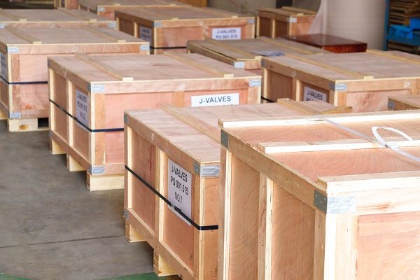
Standard specifications are accepted from a minimum order of one piece, and standard specifications are delivered in a regular lead time of 2 to 4 weeks. The delivery file includes the EN 10204 3.1 material certificate, a dimensional report, a test report carrying the torque record, a coating report and a packing list. Export packaging uses a wooden case with the bore plugged and the flange face protected. Third party inspection can be arranged on request, and the witnessed results are added to the final document package.
About High Pressure Trunnion Ball Valve | Class 900-2500 FAQ
Q: What is the maximum pressure class for a trunnion mounted ball valve?
A: J-VALVES supplies trunnion mounted ball valves up to ASME Class 2500. Class 1500 and 2500 valves are normally supplied in a forged body with a gearbox or actuator, and are tested with the shell at 1.5 times and the seat at 1.1 times the rated pressure.
Q: Why use a trunnion design instead of a floating ball at high pressure?
A: Above roughly Class 600 the force pushing a floating ball into the downstream seat becomes large enough to raise torque and wear. A trunnion design carries the ball on bearings so the seat load is controlled by spring pre-load and line pressure, which keeps torque predictable and extends seat life.
Q: Can you supply a high pressure trunnion valve for sour service?
A: Yes. For H2S service the body, ball, stem and seat materials are supplied to NACE MR0175 / ISO 15156 with hardness control, and the material certificate records the hardness results for each heat number.
Q: Do you provide sealant injection and cavity relief?
A: Sealant injection fittings on both seats and on the stem are standard on Class 900 and above. Body cavity relief, drain and vent connections are supplied to the line specification and can be plugged or fitted with a needle valve.
Hot Products


News
Floating Ball Valve Applications: Working Principle, Selection Guide & Typical Services
Learn how a floating ball valve works, where it's used in oil & gas, chemical and offshore service, and how to choose between a floating and a trunnion ball valve.
Read More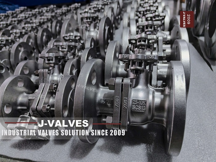
Trunnion Mounted Ball Valves in Offshore Service: How Fixed-Ball Design Handles FPSO, Subsea and High-Pressure Duty
Trunnion ball valves for offshore service: how fixed-ball design manages FPSO, subsea and high-pressure duty, plus material, standard and RFQ selection tips.
Read More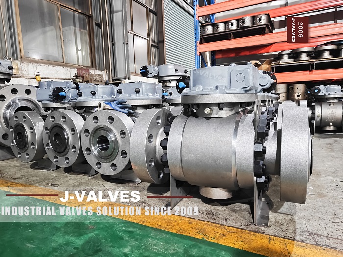
Inside The Valve Factory: 3PC Trunnion Ball Valve Manufacturing
Step‑by‑step factory tour of 3‑piece trunnion mounted ball valve production. Manufactured per API 6D, for oil & gas, chemical high‑pressure pipeline projects. Contact J‑VALVES for quotes.
Read More
Factory 3PC Trunnion Ball Valves Show Professional Manufacturing Capability
I. Mass‑Production Real‑Scene Shows True Industrial Valve CompetenceIn J‑VALVES manufacturing workshop, large quantities of finished 3‑piece (3PC) trunnion‑mounted ball valves are neatly stacked on wooden pallets, with completed coating and protected flange ends, real‑life deliverable goods for larg
Read More