

Structure and Working Principle
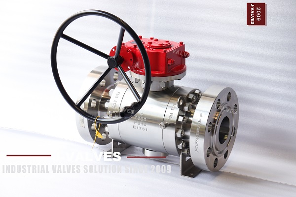
A trunnion mounted ball valve is built from seven functional groups. The body is usually a three-piece bolted construction: a centre body housing the ball, two end connectors facing the pipe flanges, and a ring of high tensile studs at each interface, a split that lets the ball and seats be removed as a set without cutting the line. The ball is the only moving closure member and carries a through bore close to the pipe internal diameter. Upper and lower trunnion shafts hold the ball in the centre of the cavity, supported by bearings fitted at the top and bottom of the body; bearing material may be Devlon, PEEK or metal bushings, and its job is to let the ball rotate 90 degrees about a vertical axis with no lateral displacement. The floating seats are a pair of annular assemblies, each backed by disc springs or coil springs. Those springs supply the initial sealing force at low pressure, and line pressure admitted behind the seat then adds a self-energising force on top. The stem passes through the upper body into the gearbox and transmits the turning moment to the ball. Sealing is a system of three independent lines of defence: the seats, the stem packing and the static body seals. Finally, emergency sealant injection fittings at the seat and stem provide a response for an unexpected loss of sealing.
The way sealing is established differs from a floating ball valve. In a floating design the ball rests freely between the two seats and line pressure pushes the whole ball downstream into the downstream seat; the higher the pressure, the greater the thrust, and seat contact stress and operating torque climb with it. In a trunnion mounted design the ball is locked in the centre by the trunnion shafts, and instead the spring-loaded floating seats are pressed onto the stationary ball, with pressure load passing through the shafts and bearings straight into the body so that the seats carry only the contact stress needed to seal. The result is constant seat loading with even seat wear, torque that no longer climbs with pressure, and two independently floating seats in which either one can seal against pressure from its own side.
What API 6D Requires
The design basis is API 6D, the pipeline valve standard, supported from two other directions by API 608 for metal ball valves and ASME B16.34 for pressure-temperature ratings. The requirement most often left out of a purchase specification is anti-static continuity: the ball, stem and body must remain electrically connected, and the resistance measured with a calibrated meter must not exceed 10 ohms. This test is mandatory and has to appear in the inspection and test plan. Hydrocarbon flow accumulates static charge on the ball and stem, and a discharge is an ignition source; J-VALVES fits stainless steel spring contacts between ball and stem and between stem and body so charge drains into the body and on to the piping earth. Standing alongside it is the blowout-proof stem: the stem must have a shouldered or integrally forged T-head profile, meaning the head diameter exceeds the bore it passes through, and it must be retained by the bonnet or gland nut so that internal pressure can never eject it.
The second group covers fire safety and cavity relief. A valve must pass a fire test to API 607 or API 6FA, for which ISO 10497 is the international equivalent, at roughly 750 to 800 degrees Celsius (1,382 to 1,472 degrees Fahrenheit) for 30 minutes, and still seal afterwards. Soft seats burn away, so a metal-to-metal secondary seat has to be built in as the backup. Cavity relief addresses the space between the two seats that is isolated once the ball closes. If liquid is trapped there and warms up, the resulting cavity pressure can far exceed line pressure and even rupture the body. API 6D limits the cavity differential to no more than 33 percent above the valve pressure rating for design temperatures up to 121 degrees Celsius (250 degrees Fahrenheit), so a relief path is mandatory. J-VALVES offers two seat arrangements. The first is a self-relieving single piston effect seat, where cavity pressure above line pressure lifts the seat off the ball and relieves to the low pressure side. The second is a double piston effect seat, where cavity pressure acts on both the upstream and downstream seats so the valve seals in either direction; with a bleed connection between the seats this delivers DBB double block and bleed. Note the distinction: a single self-relieving seat does not constitute DBB, because DBB requires both seats to seal independently.
The third group sits on materials and verification. Minimum body wall thickness and the allowable stress of the body bolting must both comply with ASME B16.34, and pressure testing follows API 6D and API 598: the shell test is 1.5 times the rated pressure and the seat test 1.1 times. Soft seated valves are held to ISO 5208 Rate A, that is no visible leakage, and metal seated valves default to Rate D unless the contract states otherwise. The J-VALVES published table gives shell test pressures of 3.0, 7.5, 15.4, 23.0, 37.5 and 63.0 MPa (435, 1,088, 2,234, 3,336, 5,439 and 9,137 psi) and seat test pressures of 2.2, 5.5, 11.2, 16.9, 27.5 and 46.2 MPa (319, 798, 1,624, 2,451, 3,989 and 6,701 psi) for Class 150 through 2500, with a uniform air test of 0.6 MPa (87 psi). The valve must also carry permanent marking on the nameplate or body showing the manufacturer, year of manufacture, nominal size, pressure class, body material, trim material and applicable standard. Trim designation and pressure class most often disagree with the purchase order at goods receipt, so they should be checked valve by valve.
Trunnion Mounted versus Floating Ball Valves
The boundary between the two designs is set by pressure and bore together. A floating ball valve is simple, has few parts and costs less to make, and it is the most economical choice for Class 300 and below with bores up to DN200 (8 in). Once pressure reaches Class 600 or the bore passes DN200, the thrust on the ball grows with pressure multiplied by area, and inadequate seat contact stress arrives together with runaway operating torque; at that point the trunnion design is effectively the only workable option. The rule of thumb used across the industry is that a bore above DN200, or a class above Class 600, means a trunnion mounted valve.
Operating torque is the difference most often underestimated. At DN200 (8 in) in Class 300, floating ball breakaway torque is about 60 N·m (44 lbf·ft) and trunnion about 85 N·m (63 lbf·ft), roughly 40 percent higher because the trunnion has to overcome bearing friction. Above Class 600 the relationship inverts: at the same DN200 in Class 600 the floating design reaches about 130 N·m (96 lbf·ft) while the trunnion design sits at about 95 N·m (70 lbf·ft). What matters more is how torque varies with pressure. From zero to design pressure floating torque rises about 70 percent, while trunnion torque moves only about plus or minus 8 percent. That sets the actuator margin: a floating design typically needs 1.7 times design torque, a trunnion design only 1.1 times, and actuators can account for 30 to 50 percent of total valve system cost. Beyond torque, a trunnion design delivers bidirectional sealing and DBB, while a floating ball valve is a unidirectional design that must be installed strictly by the flow arrow.
Selection Parameters
Selection works through seven parameters, the first four fixed by the service and the last three by life and cost. Bore is chosen by back-calculating the Cv needed from design flow and allowable pressure drop and reading it against the Cv table, and the same step decides between full bore and reduced bore: full bore matches the pipe internal diameter, passes pigs and gives the lowest local resistance, while reduced bore uses a smaller ball in the same face-to-face envelope to cut cost where pigging is not required. Pressure class comes from the highest working pressure together with the pressure-temperature rating at design temperature, and the common coverage is Class 150 through 2500. End connections may be RF or RTJ flanges, butt weld ends or API 6A hub connections; high pressure small bore work usually takes RTJ flanges and butt weld ends. Body material is a cross-selection of medium corrosivity, working temperature and pressure class. Seat type trades soft sealing against metal sealing: soft seats seal better but are temperature limited, metal seats take high temperature and abrasion but with a relaxed allowable leakage rate. Bearing and spring materials set the friction coefficient and the usable temperature ceiling. Actuation follows operating frequency and whether remote control is needed.
Material and temperature form the second axis of selection. In this product line J-VALVES offers body material in F304, F316 and F316L forgings, F51 duplex, F53 and F55 super duplex, 6Mo super austenitic stainless steel, and 625 and C276 nickel alloys; ball and stem in F316 with hard chrome or electroless nickel plating, F51, F53 and F55, 6Mo, or Inconel 625 with tungsten carbide coating; the stem additionally in 17-4PH, Inconel 718 and Monel K-500; soft seats in PTFE, RPTFE, PEEK, Devlon and Nylon with metal seats hardfaced in Stellite, tungsten carbide or a nickel based alloy; and springs in Inconel 718, Hastelloy C-276 and 17-7PH. Standard stainless steel bodies cover roughly -29 to +425 degrees Celsius (-20 to +797 degrees Fahrenheit), beyond which the material has to change or low temperature steel with impact testing is required. Sour service containing hydrogen sulphide is governed by NACE MR0175 and ISO 15156, holding material hardness to typically no more than HB 235. Seawater and high chloride service should avoid standard austenitic stainless steel because of pitting and crevice corrosion in low velocity stagnant sections, and should use duplex or super duplex instead. Among soft seats, PTFE is limited to about 200 degrees Celsius (392 degrees Fahrenheit) continuous, RPTFE and PEEK raise that ceiling, and above roughly 400 degrees Celsius (752 degrees Fahrenheit) a metal seat hardfaced with Stellite or tungsten carbide becomes mandatory. Actuator sizing is driven by torque, and API 6D requires rated torque to be measured at design pressure and documented in the data sheet with the pressure-torque relationship for the actuator vendor. J-VALVES runs a flow analysis on every valve and verifies actual torque before dispatch, so actuator selection rests on measured figures.
J-VALVES Manufacturing Advantages
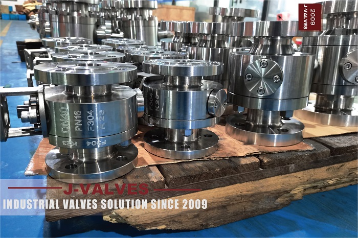
J-VALVES (Zhejiang J-Valves Fluid Equipment Co., Ltd.) has manufactured and exported industrial valves since 2009 from a factory in the Airport New District of the Binhai Industrial Park, Longwan District, Wenzhou, Zhejiang. The plant covers over 15,000 square metres (161,500 sq ft) and employs more than 100 people, including 8 technical engineers who produce 3D and 2D drawings in SolidWorks and AutoCAD and complete mould design in UG, 8 inspectors each with more than 10 years of valve inspection experience, and a production management team that includes a CNC technician with 20 years in industrial valves. Casting, machining, assembly and pressure testing all take place inside the company's own works. This product line covers DN50 to DN1400 (2 in to 56 in) in Class 150 through 2500 (PN16 to PN420), in full bore or reduced bore as required. The 4 in 1500LB F316 valve in the photograph is a routine item from this line, and delivered references in the same family include large bore high pressure pipeline valves and duplex stainless steel valves for sour service.
Quality control is written into specific process steps through four stages. Incoming material is dimensionally checked and put through PMI spectrographic analysis, visual inspection and hardness testing, where PMI is the key means of proving that delivered parts match the material certificates. Machining inspects every part against the drawing for ball roundness, trunnion shaft coaxiality and seat sealing surface roughness. Assembly applies precision fitting, torque control and leakage testing, with torque control aimed directly at seat spring preload and body bolting torque, the former deciding whether initial sealing can be established at low pressure. Dispatch runs the shell and seat pressure tests, flow analysis and leakage detection valve by valve to API 6D, and the test records ship with the goods. Certifications held include API 6D, API 600, API 602, API 607, CE, ISO 9001, ISO 14001, ISO 45001, SIL 3 and ISO 15848, and the company has passed an SGS supplier audit. Commercial terms include an 18 month warranty and a 24 hour response on quality issues, with lead time around 15 working days in the low season. The advantage in this product line is not a peak figure on any one parameter, but that the standard requirements are turned into inspectable process steps: the 10 ohm anti-static rule into continuity measurement after spring contact assembly, the blowout-proof stem into an integrally forged T-head design, low pressure initial sealing into seat spring preload control, and material authenticity into incoming PMI. None of the four is a sampling check, and all four are traceable with the shipment.
Installation, Maintenance and Applications
Installation starts with flow direction and orientation. Even though a trunnion mounted valve seals in both directions, the body still carries a flow arrow and a self-relieving seat has a defined relief direction, so the valve should still go in the specified way round. The gearbox and handwheel should sit where they can be operated and serviced, and buried lines should use an extended stem with a protective housing. Next comes flange make-up: pipe flanges and valve flanges must be parallel and aligned, no additional piping stress may be carried by the body, and any misalignment has to be removed with supports rather than pulled straight by tightening bolts. On RTJ ends the ring gasket material and hardness should be verified, and flange bolts tightened in a cross pattern in stages to the specified torque. Valves of 6 in and above should be lifted from the body lifting lugs, never from the gearbox or handwheel. A DN400 (16 in) Class 600 trunnion ball valve has a body wall of roughly 36 mm (1.42 in) and can weigh around 2.4 tonnes (5,291 lb), so foundation and support capacity should be confirmed before installation.
Maintenance is condition based and, where possible, done online. The design carries emergency sealant injection fittings at the seat and stem, so when a seat loses sealing to particle erosion or a stem seal is accidentally damaged, sealant can be injected to restore sealing temporarily and keep the line running to the next planned shutdown instead of forcing an immediate stop. Top entry versions allow seats and seals to be replaced without taking the body out of the line. Routine checks concentrate on four things: whether the valve completes a full stroke against rated differential pressure, whether the sealant injection passages are clear, whether there is any weeping at the stem packing, and whether the gearbox makes abnormal noise. Applications cluster in four directions. On oil and gas transmission pipelines for mainline isolation and station block service, where classes are commonly Class 600 to 900 and DBB capability is routinely required. On high pressure gathering, water injection and gas injection lines in oil and gas fields, where sand bearing media and high differential pressure demand hardfaced ball and seat surfaces. In high pressure chemical and fertiliser plants on reaction systems and safety interlock loops, where the medium often contains hydrogen and hydrogen sulphide. And in LNG receiving terminals on high pressure send-out and vaporisation systems, where cryogenic materials are required, as well as seawater desalination and high chloride water treatment where duplex and super duplex are needed. Offshore and subsea pipeline systems additionally require valves designed to API 6DSS, and sour gas fields require materials certified to NACE MR0175.
Frequently Asked Questions
What is the difference between a trunnion mounted and a floating ball valve?
The difference is whether the ball is fixed. A trunnion mounted valve locks the ball in the centre of the cavity on upper and lower trunnion shafts, and spring-loaded floating seats are pushed against the stationary ball to seal. In a floating ball valve the ball sits free between the two seats and line pressure pushes it into the downstream seat. As a result the trunnion design has low torque that barely changes with pressure, seals in both directions and suits large bores and high classes, while the floating design is simpler and cheaper for Class 300 and below with bores up to DN200 (8 in).
What do DBB and DPE mean?
DBB means double block and bleed: the upstream and downstream seats each seal independently, so the cavity between them can be vented to prove positive isolation before a pipe section is opened. DPE means double piston effect: cavity pressure acts on both seats at once, so the valve seals in either direction and meets double isolation requirements. The two are related but not identical, and a single self-relieving single piston effect seat does not constitute DBB.
Why does trunnion ball valve torque not rise with pressure?
Because the load path is different. The ball is carried on upper and lower bearings, so the thrust that line pressure applies to the ball passes through the trunnion shafts straight into the body, and the seats only carry the contact stress needed to seal. Measured on DN200 (8 in), floating ball torque rises about 70 percent from zero pressure to design pressure while trunnion torque changes only about plus or minus 8 percent, which is why trunnion valves need only a 1.1 times actuator margin against 1.7 times for floating designs.
What is the anti-static requirement for a trunnion ball valve?
API 6D requires electrical continuity between the ball, stem and body with a resistance not exceeding 10 ohms, measured with a calibrated resistance meter and recorded in the inspection and test plan. J-VALVES fits stainless steel spring contacts between ball and stem and between stem and body so the charge drains into the body and then to the piping earth system.
Which fire-safe standard applies to a trunnion ball valve?
Fire testing follows API 607 or API 6FA, with ISO 10497 as the international equivalent. The test exposes the valve to a flame of roughly 750 to 800 degrees Celsius (1,382 to 1,472 degrees Fahrenheit) for 30 minutes and requires it to remain sealing afterwards. Soft seats burn away in a fire, so a metal-to-metal secondary seat must be present as the backup.
Can a trunnion ball valve seal in both directions?
Yes, and this is the structural difference from a floating ball valve. The two seats float independently, so whichever side carries pressure, that seat is pushed against the ball to seal, and double piston effect seats also satisfy double isolation. A floating ball valve loses its seal under reverse pressure because the ball is pushed away from the downstream seat, so it is a unidirectional design.
Which services suit a stainless steel trunnion ball valve?
Chloride-bearing, sour or cleanliness-critical medium and high pressure services. Seawater, high chloride water and offshore platforms call for F51 duplex, F53 or F55 super duplex, because standard austenitic stainless steel is at risk of pitting and crevice corrosion in low velocity stagnant sections. Sour gas fields require hardness limits per NACE MR0175 and ISO 15156, usually not exceeding HB 235. Cryogenic duty requires low temperature steel with impact testing.
Which standard governs pressure testing of a trunnion ball valve?
Testing follows API 6D and API 598. The shell test is 1.5 times the rated pressure, which for Class 150 through 2500 is 3.0, 7.5, 15.4, 23.0, 37.5 and 63.0 MPa (435, 1,088, 2,234, 3,336, 5,439 and 9,137 psi); the seat test is 1.1 times, at 2.2, 5.5, 11.2, 16.9, 27.5 and 46.2 MPa (319, 798, 1,624, 2,451, 3,989 and 6,701 psi); and the air test is 0.6 MPa (87 psi). Soft seated valves are held to ISO 5208 Rate A, no visible leakage. J-VALVES tests every valve before dispatch and ships the records with the goods.
How is the body wall thickness of a trunnion ball valve determined?
Minimum wall thickness comes from the pressure-temperature ratings in ASME B16.34, and API 6D additionally requires the allowable stress of the body bolting to comply with the same standard. Insufficient wall thickness is one of the least visible defects at goods receipt, because neither visual inspection nor a pressure test exposes it, so it has to be verified against the material certificates and the dimensional inspection report, with physical thickness measurement where required.
Can internal leakage on a trunnion ball valve be repaired online?
Online treatment is worth trying first. The design carries an emergency sealant injection fitting at the seat and stem, so injecting sealant can temporarily restore sealing and keep the line running to the next planned shutdown instead of forcing an immediate stop. Top entry versions allow seats and seals to be replaced without removing the body from the line. If the sealing surface is badly eroded by particles or the ball surface is already damaged, the valve still has to be opened and the internals replaced.