


CHINA J-VALVES Offers Various High-quality I ndustrial Ball Valves
J-VALVES, a distinguished professional ball valve manufacturer rooted in China, takes pride in its extensive product portfolio. Our offerings span a wide range, including trunnion-mounted ball valves, floating ball valves, high-temperature ball valves, high-pressure ball valves, metal-sealed ball valves, ultra-low temperature ball valves, DBB ball valves, Three-way And Four-way Ball Valve, and fully welded ball valves. Each product is a testament to our commitment to precision engineering and reliable performance. Meticulously crafted, they are designed to not only meet but exceed the most stringent industrial demands, ensuring stable operation even under extreme conditions. This enables us to provide our clients with high-value services and makes our valves widely sought-after in industries.
Product Category
Contact Us

-
J-VALVES-Q9347F
-
J-VALVES
Overview of the J-VALVES electric metal sealed trunnion flange ball valve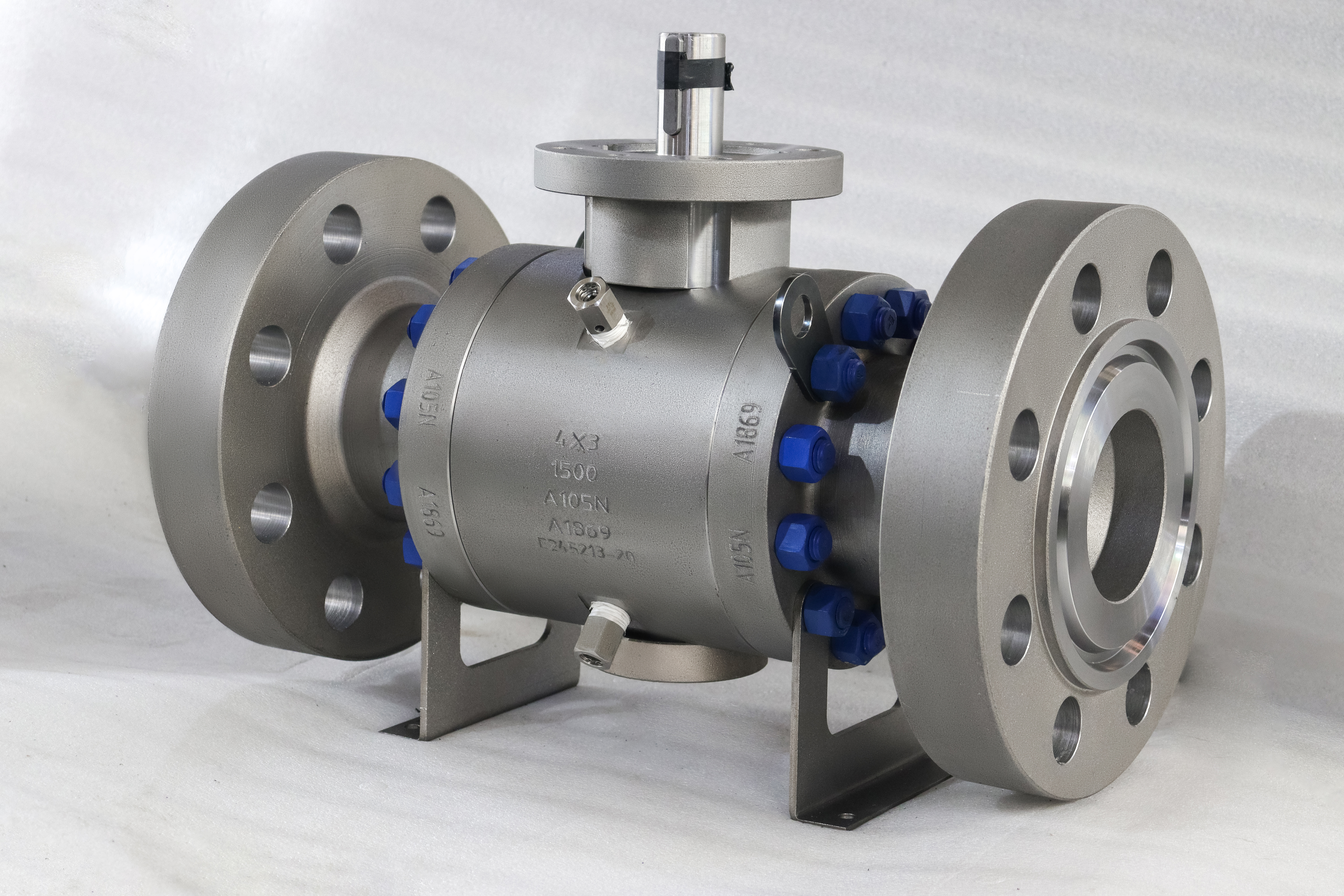
The valve in the photographs is a two and a half inch, Class 2500, forged A105 three piece body with a metal seat and a motor bolted to the top. Everything about the photograph is about the body except the part that will be chosen last and will cause the most trouble: the motor.
An electric actuator is usually bought as if it were an accessory, selected after the valve by matching a size and a voltage. On a metal seated valve at 2500 that order of work is backwards. The torque that decides the motor is not the torque on the bench at ambient; it is the torque needed to break the valve off its seat after it has been closed hot, and the difference between those two numbers is the difference between a motor that works and one that trips on overload every cycle.
The reason is thermal. At temperature the ball grows more than the seat ring around it, because the ball is a solid sphere and the ring is a thin annulus, so the contact band loads up as the valve heats. Add the product that bakes in the band during a long closed period, and the breakaway torque after a cool down can be several times the figure measured at the works.
That is why this page is about selection rather than about construction. The body, the seat and the ends are settled by the line; the motor is settled by a number that has to be calculated for the duty, and a page that lists the actuator as a line item has not done that. Written that way, the assembly stops being a valve with a motor on top and becomes a drive train: a body and seat that produce a torque, a pad that defines the interface, a bracket and coupler that transmit it, and a motor chosen against the torque at the temperature the line actually runs at.
Design and Construction
The body is three pieces, forged, with a metal seat and a trunnion mounted ball. The stem comes up through a short neck to a pad, and the motor sits on a bracket above that pad. Everything that holds pressure is below the pad; everything above it is a drive.
The bracket and the coupler are the two parts that get the least attention and cause the most failures. The bracket sets the height and the bolt pattern; the coupler transmits the torque from the motor shaft to the stem square. A coupler that does not match the stem flats will round them, and the rounding appears first as a dead band at each end of the stroke and then as a valve that will not stroke at all.
The body joints are the maintenance path. With the line isolated, the end pieces come off and the seats and ball are reachable, which on a 2500 class valve is the difference between a repair and a replacement. The motor comes off with four bolts and a coupler, and it does not have to be removed to service the body.
The metal seat is the part that makes the motor selection hard. A polymer seat conforms, so its breakaway torque stays close to its running torque and both stay close to what was measured at assembly. A metal seat does not conform: it is a contact band under load, and that load changes with temperature, with pressure and with how long the valve has been closed.

Material Options
The material list is short because the interesting decision is not here. A105 is the forged carbon steel, F304 and F316 are the stainless options, and the seats are metal with a cobalt based overlay or a carbide. What matters for the motor is not the grade but the pairing and the temperature.
| Part | Material on This Build | What It Decides |
|---|---|---|
| Body and end pieces | Forged A105 on the photographed build; WCB, CF8, CF8M, F304 or F316 in the range | Shell strength and corrosion |
| Ball | F304, F316 or a nickel based alloy | Wear at the band and corrosion |
| Seat | Metal, cobalt based overlay or carbide | Breakaway torque and leakage rate |
| Stem | 17-4PH, F316 or a nickel based alloy | Torque transmission at the drive |
| Bearings | High strength alloy at the trunnion | Whether the ball stays centred under load |
| Ends | Raised face or ring joint flange | The joint at the top of the class range |
| Actuator | Electric, on off or modulating | The failure behaviour and the cycle rate |
The stem grade matters more on an actuated valve than on a manual one, because the motor applies torque at a rate a hand cannot and does it thousands of times. 17-4PH is the usual choice for the drive end: it takes the torque without galling at the square, and it keeps its strength at the temperatures a metal seat implies.
The bearing line is worth a note because it is often confused with the actuator selection. The trunnion bearings carry the ball against the line thrust, and their capacity is a property of the valve rather than of the motor. A valve with adequate bearings turns easily at pressure; a valve with inadequate ones turns easily on the bench and seizes under differential, and no motor setting fixes that.
Technical Specifications
The table keeps the page entries and separates the three properties that decide whether the motor will work: the torque, the duty and the enclosure.
| Item | Value |
|---|---|
| Size on the photograph | DN 65, two and a half inch |
| Size range | Two to 56 inch, DN 50 to DN 1400 |
| Pressure class | Class 150 to Class 2500 |
| Class on the photograph | Class 2500, PN 420 |
| Body | WCB, CF8, CF8M, A105, F304 or F316 |
| Ball | F304, F316 or a nickel based alloy |
| Seat | Metal, cobalt based overlay or carbide |
| Temperature range printed | Minus 196 to plus 540 Celsius |
| Ends | Raised face or ring joint flange |
| Design | ASME B16.34, API 6D, API 608 |
| Test | API 598, API 6D, ISO 5208 |
| Actuator | Electric, on off or modulating |
| Motor duty | Short time, not continuous stall |
The temperature range printed on the page covers a cryogenic build and a high temperature build in one line, which is true of the family and false of any one valve. A minus 196 build has a long stem, low temperature bolting and a seat that does not turn brittle; a 540 build has a metal seat, graphite packing and bolting that keeps its strength. The photographed valve, a 2500 class A105 body, is at the lower end of the high temperature side rather than at either extreme.
The class line is exact and it matters to the motor, because torque rises with class for the same bore. A motor sized for a Class 600 valve of this size will be undersized by a wide margin on a 2500 one, and the mistake is invisible on the bench because an unpressurised valve turns easily at any class.
Standards and Compliance
The documents divide into those that describe the valve and those that describe the motor, and no single document covers both.
| Document | What it fixes | What It Does Not Fix |
|---|---|---|
| API 6D | Valve requirements, fire test, marking | Actuator sizing or duty |
| ASME B16.34 | Wall, material groups, class ratings | The seat pairing or the torque |
| API 608 | Ball valves to DN 600 and Class 600 | A Class 2500 valve |
| API 598 | Shell and seat test acceptance | A breakaway torque figure |
| ISO 5211 | Pad dimensions, bolt circle and drive form | The motor behind the pad |
The 608 line appears on the page and does not belong on this valve. At 2500 class the document's scope has ended, and the ball valve document that covers the class is API 6D. On a page that describes a family from 150 to 2500 it is possible to name both and mean that the factory builds to both; on a quotation for a 2500 valve only one of them applies.
ISO 5211 is the document that does the real work for the assembly, and it is the one buyers look at last. It fixes the bolt circle, the thread and the drive form at the pad, so a bracket is chosen against a pad designation and a coupler against the stem. Without it, every actuator would be a bespoke bracket, and the industry would spend its time machining adaptors.
What no document fixes is the duty. A motor has a duty cycle and a thermal rating, and a valve that is stroked twice a day is a different application from one that is stroked every few minutes. That belongs on the order as a cycle rate, because it decides the motor as much as the torque does.
Manufacturing Process
The body is forged, machined, and assembled with the seat and ball in the usual order: trunnion bearing, ball, seats and springs, end pieces, then stem and packing. What changes on an actuated build is the last few operations, because the pad and the stem square have to be right before the bracket is fitted.
The pad is drilled on a bolt circle referenced to the stem axis, and the stem square is cut after the packing gland face so that the drive is square to the gland rather than to the raw forging. A pad that is off centre puts a side load on the packing every time the valve strokes, and the leak that follows is blamed on the packing rather than on the pad.
The bracket is machined to match the pad on one side and the motor flange on the other, and the coupler is machined to match the stem flats and the motor shaft. Both are simple parts and both are made to drawings that come from two different manufacturers, which is why the interface is standardised rather than negotiated. Written that way, the assembly stops being a valve with a motor on top and becomes a drive train: a body and seat that produce a torque, a pad that defines the interface, a bracket and coupler that transmit it, and a motor chosen against the torque at the temperature the line actually runs at.

Quality Control and Testing
The shell and seat tests are run before the motor is fitted, because the motor has to be off for the seat test on some rigs and because a motor damaged by test water is an unnecessary loss. The acceptance for the seat is the metal seat rate, not zero. Written that way, the assembly stops being a valve with a motor on top and becomes a drive train: a body and seat that produce a torque, a pad that defines the interface, a bracket and coupler that transmit it, and a motor chosen against the torque at the temperature the line actually runs at.
The pad is checked as an interface rather than as a feature: bolt circle, thread size, drive form and drive size are compared with the bracket drawing. A valve that arrives with a pad that does not match its bracket will be returned, and the check costs a few minutes at the works.
The motor itself is checked for its enclosure and for its thermal protection, and neither of those is a pressure rating. A motor with a high ingress protection figure is a motor that keeps dust and water out; it says nothing about the class of the valve underneath it, and the two numbers are often quoted side by side as if they were comparable.

Applications and Industry Service
Remote isolation is the ordinary reason for a motor. A valve in a location that is hot, high, or inside a containment is a valve that nobody wants to walk to, and a motor turns a quarter turn into a signal. On a 2500 class line the valve is usually a critical isolation point rather than a routine one. Written that way, the assembly stops being a valve with a motor on top and becomes a drive train: a body and seat that produce a torque, a pad that defines the interface, a bracket and coupler that transmit it, and a motor chosen against the torque at the temperature the line actually runs at.
Modulating service is the third and it needs a caution. A ball valve is not a control valve: at part open the flow is across the seat edge, and on a metal seat the edge is the part that wears fastest. A modulating actuator on a metal seated ball valve is a combination that works in some services and destroys the seat in others, and the duty has to be looked at rather than assumed.
Where this assembly is the wrong choice is on a line with no power, on a line where the valve is stroked rarely enough that a handwheel is cheaper, and on a line that needs tight shut off at temperature. A metal seat passes a rate, and a motor does not change that.

Installation, Operation and Maintenance
Installation is a flange joint at each end with the valve supported, and the motor wired to a supply that matches its nameplate rather than its catalogue page. The motor is the only part of the assembly that is electrical, and its protection is a separate design from the piping.
Commissioning strokes the valve from the local control before the remote signal is enabled, and sets the travel limits at the valve rather than at the controller. A limit set in the controller that does not match the valve will drive the motor into its torque switch every cycle, and the torque switch is a protection device rather than a stopping mechanism.
Maintenance has three levels. The packing is serviced from the top without removing the motor. The motor and bracket come off with four bolts, which exposes the stem and the pad. The body joints come apart for the seats and the ball, which is the only operation that requires the line to be isolated and drained. Written that way, the assembly stops being a valve with a motor on top and becomes a drive train: a body and seat that produce a torque, a pad that defines the interface, a bracket and coupler that transmit it, and a motor chosen against the torque at the temperature the line actually runs at.
How to Specify and Order
The lines below are the ones the valve data does not settle, and the first one is the one that decides whether the motor will last.
| Line on the order | What to write | Why it matters |
|---|---|---|
| Breakaway torque | At the duty temperature, not at ambient | The bench figure is the lowest the valve will show |
| Duty cycle | Strokes per day and the acceptable stroke time | It sizes the motor as much as the torque does |
| Failure position | Fail closed, fail open, or stay put | A motor alone cannot fail to a position |
| Pad and bracket | ISO 5211 designation, and the motor flange | The two have to be stated together |
| Seat material | Metal with overlay, or carbide | It sets the torque and the leakage rate |
| Enclosure | Motor ingress rating, separately from the class | The two numbers are not comparable |
Written that way, the assembly stops being a valve with a motor on top and becomes a drive train: a body and seat that produce a torque, a pad that defines the interface, a bracket and coupler that transmit it, and a motor chosen against the torque at the temperature the line actually runs at.
FAQ
Q: Why is the motor sized hot rather than cold?
A: Because breakaway torque is not constant. At temperature the ball grows more than the seat ring around it, the contact band loads up, and the film of product in the band can bake. The figure measured on a cold bench at the works is the lowest one the valve will ever show, so a motor chosen on it is chosen on the best case.
Q: Does fitting an actuator change the pressure rating?
A: No. The body, the seats and the bolting decide the rating, and the actuator sits outside all three. What the actuator adds is torque, a cycle rate and a failure behaviour. A 2500 class body stays a 2500 class body with a motor on top of it.
Q: Why does the mounting pad matter so much here?
A: Because the pad is the only place the two halves meet. ISO 5211 fixes the bolt circle, the thread and the drive form, so a bracket is chosen against a pad designation and a coupler against the stem flats. A coupler that does not match will round the stem long before the valve is anywhere near its rating.
Q: Is the electric actuator part of the pressure boundary?
A: It is not. Everything that holds pressure is under the pad, and the stem passes through a packing set that is inside that boundary. The actuator housing has its own ingress rating for dust and water, and that rating says nothing about the pressure the valve can hold.
Q: What does short time duty mean on the motor?
A: That the motor is rated to run for a quarter turn and then rest, not to sit stalled against a load. A valve that is torqued past the motor setting, or a seat that has seized, turns a short time rating into a burnt winding. The thermal protection on the motor is there for that case, not as a control.



Hot Products


News
Direct Air Capture Ball Valves The Vacuum Side Runs The Seal Backwards, And Three Hundred Thousand Strokes Decide The Design
A solid sorbent DAC plant moves 1.3 million cubic metres of air per tonne of CO2, then asks a DN50 ball valve to hold 0.9 bar from the wrong side.
Read More
Your Ball Valve Is Not A Test Blind: What A Hydrotest Does To The Seats
A line test puts pressure on the wrong side of the seat logic, above the valve's own seat test, with water that stays in the pocket. What to arrange instead.
Read More
Remanufactured Ball Valves: Five Checks That Decide Whether A Rebuild Deserves A Certificate
A rebuild at 45 percent of price with half the life is no saving. Five checks that separate a real remanufacture from a repaint with a certificate.
Read More
The Squeeze Is A Residual: How Tolerance Stack-Up Decides Whether A Ball Valve Seals
No dimension sets the seat squeeze. Five tolerances do, in series. Why identical valves feel different, and why a new ball changes the arithmetic.
Read More