


CHINA J-VALVES Offers Various High-quality I ndustrial Ball Valves
J-VALVES, a distinguished professional ball valve manufacturer rooted in China, takes pride in its extensive product portfolio. Our offerings span a wide range, including trunnion-mounted ball valves, floating ball valves, high-temperature ball valves, high-pressure ball valves, metal-sealed ball valves, ultra-low temperature ball valves, DBB ball valves, Three-way And Four-way Ball Valve, and fully welded ball valves. Each product is a testament to our commitment to precision engineering and reliable performance. Meticulously crafted, they are designed to not only meet but exceed the most stringent industrial demands, ensuring stable operation even under extreme conditions. This enables us to provide our clients with high-value services and makes our valves widely sought-after in industries.
Product Category
Contact Us

-
J-VALVES-Q41F
-
J-VALVES
Overview of the J-VALVES DIN DN 25 PN 40 stainless steel floating ball valve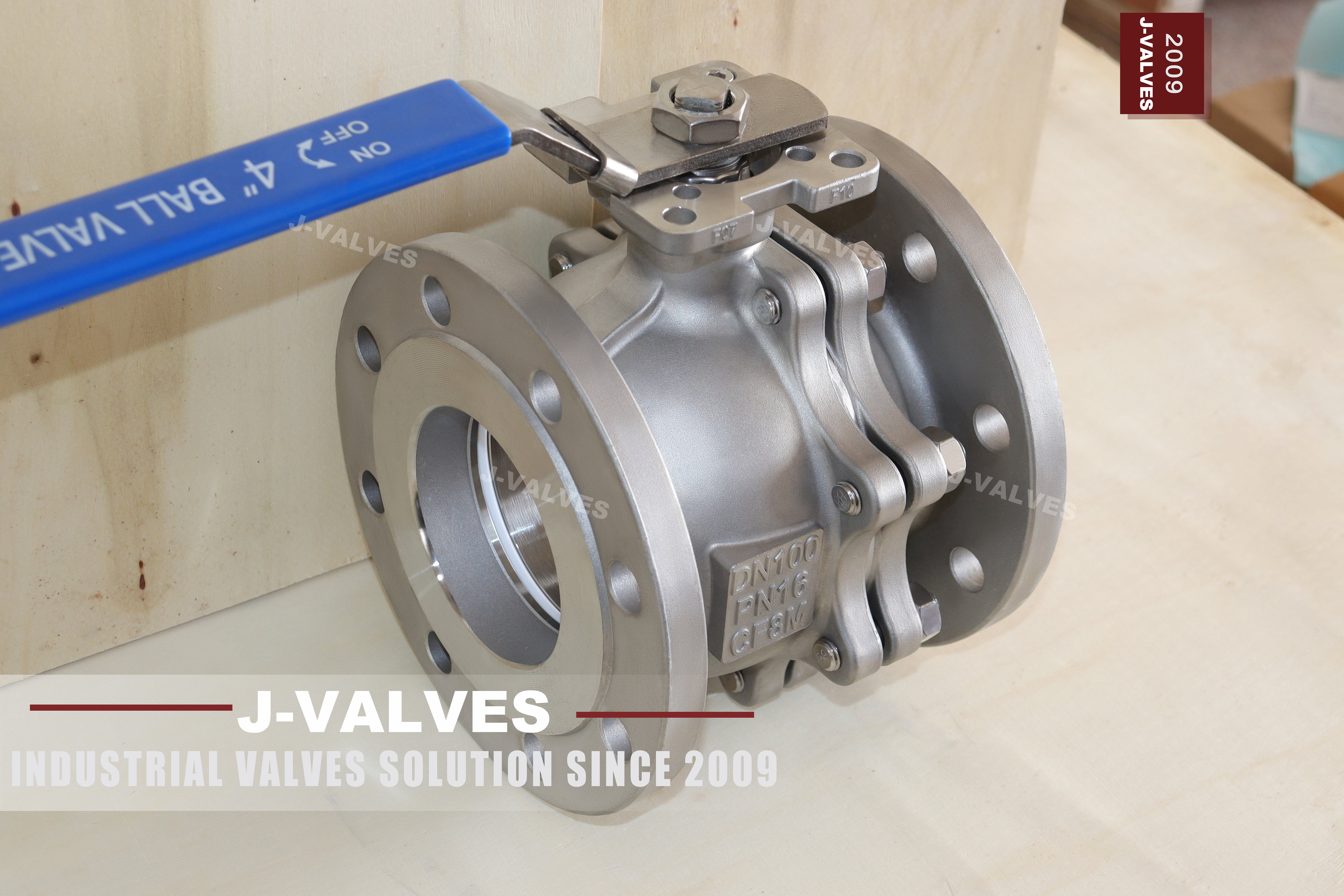
PN 40 and Class 300 are close enough in number to be confused and far enough apart in meaning that the confusion costs money. PN is a marking on a flange face, referenced to 20 Celsius, defined by a European standard. Class is a rating in a table, referenced to 38 Celsius, defined by an American one. Two different reference temperatures, two different tables, and two flanges that will not bolt together.
This page is a single size and a single marking: DN 25, PN 40, 316 stainless, floating ball, raised face. That narrowness is useful, because it lets the question be asked precisely. At DN 25 the PN 40 flange carries four bolts on an 85 millimetre bolt circle. The nearest American neighbour, one inch Class 150, also carries four bolts, on a 79.4 millimetre circle. Same count, different circle, and a joint that cannot be made.
The valve in the photographs is a stainless floating ball valve with a lever, a two or three piece body depending on the build, PTFE or reinforced PTFE seats, and a raised face flange to the European standard. It is the small bore isolation valve that fills utility and chemical lines in plants where the piping class is written to EN rather than to ASME.
The argument of this page is that the flange is a system, and a valve bought into one system cannot be evaluated with the numbers of another. A buyer who reads PN 40 as roughly Class 300 has made an assumption that is wrong in two separate ways: the reference temperature, and the geometry.
Design and Construction
The body is a floating ball design with a raised face flange at each end. The ball is not carried on trunnions; it rests between the two seats and is pushed into the downstream seat by the medium. At DN 25 that mechanism is comfortable, because the seat load is small and the torque is within what a lever applies.
The body construction can be two pieces or three depending on what is ordered, and the page does not distinguish them. That is not a trivial omission at this size, because a two piece body has one joint and one assembly path for the ball, and a three piece body has two joints and two. On a DN 25 valve the difference is small in cost and real in service: a three piece body can be opened without removing the end from the pipe in some installations, and a two piece cannot.
The seats are polymer, which is what sets the temperature line. 316 stainless would run well past 180 Celsius; PTFE and reinforced PTFE will not, and the printed range of minus 20 to plus 180 belongs to the seat rather than to the body. That is the same pattern as on every soft seated valve in this catalogue and it is worth repeating because it is the number most often read as a body property.
The stem is blowout proof, which at this size means a shoulder below the packing that is larger than the hole it passes through. It is a small feature and it is the difference between a gland that can be serviced live and one that cannot.

Material Options
The material list is short: 316 for the body, the ball and the stem, PTFE or reinforced PTFE for the seats. What the list does not say is that the flange is a different system from the body, and that the two have to be ordered together.
| Part | Material on This Build | What It Decides |
|---|---|---|
| Body | 316 stainless | Corrosion resistance and the wetted shell |
| Ball | 316 stainless, floating | The sealing band |
| Stem | 316 stainless, blowout proof | Torque and packing wear |
| Seats | PTFE or reinforced PTFE | The 180 Celsius ceiling |
| Body gasket | PTFE or spiral wound | The joint, on a multi piece body |
| Flange facing | Raised face form B1 | The gasket that can be used |
| Bolting | A2 or A4 stainless | Joint preload and corrosion |
The facing is a material decision in practice because it decides which gasket can be used. A raised face form B1 takes a flat gasket or a spiral wound one and seals over an area. A tongue and groove or a spigot and recess facing seals by confinement rather than by bolt load, and the gasket is a different part. Mixing facings between a valve and a mating flange is a joint that will not seal no matter how much torque is applied.
The bolting line matters on a stainless valve more than on a carbon one because of galvanic corrosion. Stainless bolting into a stainless flange is the ordinary choice; carbon steel bolting into a stainless flange is a corrosion cell at every stud, and the failure appears as a loose joint rather than as a cracked one.
Technical Specifications
The table keeps the page entries and adds the two geometric numbers that decide whether the valve can be installed, because the page does not print them.
| Item | Value |
|---|---|
| Size | DN 25, one inch nominal |
| Pressure marking | PN 40 to EN 1092-1 |
| Flange | EN 1092-1 type 21, raised face form B1 |
| Bolting on this flange | Four bolts on an 85 mm bolt circle |
| Nearest ASME neighbour | One inch Class 150, four bolts on 79.4 mm |
| Body | 316 stainless |
| Ball | 316 stainless, floating |
| Seats | PTFE or reinforced PTFE |
| Temperature | Minus 20 to plus 180 Celsius |
| Face to face | EN 558 for the DIN build |
| Design | ASME B16.34 for wall and material group |
| Test | API 598 or EN 12266-1 |
The face to face line is another place where two systems meet. A DIN build follows EN 558 for its length, and an ASME build follows B16.10. At DN 25 the two lengths are close but not the same, and a valve bought to the wrong one will not fit between flanges that were set for the other.
The design standard line is deliberately not a DIN standard. Wall thickness for a 316 body comes from the material group table in ASME B16.34, because that is where the table exists; the European system expresses the same requirement through the pressure equipment directive and the harmonised standards it points at. A valve can carry a PN marking and have its wall governed by an American table, and that is normal rather than contradictory.
Standards and Compliance
Three systems meet on this valve: the flange, the wall, and the test. They come from different documents and each one has to be satisfied on its own terms.
| Document | What it fixes | What It Does Not Fix |
|---|---|---|
| EN 1092-1 | Flange dimensions, drilling, facings, and the PN marking | The body wall of the valve |
| ASME B16.34 | Wall, material groups, class ratings | A PN marking |
| EN 558 | Face to face for the DIN build | An ASME build |
| ASME B16.5 | Flange dimensions and drilling for the ASME build | A PN marking |
| API 598 | Shell and seat test | A European PN rating |
| EN 12266-1 | Test procedures for industrial valves | An American class rating |
The PN marking is defined by the flange standard and it refers to a pressure at 20 Celsius. The class rating is defined by the American standard and its table rows are read at 38 Celsius. That difference of eighteen degrees is one of the reasons the two families are not convertible: the number on each is the pressure the material can take at a different reference temperature.
The geometry is the other reason, and at DN 25 it is the one that catches people. Both flanges carry four bolts, and the circles differ by several millimetres. A joint that is forced together on mismatched circles will bolt up if the holes are large enough, and it will leak because the gasket is not being compressed evenly.
A test certificate is the third system. A valve tested to API 598 produces a record in one form; a valve tested to EN 12266-1 produces one in another. Both are valid and they are not interchangeable on a project file, which is why the test standard belongs on the order even when the valve is the same.
Manufacturing Process
The body is cast or forged depending on the build, and the first machining operation establishes the bore axis and one flange face. The opposite face, the seat pockets and the stem bore are referenced to that axis, so a body that has been set up on a rough surface produces a valve whose seat is not square to its flanges.
The flange is drilled on a jig set for the European bolt circle. That jig is the physical difference between a DIN flange and one that merely looks like it: the outside diameter and the thickness can be close between systems, and the circle is what decides whether a bolt passes through. A shop that drills to the wrong jig produces a flange that is dimensionally plausible and useless.
The seat pocket is machined from the joint face and lapped or finished to suit the polymer seat. At this size the pocket is small and the finish is what matters: a polymer seat conforms to a slightly rough pocket but cannot correct one that is out of square, and an out of square pocket shows up as a seat that leaks on one side.
Assembly fits the seats and the ball, closes the body on its gasket, torques the studs in a crossing sequence, and fits the stem and packing. The lever goes on last, on a stem square cut after the gland face, so that the lever sits square to the gland rather than to the casting.

Quality Control and Testing
The shell test is applied with the ball open at the multiple of the rating that the test standard names, and the body joint is watched. On a two piece or three piece body the joint is the boundary that a one piece body does not have, and it is the first place a test leak appears. Written that way, a DN 25 PN 40 valve stops being a number and becomes a joint: a 316 body with a named seat, a raised face flange on an 85 millimetre circle, a length to a named standard, and a test record in the form the project will accept.
The flange is checked for bolt circle, bolt size, facing and thickness, against the standard the order named. That check is the one that prevents the most expensive kind of return, because a valve with the wrong drilling is not repairable and not usable, and it is discovered on site rather than at the works.
The plate carries the size, the PN, the grade and the heat number. On a DN 25 valve the plate is small and the temptation is to leave the heat number off; the heat number is the only line that ties the valve to a certificate, and a plate without it is a valve with no history.

Applications and Industry Service
Utility and plant water lines in European specification plants are the ordinary duty. The valve is small, the pressure is modest, and the requirement is isolation with a lever. In that service the EN flange is not a preference, it is the system the piping was built in. Written that way, a DN 25 PN 40 valve stops being a number and becomes a joint: a 316 body with a named seat, a raised face flange on an 85 millimetre circle, a length to a named standard, and a test record in the form the project will accept.
Marine and offshore service uses the EN system on the European built packages and the ASME system on the American ones, sometimes on the same vessel. That is where the flange question becomes practical: two spools that look alike and will not mate, and a store that has to keep both. Written that way, a DN 25 PN 40 valve stops being a number and becomes a joint: a 316 body with a named seat, a raised face flange on an 85 millimetre circle, a length to a named standard, and a test record in the form the project will accept.

Installation, Operation and Maintenance
Installation is a flange joint at each end, with the faces parallel before the bolts are tightened, and with a gasket suited to the facing. A raised face form B1 takes a flat or spiral wound gasket; using a ring joint ring in a raised face is a joint that will not seal and a gasket that will be destroyed.
The bolts are tightened in a crossing pattern to a torque the gasket asks for rather than to a feel. A DN 25 joint has four bolts and it is easy to overtighten one and leave another loose, which produces a joint that leaks on the loose side and crushes the gasket on the tight one. Written that way, a DN 25 PN 40 valve stops being a number and becomes a joint: a 316 body with a named seat, a raised face flange on an 85 millimetre circle, a length to a named standard, and a test record in the form the project will accept.
Maintenance is the packing from the top and the seats through the body joint. On a three piece body the internals can be reached with the valve in place in some installations; on a two piece body the end has to come off the pipe. At this size the practical policy is to keep a spare and swap it rather than to rebuild in place.
How to Specify and Order
The lines below are the ones a PN number does not carry, and the second one is the line that decides whether the valve fits the pipe.
| Line on the order | What to write | Why it matters |
|---|---|---|
| Size and PN | DN 25, PN 40, with the facing | PN alone does not define the joint |
| Flange standard and drilling | EN 1092-1, and the bolt circle if in doubt | The ASME one inch circle is different |
| Body construction | Two piece or three piece | It changes the maintenance path |
| Seat material | PTFE or reinforced PTFE | It sets the 180 Celsius ceiling |
| Face to face | EN 558 for the DIN build | B16.10 gives a different length |
| Test standard | API 598 or EN 12266-1 | The certificate has to match the project |
Written that way, a DN 25 PN 40 valve stops being a number and becomes a joint: a 316 body with a named seat, a raised face flange on an 85 millimetre circle, a length to a named standard, and a test record in the form the project will accept.
FAQ
Q: Is PN 40 the same as Class 300?
A: No, and they are not even read at the same temperature. PN 40 is a flange marking referenced to 20 Celsius; Class 300 is a rating whose table row is read at 38 Celsius and gives a higher pressure for the same material. The two numbers look close on a datasheet and are two different statements.
Q: Will a PN 40 valve bolt to a Class 300 flange at one inch?
A: Not at DN 25, where the two are most often confused, because the bolt circles differ and the flange diameters differ with them. At larger sizes the mismatch gets worse rather than better, and in every case the joint that is forced together is a joint that will not hold a test.
Q: Both have four bolts, so does it fit?
A: Bolt count is the least useful number to compare. Two flanges can carry the same number of bolts on circles several millimetres apart, which is exactly enough to look right and not enough to pass a bolt through. Measure the circle and the bolt size, not the count.
Q: What sets the wall thickness, PN or the design standard?
A: The design standard. Wall comes from the material group table in ASME B16.34, and PN is a marking on the flange face that says which pipe class the ends belong to. A valve can carry a PN marking and still have its wall governed by a table in a different document.
Q: Why does the temperature stop at 180 here when the body is 316?
A: Because the seat is the part in contact with the ball. PTFE and reinforced PTFE are comfortable to about that figure in continuous duty, and the 316 body would happily run hotter. The number on the plate is the valve, and the valve is limited by its softest part.
Hot Products


News
Direct Air Capture Ball Valves The Vacuum Side Runs The Seal Backwards, And Three Hundred Thousand Strokes Decide The Design
A solid sorbent DAC plant moves 1.3 million cubic metres of air per tonne of CO2, then asks a DN50 ball valve to hold 0.9 bar from the wrong side.
Read More
Your Ball Valve Is Not A Test Blind: What A Hydrotest Does To The Seats
A line test puts pressure on the wrong side of the seat logic, above the valve's own seat test, with water that stays in the pocket. What to arrange instead.
Read More
Remanufactured Ball Valves: Five Checks That Decide Whether A Rebuild Deserves A Certificate
A rebuild at 45 percent of price with half the life is no saving. Five checks that separate a real remanufacture from a repaint with a certificate.
Read More
The Squeeze Is A Residual: How Tolerance Stack-Up Decides Whether A Ball Valve Seals
No dimension sets the seat squeeze. Five tolerances do, in series. Why identical valves feel different, and why a new ball changes the arithmetic.
Read More