


CHINA J-VALVES Offers Various High-quality I ndustrial Ball Valves
J-VALVES, a distinguished professional ball valve manufacturer rooted in China, takes pride in its extensive product portfolio. Our offerings span a wide range, including trunnion-mounted ball valves, floating ball valves, high-temperature ball valves, high-pressure ball valves, metal-sealed ball valves, ultra-low temperature ball valves, DBB ball valves, Three-way And Four-way Ball Valve, and fully welded ball valves. Each product is a testament to our commitment to precision engineering and reliable performance. Meticulously crafted, they are designed to not only meet but exceed the most stringent industrial demands, ensuring stable operation even under extreme conditions. This enables us to provide our clients with high-value services and makes our valves widely sought-after in industries.
Product Category
Contact Us


-
J-VALVES-Q41F
-
J-VALVES
Overview of the J-VALVES three inch Class 150 CF8M floating ball valve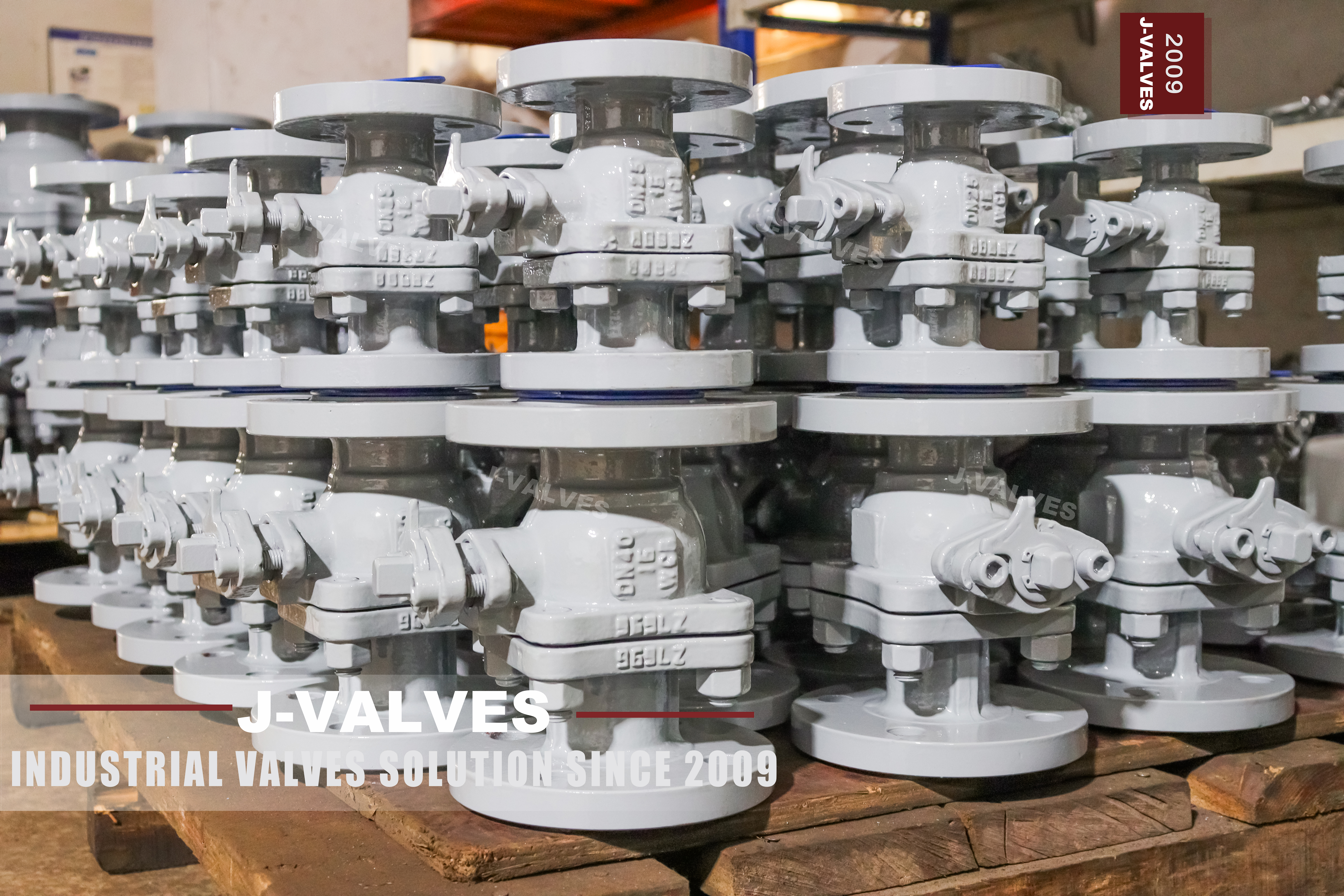
The heading on this page names one valve: three inch, Class 150, CF8M, floating ball. The parameter table underneath it names something else: a quarter inch to twelve inch, Class 150 to Class 2500. Both statements are on the same page, and a buyer who reads only one of them will order the wrong thing.
The heading is right about the valve in the photographs. It is a three inch, two piece, CF8M body with raised face flanges and a lever, and it is the size that gets stocked because it is the size most often asked for on a chemical or utility line. The table is right about the pattern: the same design is built from a quarter inch to twelve inch, and from Class 150 to Class 2500, and each of those builds is a different casting with a different wall.
Read together, the two statements say something useful, which is that the page is a pattern page wearing a size in its title. The size tells you what was photographed and what is on the shelf. The table tells you what can be quoted. Neither tells you what the valve can do at temperature, because that is decided by the seat.
The valve is a floating ball design: the ball is not carried on trunnions, it rests between two seats and is pushed into the downstream seat by the medium. That single fact explains the sealing behaviour, the torque curve, the reason a seat test is run twice, and the reason the pattern has an upper size limit at all.
Design and Construction
The body is two pieces, joined at one gasketed face and closed by a ring of studs. The ball and both seats go in through that joint, which is why there is a joint: a two piece body needs one opening large enough to pass the ball, and the end piece that closes it also carries one of the two flanges and one of the two seat pockets.
The ball sits between the two seats without any support other than the seats themselves. Line pressure on the upstream side pushes the whole ball downstream, so the downstream seat is loaded by the medium and the upstream seat is held against the ball by its own preload and the spring behind it. That is the mechanism, and it is worth stating precisely because the phrase floats freely suggests the opposite.
The stem is not a trunnion. It turns the ball and is sealed by packing, and it carries no radial load beyond what the seat friction puts on it. A blowout proof stem has a shoulder below the packing that is larger than the hole it passes through, so the stem cannot be ejected by pressure if the gland is dismantled with the line live.
The seat arrangement is what sets the temperature line. PTFE and reinforced PTFE are the only seats offered here, and both are polymers, so the ceiling is a polymer ceiling rather than a body ceiling. The CF8M body would run far above the seat limit, and that is exactly the kind of mismatch that produces a valve specified for a temperature it cannot hold.

Material Options
CF8M is a cast austenitic stainless to ASTM A351, equivalent in composition to 316, with molybdenum for chloride resistance. It is the standard choice for a cast body in chemical and utility service, and the page's material list is short because the pattern is offered in one grade rather than a family of them.
| Part | Material on This Build | What It Decides |
|---|---|---|
| Body and end piece | CF8M cast stainless to ASTM A351 | Corrosion resistance of the wetted shell |
| Ball | 316 stainless, turned and lapped | The sealing band and the bore |
| Stem | 316 stainless, blowout proof | Torque and packing wear |
| Seats | PTFE or reinforced PTFE | The temperature and pressure ceiling |
| Body gasket | Spiral wound or PTFE sheet | The single joint |
| Studs and nuts | A4 stainless | Joint preload and corrosion |
| Lever | Ductile iron or stainless, as ordered | The torque a hand can apply |
The ball row deserves a note because the page writes CF8M there as well. CF8M is a casting designation, and a ball is not cast: it is turned from bar or from a forging, ground, and lapped. The correct name for the ball is 316 or F316, and a casting grade in the ball row usually means the row was copied down from the body row without being changed. It is harmless on a quotation and confusing on a mill certificate.
The seat is the part that decides the service. PTFE is the standard, reinforced PTFE carries a filler for lower creep under load, and both are limited by the same mechanism: at temperature the polymer loses its ability to recover, and a seat that does not recover does not follow the ball. The 180 Celsius line on this page is that limit, and it is a limit on the seat rather than on the stainless.
Technical Specifications
The table below separates the two sets of numbers the page contains, because they answer different questions and a quotation usually needs only one of them.
| Item | Value |
|---|---|
| Size the heading names | Three inch, DN 80 |
| Size range in the table | Quarter inch to 12 inch, DN 15 to DN 300 |
| Class the heading names | Class 150, PN 20 |
| Class range in the table | Class 150 to Class 2500, PN 20 to PN 420 |
| Body | CF8M cast stainless, two pieces |
| Ball | 316 stainless, floating |
| Seats | PTFE or reinforced PTFE |
| Temperature | Minus 20 to plus 180 Celsius |
| Ends | Raised face flange to ASME B16.5 |
| Face to face | ASME B16.10 |
| Design | ASME B16.34 and API 608 |
| Test | API 598 and ISO 5208 |
The class range is the line that needs the most care, because 150 and 2500 on one page invite the reading that they are the same valve at two pressures. They are not. Wall thickness comes from the material group table in ASME B16.34, and the wall at 2500 for a given bore is several times the wall at 150. The seats, the stem diameter, the bolting and the flange all change with it, so the two ends of that column are different castings and different drawings.
The size range needs the same care for a different reason. A quarter inch floating valve is unremarkable; a twelve inch one is not built, because a floating ball seals by being pushed into its seat and the force available grows with the area of the bore while the parts that have to resist it grow only with the diameter.
Standards and Compliance
The two documents named on the page cover different things, and the boundary between them is where a specification usually goes wrong.
| Document | What it fixes | What it does not fix |
|---|---|---|
| ASME B16.34 | Wall, material groups, class ratings | Seat material or leakage |
| API 608 | Steel ball valves, DN 15 to DN 600, Class 150 to Class 600 | Anything above Class 600 |
| ASME B16.5 | Flange dimensions and drilling | The valve internals |
| ASME B16.10 | Face to face for flanged valves | Weld end or threaded lengths |
| API 598 | Shell and seat test procedure and acceptance | The seat the valve should have |
| API 607 | Fire test for quarter turn valves | A leakage rate in normal service |
API 608 covers this valve comfortably: three inch is inside DN 15 to DN 600, and Class 150 is inside Class 150 to Class 600. That is why the page can name it, and why the pages in this family that go to 2500 have to name API 6D instead. A document's scope is not a detail; it is the first thing a quotation should be checked against.
The fire test is a type test on a design and a size, and it says that a valve of this construction passed a test under defined conditions. It does not say the unit in the crate was tested, and it does not say the valve is fire proof. What it says is that after the soft parts are destroyed, the metal parts still restrict the flow to the rate the test allows.
The anti static requirement is worth one line because it is a real requirement in this pattern rather than a marketing line. A ball turning in polymer seats can accumulate charge, and a spring between the stem and the body gives the charge a path to earth. On a valve in a flammable service that spring is a safety device, not an accessory.
Manufacturing Process
The body halves are castings, and the first operation after fettling establishes the bore axis and one flange face. Everything else is referenced to that axis: the opposite flange face, the seat pocket, the stem bore and the body joint face. A casting that has been set up on a rough surface will produce a valve whose seat is not square to its flanges, and the error shows up as a seat that leaks on one side only.
The seat pocket is bored from the joint face side, in the same setting as the joint face itself where the machine allows it. Pocket depth, squareness and finish all matter, and the finish matters more on a polymer seat than on a metal one, because the polymer conforms to a rough surface but cannot correct a pocket that is out of square. Written that way, the page stops being a size and a table and becomes a valve: a three inch CF8M two piece body with one joint, a floating ball on polymer seats, raised face flanges to a named standard, and a temperature window that belongs to the seat the order names.
Assembly fits the seats and the ball through the joint, closes the end piece on its gasket, torques the studs in a crossing sequence, and fits the stem and packing from the top. The lever goes on last, on a stem square that has been cut after the packing gland face so that the lever sits square to the gland rather than to the raw casting.

Quality Control and Testing
The shell test is applied with the ball open at the multiple of the class that the test standard names, and the body joint is watched during it because it is the boundary that a one piece body does not have. A joint that weeps under the shell test is a gasket, a face or a torque sequence problem, and all three are cheaper to fix at the works than on site.
The seat test is run twice, once from each side, because a floating ball loads only its downstream seat. With pressure on one side, the upstream seat is held by preload alone, so a test from one side tells you about one seat. The procedure exists in that form because the mechanism requires it, not because the standard is being fussy.
The plate is struck after the tests, and it carries the size, the class, the grade and the heat number. The heat number is the only line on the plate that will never appear on a quotation, and it is the only line that lets a certificate be matched to a valve years later. Written that way, the page stops being a size and a table and becomes a valve: a three inch CF8M two piece body with one joint, a floating ball on polymer seats, raised face flanges to a named standard, and a temperature window that belongs to the seat the order names.

Applications and Industry Service
Chemical and petrochemical transfer is the largest single use, and it is the reason CF8M is the grade on the page. The molybdenum in the alloy gives it resistance to chlorides that 304 does not have, and most of the service that damages a stainless ball valve in a chemical plant involves chlorides at some concentration.
Water and utilities are the second family, and there the stainless grade is often chosen for the wetted path rather than for the pressure. A three inch valve on a plant water header at Class 150 is a valve that could have been carbon steel; it is stainless because the line is stainless and because a mixed material joint in a water system is a corrosion cell waiting to happen.
Food, beverage and pharmaceutical service uses the same pattern with a polished bore and a seat chosen for the cleaning regime. The requirement there is usually cleanability rather than pressure, and a floating ball with a full bore and a smooth pocket is easier to clean than a trunnion valve with cavities behind the seats.
Where the valve should not be used is on a line that needs throttling, on a line above the seat temperature, and on a line where the pressure class exceeds what a floating ball can hold at that size. A ball valve at part open puts the flow across the seat edge and erodes the polymer, and no grade of stainless changes that.

Installation, Operation and Maintenance
Installation is a flange joint at each end, with the valve supported so that the pipe does not hang from the body, and with the flange faces parallel before the bolts are tightened. A valve pulled into alignment by its bolts puts a bending load through the body joint, and that joint is the one that will weep first. Written that way, the page stops being a size and a table and becomes a valve: a three inch CF8M two piece body with one joint, a floating ball on polymer seats, raised face flanges to a named standard, and a temperature window that belongs to the seat the order names.
Maintenance reaches the packing from the top and the seats through the body joint. The joint gasket is renewed whenever the body is opened, and the seats are replaced as a pair rather than one at a time, because a new seat against a worn one loads unevenly. Written that way, the page stops being a size and a table and becomes a valve: a three inch CF8M two piece body with one joint, a floating ball on polymer seats, raised face flanges to a named standard, and a temperature window that belongs to the seat the order names.
How to Specify and Order
The lines below are the ones the heading and the table together do not settle, and the first one is the line that decides whether the valve can do the job.
| Line on the order | What to write | Why it matters |
|---|---|---|
| Size and class | For example three inch, Class 150 | The heading and the table disagree until this is written |
| Bore | Full or reduced | It changes the ball, the body length and the torque |
| Seat material | PTFE or reinforced PTFE | It sets the 180 Celsius ceiling |
| Temperature | Minimum and maximum in service | A seat limit is not a body limit |
| End standard | ASME B16.5, with the facing | The drilling has to match the pipe |
| Operator | Lever, gear, or actuator with a pad | The bracket follows from the pad |
Written that way, the page stops being a size and a table and becomes a valve: a three inch CF8M two piece body with one joint, a floating ball on polymer seats, raised face flanges to a named standard, and a temperature window that belongs to the seat the order names.
FAQ
Q: Why does the heading say three inch when the table says twelve?
A: Because the two lines answer different questions. The heading names the valve that was photographed and is stocked: three inch, Class 150, CF8M. The table describes what the same pattern is built in. Both are true, and a buyer who orders from the heading gets a valve while a buyer who orders from the table gets a range and still has to name a size.
Q: Is a twelve inch floating valve real?
A: Not in this pattern. A floating ball seals by being pushed into the downstream seat, so the seat load grows with the area of the bore while the stem and the seat ring grow only with the diameter. Somewhere above eight inch the torque and the seat distortion stop being manageable, and the same duty moves to a trunnion valve with a supported ball.
Q: The ball row says CF8M. Is the ball cast?
A: No. CF8M is a casting designation, and a ball is turned and lapped from bar or from a forging, so the correct name for it is 316 or F316. A casting grade in the ball row of a data sheet usually means the row was copied from the body row without being changed, which is harmless here and misleading on a certificate.
Q: Are Class 150 and Class 2500 the same valve at different pressures?
A: They share a pattern, not a body. Wall thickness comes from the material group table in ASME B16.34, and the wall at 2500 is several times the wall at 150 for the same bore. The seats, the stem diameter and the bolting change with it, so the two are different castings and different drawings.
Q: What sets the minus 20 to plus 180 range?
A: The polymer. CF8M keeps its properties far outside that window, but PTFE and reinforced PTFE are what touch the ball, and 180 is where a continuous duty polymer seat stops being a safe choice. Above that the valve needs a different seat, and the temperature line moves with it.


Hot Products


News
Direct Air Capture Ball Valves The Vacuum Side Runs The Seal Backwards, And Three Hundred Thousand Strokes Decide The Design
A solid sorbent DAC plant moves 1.3 million cubic metres of air per tonne of CO2, then asks a DN50 ball valve to hold 0.9 bar from the wrong side.
Read More
Your Ball Valve Is Not A Test Blind: What A Hydrotest Does To The Seats
A line test puts pressure on the wrong side of the seat logic, above the valve's own seat test, with water that stays in the pocket. What to arrange instead.
Read More
Remanufactured Ball Valves: Five Checks That Decide Whether A Rebuild Deserves A Certificate
A rebuild at 45 percent of price with half the life is no saving. Five checks that separate a real remanufacture from a repaint with a certificate.
Read More
The Squeeze Is A Residual: How Tolerance Stack-Up Decides Whether A Ball Valve Seals
No dimension sets the seat squeeze. Five tolerances do, in series. Why identical valves feel different, and why a new ball changes the arithmetic.
Read More