


CHINA J-VALVES Offers Various High-quality I ndustrial Ball Valves
J-VALVES, a distinguished professional ball valve manufacturer rooted in China, takes pride in its extensive product portfolio. Our offerings span a wide range, including trunnion-mounted ball valves, floating ball valves, high-temperature ball valves, high-pressure ball valves, metal-sealed ball valves, ultra-low temperature ball valves, DBB ball valves, Three-way And Four-way Ball Valve, and fully welded ball valves. Each product is a testament to our commitment to precision engineering and reliable performance. Meticulously crafted, they are designed to not only meet but exceed the most stringent industrial demands, ensuring stable operation even under extreme conditions. This enables us to provide our clients with high-value services and makes our valves widely sought-after in industries.
Product Category
Contact Us

-
J-VALVES-Q11F
-
J-VALVES
Overview of the J-VALVES three piece female screwed floating 316 stainless steel ball valve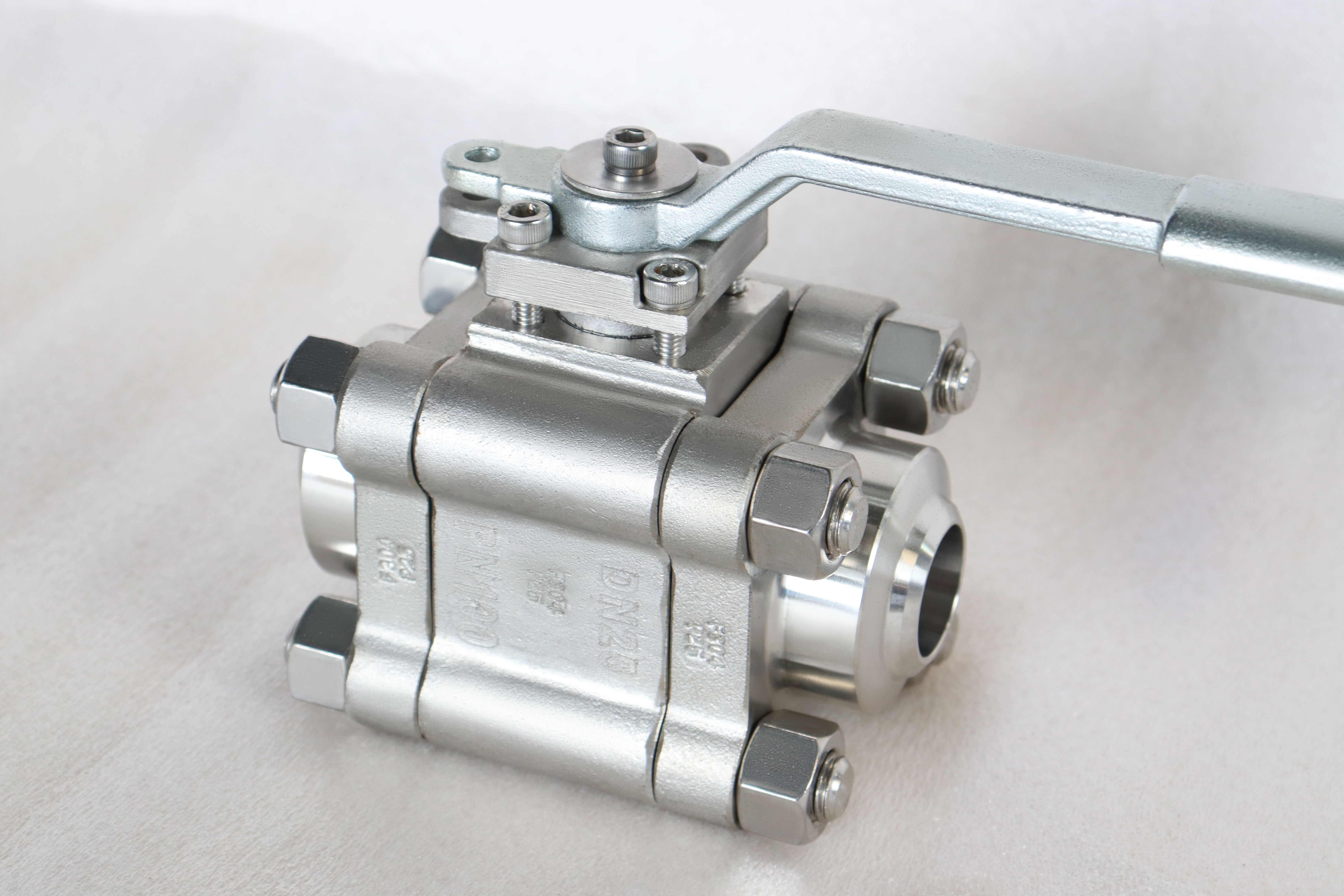
A connection line that reads ASME B1.20.1, BS 21 and ISO 228 has told the reader three things and decided nothing. Those are three thread systems, they do not interchange, and a valve that is offered with all three is a valve whose joint is chosen by whoever fills in the order.
The three are not variations on one theme. ASME B1.20.1 defines NPT: a taper thread with a 60 degree flank, sealing in the thread by wedging. BS 21 is the British taper form, 55 degree flank, and it seals the same way in a thread that is cut at a different angle. ISO 228 is the British parallel form, 55 degree flank, and it seals against a face or a washer, with the thread doing nothing but holding the joint together.
The difference that catches people is that the two families share a thread count at the small sizes. At half inch, NPT and BSP both run fourteen threads to the inch, so the first turn feels correct and the fitter keeps going. The flank angles are 60 and 55 degrees, so the threads interfere rather than mate, and the joint either binds before it seals or seals badly and then leaks.
The valve in the photographs is a three piece 316 screwed floating valve with a lever, a blowout proof stem, polymer seats and a body rated at 1000 PSI on the page. It is the small bore manual isolation valve that appears on dosing packages, instrument air headers, sample points and small chemical lines. Written that way, the valve stops being a body with three thread options and becomes a joint: a 316 three piece body with a named seat, two female threads cut and gauged to one named standard, a seal that is either in the thread or on a face, and a rating described for what it is.
Design and Construction
The body is three pieces: a centre piece carrying the ball and seats, and two end pieces that carry the female threads and close the seat pockets. The ball goes in from the centre, and each end piece holds one seat against it. That is why the layout is three pieces rather than two: both seat pockets are cut from the two end faces, so they are concentric by setup.
The end piece is the part that carries the thread, and that has a practical consequence: a damaged thread takes the end piece out of service and leaves the centre piece, the ball and the seats untouched. On a screwed valve that is the most common damage, because threads are damaged by cross threading and by over tightening far more often than seats are damaged by the medium.
The stem is not a trunnion. It turns the ball and is sealed by packing, and a blowout proof stem has a shoulder below the packing that is larger than the hole it passes through. At this size the shoulder is small and it is the difference between a gland that can be serviced and one that cannot. Written that way, the valve stops being a body with three thread options and becomes a joint: a 316 three piece body with a named seat, two female threads cut and gauged to one named standard, a seal that is either in the thread or on a face, and a rating described for what it is.

Material Options
The material list is short: 316 for the body, ball and stem, PTFE or reinforced PTFE for the seats. The decision that the list does not show is the thread, and on this valve the thread is the part that most often decides whether the installation works.
| Part | Material on This Build | What It Decides |
|---|---|---|
| Body and end pieces | 316 stainless, three pieces | Corrosion resistance of the wetted path |
| Ball | 316 stainless, floating | The sealing band |
| Stem | 316 stainless, blowout proof | Torque and packing wear |
| Seats | PTFE or reinforced PTFE | The temperature ceiling |
| Body gaskets | PTFE or spiral wound | The two joints |
| Thread | NPT, BSPT or BSPP, to one named standard | The joint and its seal location |
| Lever | Stainless or coated steel | The torque a hand can apply |
The thread line is the one that needs a note. NPT and BSPT are both taper threads and both seal in the thread, with a sealant filling the spiral gap. BSPP is parallel and seals on a face or a washer, with the thread only holding the joint together. That means the same nominal size can have its sealing surface in two completely different places, and a valve bought with the wrong one cannot be made to work with more tape.
The packing and the seat are both polymers and both are limited by temperature, but only the seat is in the flow path. A valve that is hot on the outside and cold in the bore will lose its seat before it loses its packing, which is why the seat line is the one to check first.
Technical Specifications
The table keeps the page entries and puts the thread line into three separate rows, because one row with three values is not a specification.
| Item | Value |
|---|---|
| Size range | Quarter inch to 4 inch, DN 6 to DN 100 |
| Pressure rating | 1000 PSI, a maker figure rather than a class |
| For comparison | Class 600 is 102.1 bar at 38 Celsius |
| Body | 316 stainless, three pieces |
| Ball | 316 stainless, floating |
| Seats | PTFE or reinforced PTFE |
| Temperature printed | Minus 20 to plus 425 Celsius |
| Temperature on a polymer seat | Minus 20 to plus 200 Celsius |
| Thread, American | NPT to ASME B1.20.1, 60 degree taper |
| Thread, British taper | BS 21, 55 degree taper |
| Thread, British parallel | ISO 228, 55 degree parallel |
| Seal location | In the thread for the tapers, on a face for the parallel |
| Design | ASME B16.34 |
| Test | API 598 |
The pressure line needs the comparison in the second row because 1000 PSI is a maker figure and a class is a table value. Class 600 for a 316 body is 102.1 bar at 38 Celsius, from the material group table, and it is a pressure with a temperature attached and a wall behind it. 1000 PSI is a cold working figure with no temperature and no wall statement, and the two should not be put on one line.
The temperature lines are the same pattern as everywhere else on soft seated valves: the printed range is a body figure, and the seat figure is roughly half of it. A valve ordered for a hot line needs the seat changed or the duty changed, and no amount of reading the pressure figure will resolve that.
Standards and Compliance
Three thread standards, one valve standard and one test standard appear here, and the three thread standards are the ones that decide whether the valve can be installed.
| Document | What it fixes | What It Does Not Fix |
|---|---|---|
| ASME B1.20.1 | NPT thread form, taper, gauging | A pressure rating for the joint |
| BS 21 | British taper thread form and gauging | Which sealant or torque to use |
| ISO 228 | British parallel thread form and gauging | A seal without a face or washer |
| ASME B16.34 | Wall, material groups, class ratings | The thread on the end |
| API 598 | Shell and seat test | A 1000 PSI rating |
| API 607 | Fire test for quarter turn valves | A normal service leakage rate |
The point that all three thread standards share is that none of them assigns a pressure rating. A thread is a form and a gauge; the pressure a joint can hold depends on the pipe, the wall, the sealant and the make up. A valve sold as 1000 PSI with threaded ends has a body rating and a joint whose limit is set somewhere else, and the lower of the two is the one that matters.
The 1000 PSI figure also has no home in a class table. API 598 tests to a multiple of whatever rating the valve is built to, and the class table that would give that rating does not have a 1000 psi row. That is not a reason to reject the valve; it is a reason to describe it as a maker rating rather than as a class.
The anti static spring is a real requirement on this pattern rather than a marketing line. A ball turning in polymer seats accumulates charge, and the spring gives the charge a path from the ball and stem to the body. On a valve in a flammable service that spring is a safety device.
Manufacturing Process
The end pieces are machined from bar or from a small forging, and the thread is cut after the gasket face is machined. That order matters: a thread cut before the face, or on a piece that has been turned over, pulls the joint into a bind when the valve is made up to a pipe, and the leak that follows is always blamed on the tape.
The thread itself is cut or rolled to the standard on the order, and it is checked with a gauge for that standard. There is no gauge that covers two systems, which is why a shop that offers three has to set up three times and cannot substitute one for another.
The seat pocket is bored from the joint face in the same setting as the face where the machine allows, so that the pocket is square to the joint and concentric with the thread. A pocket that is out of square produces a seat that leaks on one side only, and the symptom is often mistaken for a damaged seat.
Assembly fits the seats and the ball, closes the two joints on their gaskets, torques the studs in a crossing sequence, and fits the stem and packing. The lever goes on a stem square cut after the gland face, so it sits square to the gland rather than to the bar.

Quality Control and Testing
The thread is checked with a plug or ring gauge for the standard that was ordered, and the check is recorded. A thread that gauges correctly for NPT and is fitted to a BSPP port is a correct part in the wrong place, and the gauge record is what separates a manufacturing fault from an installation one.
The shell test is applied with the ball open at the multiple of the rating the standard names, with the ends plugged rather than flanged. A screwed valve needs a different rig from a flanged one, and the plugs have to be the right thread, which brings the thread question into the test bay as well. Written that way, the valve stops being a body with three thread options and becomes a joint: a 316 three piece body with a named seat, two female threads cut and gauged to one named standard, a seal that is either in the thread or on a face, and a rating described for what it is.
The plate carries the size, the rating, the grade and the heat number, and on a screwed valve it also carries the thread standard on some builds. Where it does not, the thread exists only on the order and in the gauge record, and a valve in a store with no paperwork has a thread that nobody can identify without a gauge.

Applications and Industry Service
Dosing and chemical packages are the ordinary duty. A quarter inch to one inch stainless screwed valve with a lever is the isolation point on a metering pump discharge, a sample line or a small transfer. The medium decides the body grade and the thread decides whether the package can be assembled.
Instrument air and utility headers are the second family, and there the pressure is modest and the requirement is a reliable joint. On those lines a parallel thread with a face seal is often preferred because it can be remade without disturbing the pipe. Written that way, the valve stops being a body with three thread options and becomes a joint: a 316 three piece body with a named seat, two female threads cut and gauged to one named standard, a seal that is either in the thread or on a face, and a rating described for what it is.
Where this valve should not be used is above four inch, above the seat temperature, and on any line that needs a joint with a defined pressure rating. The first is a make up torque limit, the second is a seat limit, and the third is a property that no thread standard provides.

Installation, Operation and Maintenance
Installation is a threaded joint at each end, made up to the standard the order named, with a sealant suited to the medium. A taper thread seals in the thread and needs a sealant; a parallel thread seals on a face and needs the face and washer to be right. Mixing the two produces a joint that either will not seal or will not come apart.
The body is supported so that the pipe does not hang from the threads, and the valve is not used as a union. A screwed valve that is unscrewed to break a line will have its threads damaged by the operation, and the damage takes the end piece out of service. Written that way, the valve stops being a body with three thread options and becomes a joint: a 316 three piece body with a named seat, two female threads cut and gauged to one named standard, a seal that is either in the thread or on a face, and a rating described for what it is.
Maintenance reaches the packing from the top and the seats through the joints. A damaged thread is repaired by replacing the end piece rather than by chasing the thread, because a chased thread is a thread that no longer gauges, and a joint that does not gauge is a joint that will leak.
How to Specify and Order
The lines below are the ones the connection line does not settle, and the first one is the line that the page leaves open.
| Line on the order | What to write | Why it matters |
|---|---|---|
| Thread standard | NPT, BS 21, or ISO 228, and only one | The three do not interchange |
| Thread size and gender | For example half inch female | The size alone does not define the joint |
| Seal type | In the thread, or on a face | Taper and parallel seal in different places |
| Size and bore | For example one inch, full bore | It changes the body and the torque |
| Seat material | PTFE or reinforced PTFE | It sets the 200 Celsius ceiling |
| Pressure basis | 1000 PSI maker rating, or a class | They are different kinds of number |
Written that way, the valve stops being a body with three thread options and becomes a joint: a 316 three piece body with a named seat, two female threads cut and gauged to one named standard, a seal that is either in the thread or on a face, and a rating described for what it is.
FAQ
Q: Why does one valve list three thread standards?
A: Because the line is an option list rather than a description of one valve. A quarter inch body can be threaded to any of the three, and the works will cut whichever is on the order. A page that lists three without asking for a choice has described the workshop rather than the product.
Q: Will an NPT male thread seal into a BSPP female port?
A: No. At half inch both run fourteen threads to the inch, so the first turn feels right, but the flank angles differ and the parallel form seals on a face while the taper seals in the thread. The joint binds, and forcing it damages both parts.
Q: What is BS 21 and how does it differ from ISO 228?
A: BS 21 is the British taper thread, the same 55 degree form the Japanese and European standards call BSPT, and it seals by wedging in the thread. ISO 228 is the parallel form, BSPP, which seals against a face or a washer and relies on the thread only to hold the joint together.
Q: Why is 425 Celsius printed when the seat is PTFE?
A: Because 425 is a body figure. The 316 body can run there, and the polymer seat cannot; the seat sees the ball and the ball sees the medium. The number that decides whether the valve survives is the one on the seat, and this page carries both lines so the difference is visible.
Q: Where does the threaded range stop and flanging begin?
A: Around four inch. Beyond that the make up torque on a taper thread is more than a fitter can apply evenly, the pipe has to be supported on both sides of the valve, and the joint becomes the weak point of the run. Larger sizes are flanged because the joint, not the body, is what fails.
Hot Products


News
Direct Air Capture Ball Valves The Vacuum Side Runs The Seal Backwards, And Three Hundred Thousand Strokes Decide The Design
A solid sorbent DAC plant moves 1.3 million cubic metres of air per tonne of CO2, then asks a DN50 ball valve to hold 0.9 bar from the wrong side.
Read More
Your Ball Valve Is Not A Test Blind: What A Hydrotest Does To The Seats
A line test puts pressure on the wrong side of the seat logic, above the valve's own seat test, with water that stays in the pocket. What to arrange instead.
Read More
Remanufactured Ball Valves: Five Checks That Decide Whether A Rebuild Deserves A Certificate
A rebuild at 45 percent of price with half the life is no saving. Five checks that separate a real remanufacture from a repaint with a certificate.
Read More
The Squeeze Is A Residual: How Tolerance Stack-Up Decides Whether A Ball Valve Seals
No dimension sets the seat squeeze. Five tolerances do, in series. Why identical valves feel different, and why a new ball changes the arithmetic.
Read More