CHINA J-VALVES Offers Various High-quality I ndustrial Ball Valves
J-VALVES, a distinguished professional ball valve manufacturer rooted in China, takes pride in its extensive product portfolio. Our offerings span a wide range, including trunnion-mounted ball valves, floating ball valves, high-temperature ball valves, high-pressure ball valves, metal-sealed ball valves, ultra-low temperature ball valves, DBB ball valves, Three-way And Four-way Ball Valve, and fully welded ball valves. Each product is a testament to our commitment to precision engineering and reliable performance. Meticulously crafted, they are designed to not only meet but exceed the most stringent industrial demands, ensuring stable operation even under extreme conditions. This enables us to provide our clients with high-value services and makes our valves widely sought-after in industries.
Product Category
Contact Us


-
J-VALVES-Q47F
-
J-VALVES
Overview of the J-VALVES forged trunnion mounted ball valve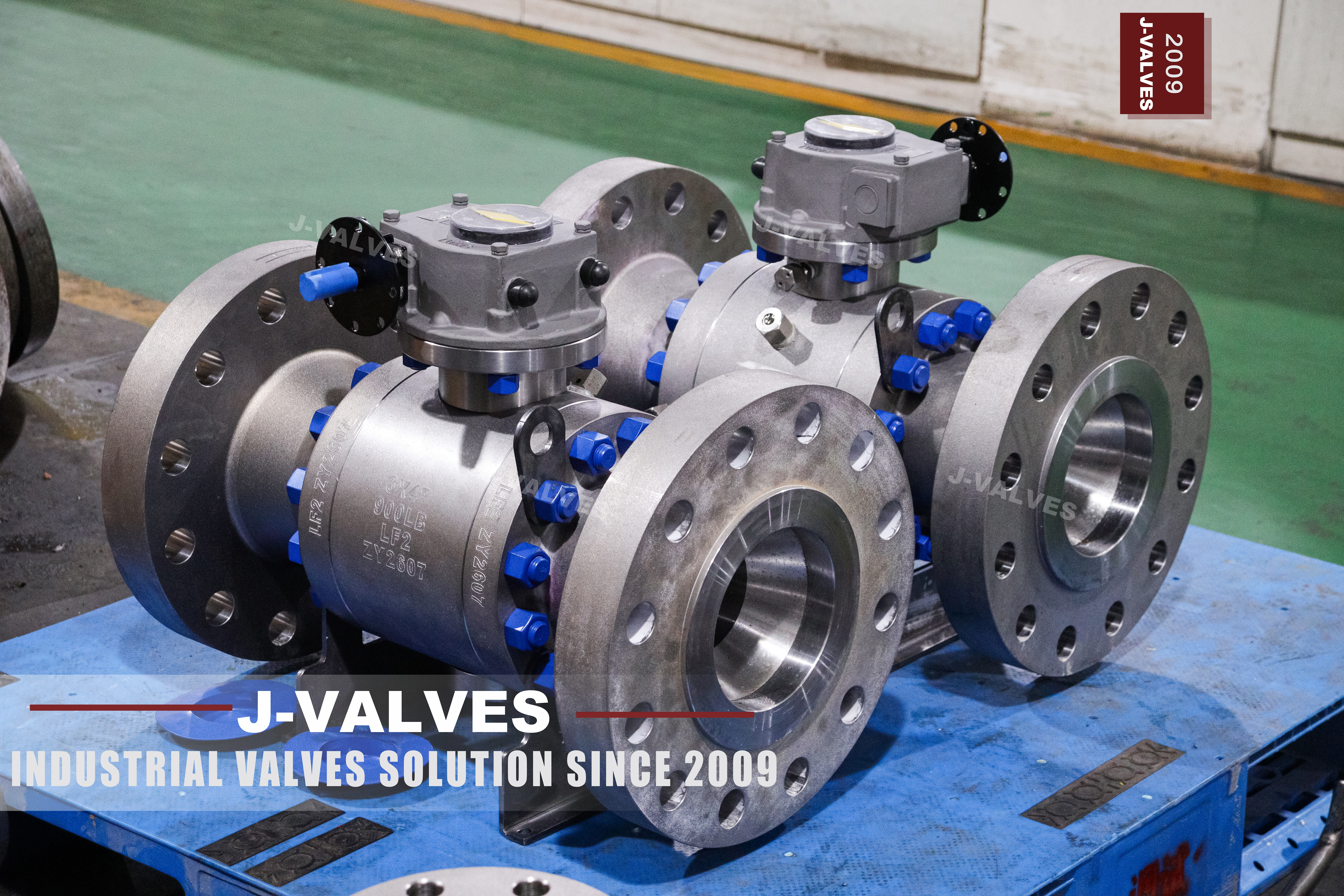
The photograph on this page shows a four by three inch Class 900 forged body with no handle on it. The stem comes out of the body as a machined shaft, standing above a square pad with four stud holes, and there is a small bracket beside it with an arm on it. Nothing turns the valve, and that is not because the picture was taken before the operator was fitted.
A valve shipped like this is sold as an actuator ready body, and the pad is the interface everything else is built around. It follows ISO 5211, which fixes the bolt circle, the number of holes and the drive form for a given pad size, so an actuator can be selected against the pad rather than against the valve maker's model number. The arm beside the stem is a travel stop that the actuator or the lever will register against.
The argument of this page is that the operator interface is part of the valve specification and not an accessory bought later. Three things have to be right before an actuator can be mounted: the pad size, the stem drive and the torque the valve actually needs. The first two are on the drawing, the third is on a test sheet, and a valve bought without that third number is a valve whose actuator is chosen by guesswork.
Design and Construction
The body is a three piece forged design: a centre section holding the ball and both seats, and two end pieces bolted to it, with a ring of studs at each joint. The ball is trunnion mounted, so the pressure load goes into bearings at the top and bottom of the ball rather than into the seats, and the seats only have to seal.
The pad is a machined square face on top of the bonnet with four tapped holes, and the four holes are on a bolt circle that belongs to a standard size. An actuator with a matching pad pattern bolts straight on with four studs and needs nothing else; an actuator with a different pattern needs an adapter plate, and an adapter plate is a stack tolerance between the actuator output and the stem that has to be shimmed.
The drive is the part that transmits the torque, and on this size it is a square or a keyed shaft. A square drive is symmetrical and can be indexed in four positions; a keyed shaft has one position and puts the torque into a single key. Both are standard, and an actuator is ordered with the matching output, which is why the drive form has to be written on the valve order rather than measured when the actuator arrives.
The travel stop is the bracket and arm beside the stem. On a bare stem valve the stop is what prevents the ball from being turned past its open or closed position by hand, and on an actuated valve the same stop provides the mechanical limit that the actuator's own end of travel setting works against. A valve supplied without a stop relies on the actuator alone, and an actuator set up against a stem with no stop can drive the ball onto the back of the seat.

Material Options
The body and the end pieces are A105N forged carbon steel, and the stamp on the body reads four by three, nine hundred, A105N, with the same grade stamped on the end pieces beside their heat numbers. The trim on this build is stainless, and the seat is the part that sets the temperature.
| Part | Material on This Build | Note |
|---|---|---|
| Centre section | A105N forged, normalised | Stamped with size, class and grade |
| End pieces | A105N forged | Stamped separately, own heat |
| Ball | Stainless, hardened | Trunnion mounted, not floating |
| Stem | Stainless, keyed or square drive | Carries the whole operating torque |
| Seats | Reinforced PTFE, polyimide, or metal | Sets the temperature limit |
| Body joint gaskets | Spiral wound | Two joints on a three piece body |
| Studs and nuts | B7 with a coating, or B8M | B7M where hardness is capped |
| Actuator mounting | ISO 5211 pad, four studs | The interface on this page |
The stem is the trim part that matters most on an actuator ready valve. It is both a pressure boundary and a torque member, and it passes through the packing, so it is the one part that is loaded, sealed and driven at the same time. A stem that is adequate for a lever can be marginal for an actuator that delivers the same torque faster, because the torque is the same and the rate of application is not.
The A105N grade on this body is a heat treatment record as much as a material. Normalising after forging refines the grain and gives a toughness that the as forged condition does not have, and the certificate that proves it is a heat treatment record rather than a chemistry sheet. On a Class 900 carbon steel body that record is worth asking for by name.
Technical Specifications
| Item | Value |
|---|---|
| Size | Four inch by three inch, DN 100 by DN 80 |
| Pressure class | Class 900, PN 150 in the API 6D table |
| Rating at 38 Celsius | 153.2 bar, ASME B16.34 group 1.1 |
| Body | A105N forged, three piece, two joints |
| Bore | Reduced, three inch through a four inch body |
| Flange | Four inch Class 900, eight bolt holes |
| Face to face | ASME B16.10 for four inch Class 900 |
| Temperature | Minus 29 to plus 425 Celsius, seat dependent |
| Stem | Bare, square or keyed, on an ISO 5211 pad |
| Travel stop | Bracket and arm at the stem |
| Design | API 6D, ASME B16.34 |
| Test | API 598 shell and seat, plus a torque record |
The 153.2 bar beside Class 900 is the ASME B16.34 tabulated rating for group 1.1 at 38 Celsius, and it is a number that repays being written down because the same class is often printed as 150 bar, which is a round conversion rather than the table. The rating falls as the temperature rises, so the class is a curve and the figure at 38 Celsius is only its first point.
The PN figure is 150 and it is not the same thing as 150 bar. Class 900 is PN 150 in the API 6D designation list, and a page that reads PN 150 as a pressure in bar has understated the class by a factor of about six. That confusion is common enough on catalogue pages that it is worth stating plainly: the PN number in that list is a designation, not a pressure.
Standards and Compliance
| Requirement | Document | What It Means Here |
|---|---|---|
| Product requirements | API 6D | Design, materials, marking, testing |
| Wall and rating | ASME B16.34 | Class 900 for the group set by A105 |
| Flanges | ASME B16.5 | Eight bolt holes at four inch Class 900 |
| Actuator interface | ISO 5211 | Pad size, bolt circle, drive form |
| Pressure test | API 598 | Shell at 1.5 times, seat at 1.1 times |
| Fire test | API 607 or ISO 10497 | Type test against a stated scope |
| Material certificate | EN 10204 3.1 | Heat number per pressure part |
ISO 5211 is the document that makes a bare stem valve a practical purchase. Without it, every actuator would need an adapter made for the valve it was going on, and the pad on the valve would be a machining detail rather than a stated interface. With it, the pad has a designation, the designation has dimensions, and the actuator can be ordered in parallel with the valve.
API 608 does not appear in that table and its absence is deliberate. API 608 runs from DN 15 to DN 600 in Class 150 to Class 600, and this article is Class 900, so the only product standard that covers it is API 6D. A quotation that offers a Class 900 small bore valve to API 608 has offered a document that does not reach the article.
Manufacturing Process
Each of the three pieces is forged, normalised, and then machined. Class 900 at four inch is a thick walled body, and the forging route is what allows the wall to be examined by ultrasonic testing before the bore is finished, when the section is still simple enough for a probe to cover.
The stem bore is machined in the same setting as the pad face and the four stud holes, so that the drive is square to the pad and the actuator sits flat. A pad machined in a second setting gives an actuator that rocks on the pad and a drive that binds at one part of the quarter turn, and neither of those is visible until the actuator is on.
The seat pockets are cut from the two faces of the centre section on one setting, and the two end pieces are identical. On a reduced bore body the ball is smaller than the end opening, so the ball can be inserted from either end, which is what makes the two end pieces interchangeable rather than handed.

Quality Control and Testing
| Step | Check | Acceptance |
|---|---|---|
| 1 Incoming | Heat number against the mill certificate | Chemistry and mechanicals |
| 2 Examination | Ultrasonic or magnetic particle to the order | Acceptance level stated |
| 3 Normalising | Heat treatment record for A105N | Recorded by heat |
| 4 Machining | Pad face, stud holes and stem bore in one setting | Drawing |
| 5 Shell test | Body and both joints at 1.5 times | API 598, no leakage |
| 6 Seat test | Each seat at 1.1 times, both directions | API 598 rate |
| 7 Torque | Breakaway and running torque recorded | Feeds the actuator selection |
| 8 Final | Stem protected, bores capped, crated | Works standard |
The torque row is the one that turns the bare stem from a problem into an advantage. Because no operator is fitted, the valve can be measured on its own at the works, and the figures that come back describe this valve rather than a family. Breakaway torque and running torque are two different numbers and an actuator has to be sized on the first while its air consumption follows the second.
The seat test is run in both directions on a trunnion valve because each seat seals against pressure from one side. That is a difference from a floating valve, where the ball moves to the downstream seat and only one seat is loaded at a time, and it is the reason a trunnion valve has two seat results per ball rather than one.

Applications and Industry Service
A bare stem Class 900 forged body belongs where the valve will be actuated from the start: emergency shutdown loops, remote operated isolation, wellhead and test lines, high pressure gas letdown, and the small bore high pressure branches of a process unit where the actuator is part of a safety function.
In those applications the valve is chosen for its pressure capability and its interface, and the actuator is chosen for its failure mode. A spring return actuator that closes on air failure and a double acting one that stays put are both correct for different duties, and the valve has to be able to accept either on the same pad pattern.
It is the wrong valve where the duty is manual isolation at a location nobody automates, because a bare stem valve needs a lever or a gearbox and both are cheaper bought with the valve. It is also the wrong valve where the actuator is to be mounted on site without a torque record, because the actuator will then be sized against a catalogue figure for the size and class.

Installation, Operation and Maintenance
The actuator is mounted with the valve in the position it will be operated, the stem is cleaned and lightly greased, and the actuator output is set to the stem drive before the four studs are tensioned. Mounting an actuator with the valve part open and then setting the travel through the actuator is how a ball gets driven onto the back of its seat, and the damage shows up as a leak that appears a month later.
After mounting, the travel stops are set from the valve rather than from the actuator. The valve's own stop defines closed, the actuator's limit switch is set to that position, and the open position is set the same way. A limit switch set to where the actuator thinks closed should be is a switch that reports closed on a valve that is not.
Operation is a quarter turn with an actuator that has enough torque at the pressure the line actually holds, and the margin between the valve's breakaway torque and the actuator's output is the number that decides whether the valve will still operate at the end of a year. That margin is a decision and it belongs in the specification rather than in the actuator supplier's catalogue.
How to Specify and Order
The six entries are size, class, body grade, seat, end connection and operator, and on this valve the operator entry is a pad and a drive rather than a handle. It has to name the pad size to ISO 5211, the drive form and size, and the travel stop arrangement, and those three lines are what let the actuator be ordered without waiting for the valve to arrive.
The second thing to write is the torque basis. Breakaway torque at the maximum differential pressure, recorded per valve, is the figure an actuator is sized on, and a valve ordered without that record leaves the actuator selection to a table. The cost of getting it wrong appears as a valve that strokes slowly at the top of the pressure range and then not at all.
Documents to name: the EN 10204 3.1 certificate for all three pieces, the normalising record for A105N, the ultrasonic or magnetic particle report with its acceptance level, the shell and seat test record with two seat results per ball, the torque record, and the general arrangement drawing with the pad size, the drive form and the stem projection above the pad.
FAQ
Q: Why does the valve arrive with no handle?
A: Because the operator is being bought separately, and the valve is built to accept either a lever, a gearbox or an actuator on the same pad. Shipping it bare lets the valve be measured on its own at the works, which is where the torque figure an actuator is sized on comes from.
Q: What does the four stud pad follow?
A: ISO 5211, which fixes the pad size, the bolt circle, the number of holes and the drive form. With that standard in place an actuator can be ordered against the pad rather than against the valve model, and the two can be bought in parallel.
Q: Why is the torque measured rather than taken from a table?
A: Because a catalogue figure covers a family of builds with different seats and trims, and the spread inside that family is wider than the margin an actuator is usually bought with. Breakaway torque and running torque are two different numbers, and the actuator is sized on the first.
Q: Is Class 900 covered by API 608?
A: No. API 608 runs from DN 15 to DN 600 in Class 150 to Class 600, so this article is outside it and API 6D is the only product standard that covers it. A quotation offering a Class 900 small bore valve to API 608 has offered a document that does not reach the article.
Q: What is the bracket beside the stem for?
A: It is the travel stop. On a bare stem valve it stops the ball being turned past open or closed by hand, and on an actuated valve it provides the mechanical limit that the actuator end of travel is set against. Without it the actuator alone defines where the ball stops.



Hot Products


News
Remanufactured Ball Valves: Five Checks That Decide Whether A Rebuild Deserves A Certificate
A rebuild at 45 percent of price with half the life is no saving. Five checks that separate a real remanufacture from a repaint with a certificate.
Read More
The Squeeze Is A Residual: How Tolerance Stack-Up Decides Whether A Ball Valve Seals
No dimension sets the seat squeeze. Five tolerances do, in series. Why identical valves feel different, and why a new ball changes the arithmetic.
Read More
Why A Ball Valve Gets Harder To Turn: Five Causes, And The Test That Tells Them Apart
A ball valve that stiffens over months points at one of five parts. Measure torque with the line pressurised and again vented, and the split becomes visible.
Read More
The Ball Valve at Four Thousand Bar: Seat Load, Erosion And Fatigue in Waterjet Circuits
At 4,000 bar a 10 mm bore puts 31 kN on the seat and a 0.1 mm leak cuts steel. What a ball valve must survive in a waterjet or intensifier circuit.
Read More