CHINA J-VALVES Offers Various High-quality I ndustrial Ball Valves
J-VALVES, a distinguished professional ball valve manufacturer rooted in China, takes pride in its extensive product portfolio. Our offerings span a wide range, including trunnion-mounted ball valves, floating ball valves, high-temperature ball valves, high-pressure ball valves, metal-sealed ball valves, ultra-low temperature ball valves, DBB ball valves, Three-way And Four-way Ball Valve, and fully welded ball valves. Each product is a testament to our commitment to precision engineering and reliable performance. Meticulously crafted, they are designed to not only meet but exceed the most stringent industrial demands, ensuring stable operation even under extreme conditions. This enables us to provide our clients with high-value services and makes our valves widely sought-after in industries.
Product Category
Contact Us


-
J-VALVES-Q347F
-
J-VALVES
Overview of the J-VALVES two piece cast steel trunnion valve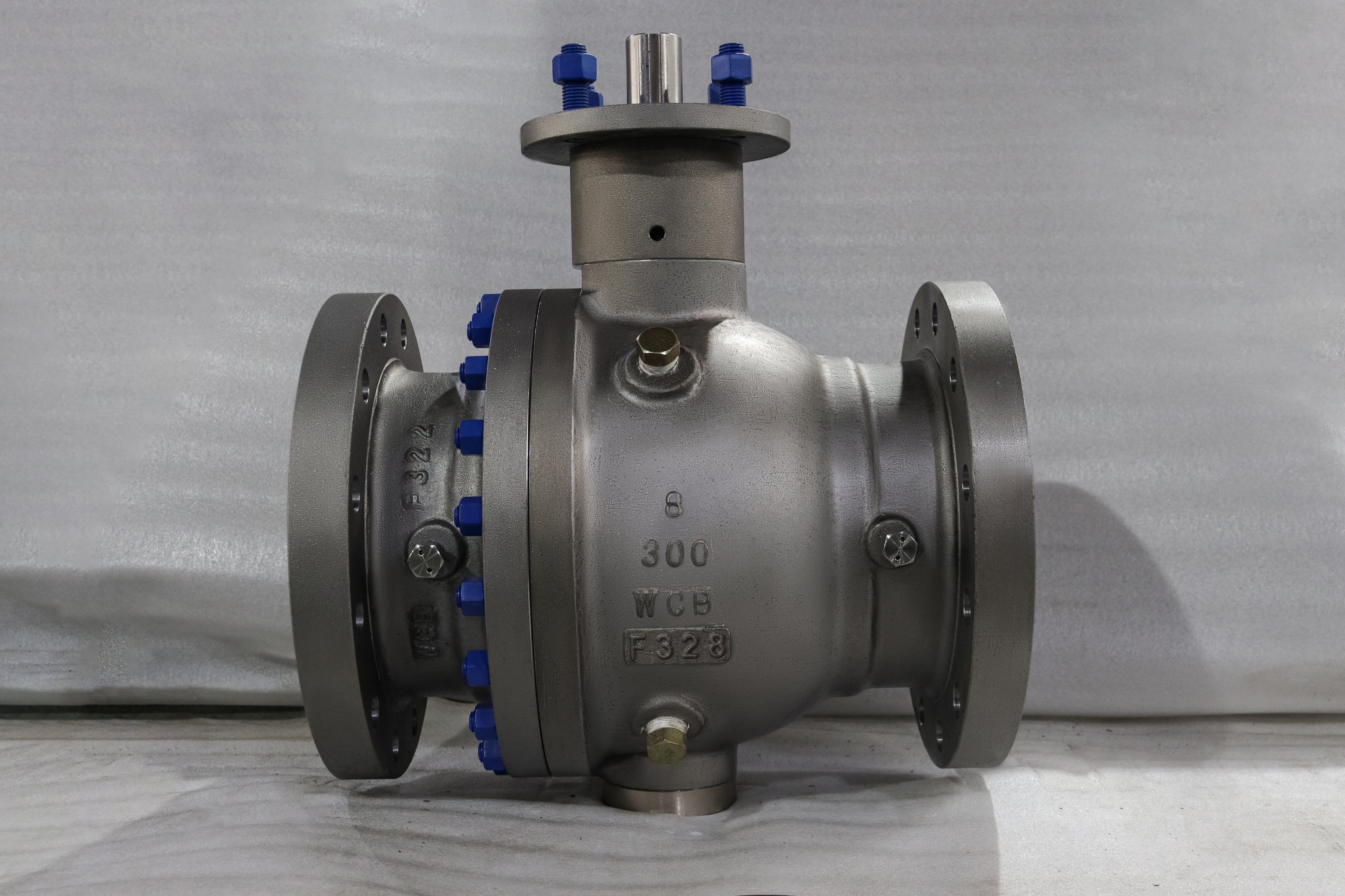
The photograph shows a sixteen inch Class 300 cast carbon steel body, and the first thing a fitter notices is that the handwheel is not on the valve. It is on a bracket, standing off to one side of the gearbox, at a height that a person can reach without a ladder. That bracket is not an accessory bolted on at the end of the build. It is a decision taken when the valve was ordered.
A sixteen inch Class 300 trunnion valve is a large article, and everything about handling it changes at that size. The operating torque is beyond a lever, so a gearbox is fitted; the gearbox input is at the top of a body that is already tall, so the wheel goes on a stand; and the body has no lifting lugs, so the rigging has to be planned around the shape rather than around a marked lifting point.
The argument of this page is that at this size the valve stops being a component and becomes part of the piping layout. The stand height, the wheel plane, the side the wheel faces and the space left for a sling are all decided with the pipe, and a valve ordered without them arrives as a correct valve that does not fit the platform it was bought for.
Design and Construction
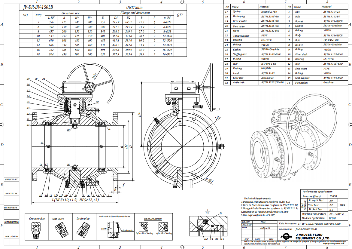
The body is a two piece cast trunnion design: a main body carrying the ball, the seats and the trunnion bearings, and one end piece closing the other side. A single ring of studs, visible round the body in the photograph, holds the joint. The ball is carried on an upper and a lower trunnion, so the pressure load goes into bearings and the seats only seal.
The gearbox sits on a machined pad at the top of the body and is driven by the valve stem. Its input shaft carries the handwheel on a bracket that also carries a bearing, and that bearing is the reason the stand exists in this form. Without it the wheel would hang on the gearbox input shaft alone, and the side load a person puts on a wheel that size would go straight into the input seal.
The stem between the body and the gearbox is an extension, and an extension is a shaft in torsion with two bearings rather than one. It has to be sized for the torque of the valve and stiff enough in torsion that the lost motion does not appear as backlash at the wheel, and it is the part of a stand build that is easiest to get wrong because it is invisible once assembled.
The joint between the two body pieces is a spigot and recess closed by studs, with a gasket between the faces. On a sixteen inch body the joint face area is large and the gasket is a spiral wound type, and the studs are tensioned in a cross pattern rather than worked around the circle. The joint is the only place on this body where the pressure boundary is fastened rather than cast.
The body in the photograph carries cast lettering on the barrel, reading sixteen, three hundred and WCB, with a fourth line that is the heat number. Those marks come from the pattern and the heat is put on after casting, and neither of them says anything about the bore, the trim or the operator, all of which are stated on the drawing and the nameplate.
Material Options
The body on this page is A216 WCB cast carbon steel, which is the standard choice at this size because a forging of this diameter is not a practical route. The trim is where the choices start, and on a large cast body the trim is also where most of the cost of a rebuild sits.
| Part | Material on This Build | Note |
|---|---|---|
| Body and end piece | A216 WCB cast carbon steel | One pattern for each piece |
| Ball | Carbon steel with a hard facing, or stainless | Wear surface, not pressure boundary |
| Stem | F6a, F304 or F316 | Takes the full operating torque |
| Seat | Reinforced PTFE, PPL, or metal | Sets the temperature limit |
| Body joint gasket | Spiral wound, stainless winding | One joint on a two piece body |
| Studs and nuts | B7 with a coating, or B8M | B7M where hardness is capped |
| Packing | PTFE or graphite | Graphite above the polymer limit |
The ball is the part that gets confused with the body on a carbon steel valve. WCB is a pressure boundary grade, and it is not a bearing surface, so the ball is either a different material or the same material with a facing applied to the sealing band. Either way the ball is a trim item, and its description belongs in the trim column of the order rather than in the body column.
The seat choice decides the temperature the valve can be sold for, and on a sixteen inch body the seat is also a large part with a large seating load. A polymer seat at this size and class is a wide ring under a load that grows with the bore, which is why large bodies tend towards a metal seat with a hard facing even where the medium would allow a polymer.
Technical Specifications
| Item | Value |
|---|---|
| Size | Sixteen inch, DN 400 |
| Pressure class | Class 300, PN 50 in the API 6D table |
| Body | A216 WCB cast carbon steel, two piece |
| Body joints | One, closed by a stud ring |
| Ends | Raised face or ring joint to ASME B16.5 |
| Face to face | ASME B16.10 for sixteen inch Class 300 |
| Temperature | Minus 29 to plus 425 Celsius, seat dependent |
| Operator | Gearbox on a stand with a handwheel |
| Wheel position | Set by the stand, stated on the drawing |
| Lifting points | None cast in, rigging per the drawing |
| Design | API 6D, ASME B16.34 |
| Test | API 598 shell and seat |
The PN figure beside Class 300 is 50, and it comes from the API 6D designation list rather than from a conversion. The list runs Class 150 as PN 20, Class 300 as PN 50, Class 600 as PN 100, Class 900 as PN 150, Class 1500 as PN 250 and Class 2500 as PN 420, and a page that prints PN 40 for Class 300 has converted a pressure in bar and rounded it downwards, which is an error in the direction that matters.
The absence of a lifting point in that table is deliberate and it is worth reading as a line item. There is no cast lug on this body, no tapped hole for an eye bolt, and no marked slinging position, so the rigging has to be worked out from the drawing and the mass on it. That is normal for a valve of this size and it is still the step where a body gets damaged on site.
Standards and Compliance
| Requirement | Document | What It Means Here |
|---|---|---|
| Product requirements | API 6D | Design, materials, welding, marking |
| Wall and rating | ASME B16.34 | Class 300 for the group set by WCB |
| Flanges | ASME B16.5 | Sixteen inch is inside the tabulated range |
| Casting quality | MSS SP-55 | Visual acceptance, level named on the order |
| Pressure test | API 598 | Shell at 1.5 times, seat at 1.1 times |
| Fire test | API 607 or ISO 10497 | Type test against a stated scope |
| Material certificate | EN 10204 3.1 | Heat number per pressure part |
Sixteen inch is inside the tabulated range of ASME B16.5, which runs to twenty four inch, so this body takes a standard flange. That stops being true above twenty four inch, and it stops again above Class 900 in the large flange standard, and both of those limits are worth knowing before a large valve is quoted with a flanged end.
MSS SP-55 is the standard nobody puts on the order and everybody argues about at the receiving dock. It defines visual acceptance for steel castings, and it has several levels, so an order that says the casting is to be sound has said nothing. Naming the level, and naming who inspects against it, converts a matter of opinion into a check.
Manufacturing Process
The body and the end piece are cast in sand, cleaned, stress relieved and then machined. The pattern fixes the shape of the outside and the lettering on the barrel, and the core fixes the bore and the seat pockets, so a change of bore on the same pattern is a change of core rather than a change of tooling.
Machining is done with the flange faces, the joint face and the trunnion bores referenced to one centreline. On a body this large the seat pockets are cut after the joint face, because the joint face is what the end piece registers against, and a pocket cut before that reference exists will be off centre by the amount the joint face was out.
The gearbox mounting pad is machined in the same setting as the stem bore, so that the gearbox input is square to the stem. A pad machined in a second setting puts the gearbox at an angle to the stem, and the symptom is a wheel that turns stiffly at one part of the quarter turn and freely at another.

Quality Control and Testing
| Step | Check | Acceptance |
|---|---|---|
| 1 Incoming | Heat number against the mill certificate | Chemistry and mechanicals |
| 2 Casting | Visual acceptance to MSS SP-55 | Level named on the order |
| 3 Machining | Joint face, seat pockets, stem bore, pad | One setting, drawing |
| 4 Joint fit | Gasket compression and stud tension | Drawing figure, cross pattern |
| 5 Shell test | Body and joint at 1.5 times | API 598, no leakage |
| 6 Seat test | Each seat at 1.1 times, both directions | API 598 rate |
| 7 Operator | Gearbox and stand assembled, stops set | Full quarter turn, no fouling |
| 8 Final | Faces protected, bores capped, crated | Works standard |
The operator row is not usually on a test sheet and it belongs there. A gearbox on a stand is assembled at the works, its stops are set there, and the assembly is proved by turning the valve through its quarter turn with the wheel. A stand that fouls the body at the open position, or a wheel that comes within a hand's width of a flange, is a problem that shows up in that check and nowhere else.

Applications and Industry Service
Sixteen inch Class 300 cast carbon steel is the workhorse size and class for a large bore block valve: water and utility headers, cooling water, product pipelines at moderate pressure, and the isolation points around a tank farm. In those services the valve spends its life fully open, is closed for maintenance, and is judged on whether it still seals after five years of that.
The gearbox and stand earn their place in that duty because the valve has to be operable by one person at the platform. A valve that needs a bar on the wheel, or two people, is a valve that will be left partly open. Getting the wheel to a workable height is not a refinement, it is the difference between a block valve and a valve that is nominally closed.
It is the wrong valve where the line is above a live road or a walkway with no platform, because the wheel then has to be reached from a ladder. In that case a chainwheel or an actuator is the answer, and both of them change the space the valve needs, which puts the decision back with the piping designer rather than with the valve supplier.

Installation, Operation and Maintenance
Lifting is by slings round the body barrel, on both sides of the joint so that the body does not rotate, with a spreader if the sling angle would crush the stand. The gearbox, the stand and the wheel are not lifting points and are not to be used as one, because a bent wheel or a distorted stand is a valve that will not turn properly for the rest of its life and cannot be straightened in the field.
The valve goes in with the pipe flanges parallel and supported, and the joint studs are tensioned after the pipe is aligned rather than while it is being pulled into line. On a body this size the pipe is stiff enough to hold the valve joint open at one side, and a joint closed against that load leaks at test pressure and looks correct at hand tight.
Operation is a quarter turn, fully open or fully closed. The gearbox is greased at the interval on its plate rather than by habit, the stops are checked once a year, and the wheel is left in the position the procedure says rather than wherever it was when the last person finished. A large valve left part open in a dirty line collects debris on the seat face, and that debris is the start of the leak nobody can find later.
How to Specify and Order
The six entries that define the article are size, class, body grade, seat, end connection and operator, and on this valve the operator entry is longer than the other five. It has to state the gearbox ratio class, the stand height, the side the wheel faces and whether the wheel is to be plain or chain operated, because each of those changes the envelope the pipe has to leave for it.
Two questions belong to the platform rather than to the valve. Where the operator will stand, and how the valve will be lifted into place. Neither of them appears on a valve data sheet, both of them decide whether the installation works, and both of them are cheaper to settle at the enquiry stage than after the valve has arrived.
Documents to name: the EN 10204 3.1 certificate with the heat number that is cast into the body, the MSS SP-55 acceptance level and the name of the inspector, the shell and seat test record, the operator assembly record showing the stops set and the quarter turn proved, and the general arrangement drawing with the face to face, the stand height, the wheel position and the lifting arrangement.
FAQ
Q: Why is the gearbox on a stand instead of on the valve?
A: Because the top of a sixteen inch body is already high, and a wheel mounted directly on the gearbox would be turned from a ladder. The stand puts the wheel at a working height and lets it stand clear of the body, and it carries its own bearing so the side load from the wheel does not reach the gearbox input seal.
Q: Does the stand change the torque?
A: It adds a stem extension in torsion between the body and the gearbox, with two bearings rather than one. The extension has to be sized for the valve torque and stiff enough that lost motion does not appear as backlash at the wheel, which is why a stand is a drawing item rather than a catalogue option.
Q: How is a body with no lifting lugs handled?
A: With slings round the barrel, on both sides of the joint so the body cannot rotate, and a spreader if the sling angle would load the stand. The gearbox, the stand and the wheel are not lifting points: a bent wheel is a valve that will not turn properly for the rest of its life.
Q: Can a sixteen inch valve be ordered with a chainwheel?
A: Yes, and it is the right answer where there is no platform at the wheel height. A chainwheel changes the envelope the valve needs and the chain run becomes a layout question for the piping designer, so the decision belongs with the layout rather than with the valve.
Q: Why does the body have no cast bore figure?
A: Because the stamp records size, class and grade, and the bore is not one of them. Full bore and reduced bore are both built on this pattern, so the bore comes from the model and the drawing rather than from the casting, and a replacement must be ordered on both numbers.



Hot Products


News
Remanufactured Ball Valves: Five Checks That Decide Whether A Rebuild Deserves A Certificate
A rebuild at 45 percent of price with half the life is no saving. Five checks that separate a real remanufacture from a repaint with a certificate.
Read More
The Squeeze Is A Residual: How Tolerance Stack-Up Decides Whether A Ball Valve Seals
No dimension sets the seat squeeze. Five tolerances do, in series. Why identical valves feel different, and why a new ball changes the arithmetic.
Read More
Why A Ball Valve Gets Harder To Turn: Five Causes, And The Test That Tells Them Apart
A ball valve that stiffens over months points at one of five parts. Measure torque with the line pressurised and again vented, and the split becomes visible.
Read More
The Ball Valve at Four Thousand Bar: Seat Load, Erosion And Fatigue in Waterjet Circuits
At 4,000 bar a 10 mm bore puts 31 kN on the seat and a 0.1 mm leak cuts steel. What a ball valve must survive in a waterjet or intensifier circuit.
Read More