


CHINA J-VALVES Offers Various High-quality I ndustrial Ball Valves
J-VALVES, a distinguished professional ball valve manufacturer rooted in China, takes pride in its extensive product portfolio. Our offerings span a wide range, including trunnion-mounted ball valves, floating ball valves, high-temperature ball valves, high-pressure ball valves, metal-sealed ball valves, ultra-low temperature ball valves, DBB ball valves, Three-way And Four-way Ball Valve, and fully welded ball valves. Each product is a testament to our commitment to precision engineering and reliable performance. Meticulously crafted, they are designed to not only meet but exceed the most stringent industrial demands, ensuring stable operation even under extreme conditions. This enables us to provide our clients with high-value services and makes our valves widely sought-after in industries.
Product Category
Contact Us

-
J-VALVES-Q347F
-
J-VALVES
Overview of the J-VALVES three piece forged steel flanged trunnion ball valve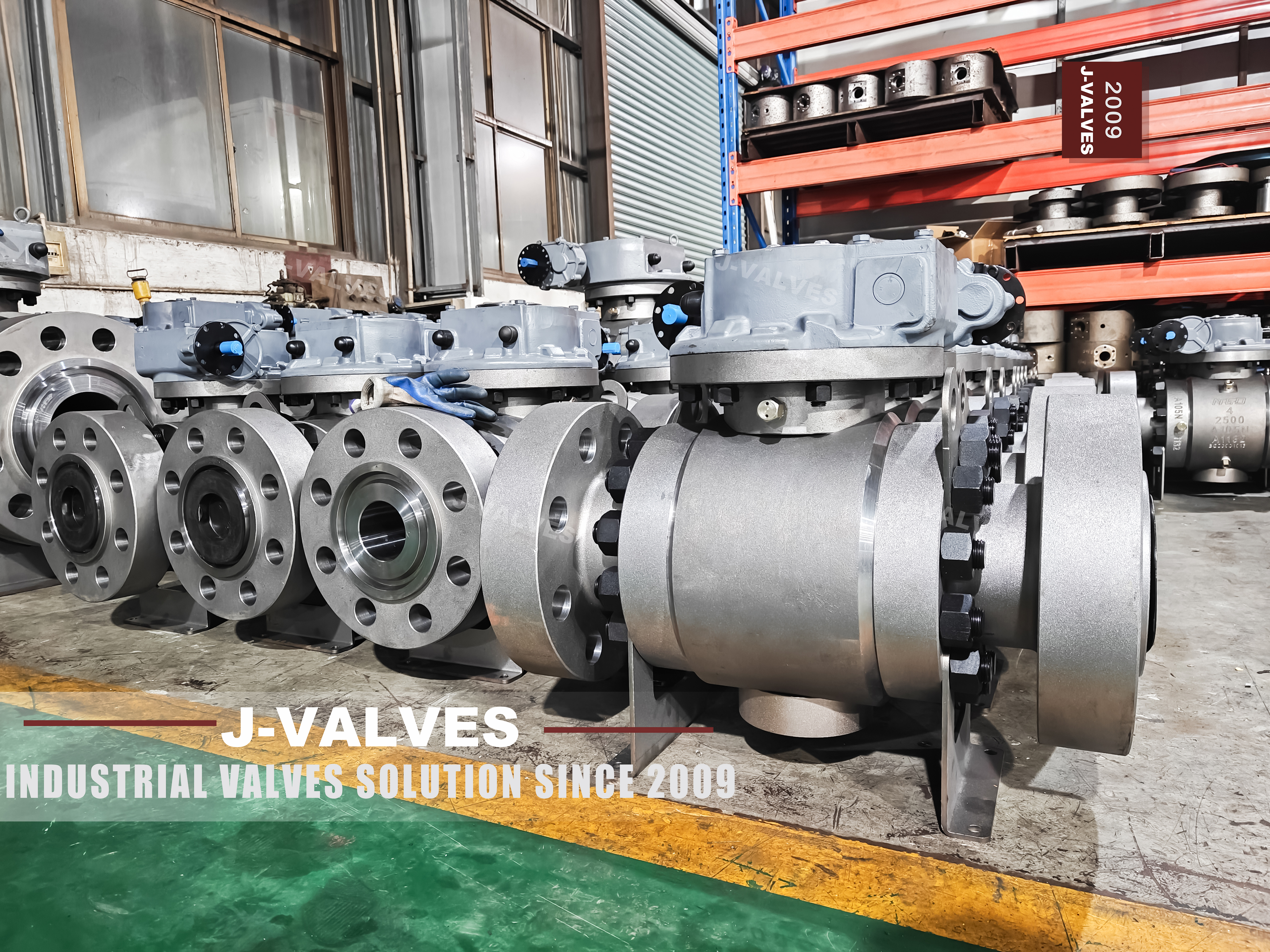
Two inch to sixty inch, Class 150 to Class 2500, raised face, ring joint or butt weld. Written as a line, that reads like a grid a buyer can pick from: any size, any class, any end. The grid has two edges that are not there. Above twenty four inch a flanged end exists only to Class 900, and above twenty four inch the face to face standard named on this page stops as well.
That is not a small print issue. A sixty inch valve at 2500 is a real requirement in gas transmission and it cannot be flanged, so it is welded, and its length comes from a different document. A buyer who reads the range line and orders a flanged sixty inch at high class has ordered something that no standard describes and no foundry can drill.
The rest of the page is competent: forged body, three pieces, trunnion ball, hardfaced or polymer seats, ends to the flange standards for the sizes where those standards reach. The work here is to draw the two edges and then read the valve inside them.
Design and Construction
The body is three pieces: two end caps and a main body carrying the ball and both seats, bolted at two joints. The page calls it a one piece forged valve body in the first paragraph and a three piece body in the second, which is one of the small contradictions a template produces. What is on the photographs and in the parts list is a three piece forged body, and the reason for the split is the same at every size: both seat pockets can be cut from one face of the centre section in one setting.
The ball is carried on trunnions and the seats are loaded by springs and then by line pressure. Because the shafts take the thrust, the torque stays within reach of a gearbox at sizes where a floating valve would be immovable, and the seats can be designed for sealing rather than for holding. That architecture is what makes a range that reaches sixty inch possible at all.
Ends are where the range stops being uniform. Raised face and ring joint to ASME B16.5 cover nominal sizes up to twenty four inch, and ring joint becomes the only facing at the top of the class range in the larger sizes. Butt weld ends to ASME B16.25 have no such ceiling, which is why they are the only practical option in the corner of the grid where the size and the class are both large.
The length dimension follows the ends rather than the valve. ASME B16.10 publishes face to face dimensions for flanged and weld end valves up to twenty four inch. Above that the lengths come from API 6D or from the manufacturer, and a page that names B16.10 for a range that reaches sixty inch is naming a document that stops at the size where the question starts to matter.
The two joints scale differently from the bore. A joint is a ring of studs of a given size on a given pitch, and the load it carries grows with the area it encloses, so the stud size and the number of studs climb faster than the diameter. At twenty four inch the joint is already a serious piece of bolting, and at sixty inch it is the part of the valve that decides how the valve is maintained: two large joints mean two gaskets, two torque sequences and two places to check after every thermal cycle.

Material Options
The body is offered in A105N, F304 or F304L, F316 or F316L. The carbon steel is the default for oil and gas at moderate temperature and the stainless grades are for corrosive service or for low temperature where a carbon steel body would lose toughness. All of them are forgings, which is the point of the range: a forged body has no casting porosity to find on a sealing surface, and it can be made in sizes where a casting would be a gamble.
| Part | Material on This Build | What It Decides |
|---|---|---|
| Body and end caps | A105N, F304 or F304L, F316 or F316L forged | Rating at temperature and corrosion resistance |
| Ball | F304 or F316 with hardfacing, or carbide coated | The sealing band and its wear life |
| Seat | F304 or F316 with hardfacing, or nickel alloy | The rubbing pair and the temperature ceiling |
| Stem | F316, 17-4PH, or a nickel alloy | Torque and packing wear |
| Sealing | Polymer at the low end, metal at the high end | Leakage rate and temperature |
| Packing | Flexible graphite with alloy wire reinforcement | The stem seal |
| Bolting | A193 B7, B8 or B8M with matching nuts | Joint preload and corrosion |
| Ends | Raised face or ring joint to B16.5, butt weld to B16.25 | The joint at the pipe, and the size ceiling |
| Operator pad | To ISO 5211 | Which operator can be fitted |
The stainless option is not a cosmetic upgrade at this size. A sixty inch forged body in F316 is a large forging with a long lead time, and the reason to buy it is a medium that would destroy carbon steel, not a preference for stainless. Where the line is carbon steel and the medium is dry gas, A105N is the correct answer and the stainless price is a penalty paid for nothing.
The ball and seat rows carry the same trade as everywhere in this family. A polymer seat gives a tight rate at moderate temperature; a metal pair gives temperature and wear resistance at a looser rate. On a range that reaches sixty inch, the seat choice is settled by the class and the medium long before it is settled by preference, because a large polymer seat at high class is a ring that will be extruded.
Technical Specifications
| Item | Value |
|---|---|
| Size range | Two inch to sixty inch, DN 50 to DN 1500 |
| Class range | Class 150 to Class 2500 |
| Body | A105N, F304 or F316 forged, three pieces |
| Ball | F304 or F316, trunnion mounted |
| Seat | Polymer or metal, by class and temperature |
| Ends, up to 24 inch | Raised face or ring joint to ASME B16.5, butt weld to B16.25 |
| Ends, above 24 inch | Butt weld to ASME B16.25, or hub ends |
| Length, up to 24 inch | ASME B16.10 |
| Length, above 24 inch | API 6D or the manufacturer drawing |
| Design | ASME B16.34 and API 6D |
| Test | API 598 and API 6D |
| Operation | Gear, or actuator on an ISO 5211 pad |
The class range on the page is written as 150 to 2500 with a bracket that reads PN 10 to PN 420, and the bottom of that bracket is wrong. Class 150 is PN 20 in the API 6D correspondence, and PN 10 has no class equivalent at all: it is a European flange marking with no row in the class table. A range that starts at PN 10 is describing a flange that the valve does not have.
The upper corner is the corner this page is about. At twenty six inch and above, a flanged end is covered by ASME B16.47, and that standard stops at Class 900. So a thirty six inch valve at 1500 or a sixty inch valve at 2500 has no flanged end in any standard: it is a welded valve, or it is a special design with a hub end, and the page's own end list already says so in a line that is easy to read past.
Standards and Compliance
| Document | What it fixes | What it does not fix |
|---|---|---|
| ASME B16.5 | Flanges up to 24 inch, all classes | Anything above 24 inch |
| ASME B16.47 | Flanges 26 to 60 inch, to Class 900 | Class 1500 and 2500 |
| ASME B16.25 | Butt weld ends | Flanged ends |
| ASME B16.10 | Face to face up to 24 inch | Lengths above 24 inch |
| ASME B16.34 | Wall, material groups, class ratings | Ends, lengths, seats |
| API 6D | Pipeline valves to 2500, test, marking, large sizes | Refinery practice |
| API 608 | Steel ball valves, DN 15 to DN 600, Class 150 to Class 600 | The upper part of this range |
Two documents on the page do not reach the range they are printed beside. API 608 stops at Class 600 and at DN 600, which is twenty four inch, so it covers the small end of this page and nothing else. ASME B16.10 stops at twenty four inch as well. Neither is wrong to name; both are wrong to name without a boundary, and the boundary is the same number in both cases.
The weld end is the document that carries the large sizes. ASME B16.25 defines the weld preparation, and the length for a weld end valve above twenty four inch comes from API 6D or from the drawing. A buyer replacing a large valve in an existing line needs the length and the weld preparation to match what is already there, and neither of those is answered by a range line.
Manufacturing Process
Forging a body for a large valve is a press problem before it is a machining problem. The centre section of a sixty inch valve is a heavy forging, and the shape has to be close enough to the finished part that the machining allowance is affordable. That is why the three piece architecture survives at this size: three manageable forgings are easier to make, heat treat and inspect than one large one, and each can be tested before it is assembled.
Machining the centre section establishes the seat pockets and the trunnion bores from one axis, and at large sizes the machine that can hold the part is the constraint rather than the tolerance. The pockets are bored and checked for squareness, the flange faces or weld preparations are cut, and the whole part is inspected before the end caps are offered to it, because a defect found at that stage is a rework and a defect found after assembly is a scrap.
Assembly at the large sizes is a lifting operation as much as a fitting operation. The ball is set into the centre section, the seats are fitted, the end caps are landed on their gaskets and the studs are torqued in a crossing sequence while the assembly is supported so that the weight of an end cap does not load one side of the joint. A large valve assembled on the ground without support can be square on the bench and out of square in the line.

Quality Control and Testing
The shell test is the event that proves the forging and the two joints, and at large sizes it is also a test of the test rig. The seat test is run from each side and read against a rate. Both are ambient tests, and both are recorded against the serial number so that the certificate and the plate can be matched later.
The dimensional check matters as much as the pressure test on this page, because the failure mode of a large valve is usually a fit rather than a leak. Flange drilling, facing, face to face length and the weld preparation are checked against the drawing, and the length is checked at the temperature of the shop rather than assumed. A large valve that arrives with the right pressure rating and the wrong length is a valve that will be cut and re welded in the field.

Applications and Industry Service
Gas transmission is the first use for the large sizes, and it is where the welded end is the normal answer. A sixty inch line at high class is welded because there is no flange for it, and the valve is installed as a spool piece with weld ends prepared to B16.25. The same line at a lower class can be flanged to B16.47, which is why the class range and the end form have to be read together.
Liquid lines, pump stations and storage terminals take the middle of the range, where flanged ends are available and the valve can be unbolted for maintenance. Oil and gas processing takes the stainless builds, where the medium is corrosive and the forged body is chosen for both the pressure and the cleanliness of the metal.
Where the valve should not be used is at the corner where the size and the class both sit at the top and the design has not been agreed. A sixty inch 2500 valve is a project, not a catalogue item: it needs a drawing, a weld procedure, a length agreed with the piping design, and a test plan. Treating it as a line in a range table is how projects end up with a valve that fits nothing.
Replacement work is the case where the range line misleads most. A valve going into an existing line has to match a length that was set by the original design, and above twenty four inch that length is not in B16.10. The old valve is measured, the drawing is made to that measurement, and the weld preparation is cut to B16.25 so the joint closes with the bevel that is already on the pipe. None of that is visible in a table that runs from two inch to sixty.

Installation, Operation and Maintenance
Installation at the flanged sizes is a joint at each end, with the faces parallel, the gaskets correct for the facing and the valve supported so that the pipe does not hang from the body. At the welded sizes the valve is aligned, tacked, welded to a procedure and inspected, and the valve is left open during welding so that heat does not distort a seat that is only a short distance from the arc.
Operation is a geared quarter turn at every size where a handwheel cannot supply the torque, and the gear ratio is chosen on the breakaway torque rather than on the running torque. A valve that has sat closed at pressure for a season needs its highest torque on the first degree of travel, and that is the number the gearbox has to be able to deliver.
Maintenance follows the ends. A flanged valve can be unbolted and taken out; a welded valve is cut out or repaired in place, which changes the economics of every decision about seats and spares. That is the practical reason the end form belongs on the first line of the order and not on the last.
How to Specify and Order
| Line on the order | What to write | Why it matters |
|---|---|---|
| Size and class | Both numbers, together | The top corner of the grid has no flanged end |
| End form | Flanged to B16.5 or B16.47, or butt weld to B16.25 | The standard changes with the size |
| Length | The dimension and the document it comes from | B16.10 stops at twenty four inch |
| Body grade | A105N, F304 or F316, with the certificate | The stainless option is a medium decision |
| Seat | Polymer or metal, by class and temperature | A large polymer seat at high class is extruded |
| Test and records | Shell, seat from both sides, and the dimensional report | At large sizes the fit fails before the seal |
The useful reading of this page is a grid with two cut corners. Below twenty four inch both ends and both lengths are covered by standards, and the table is exactly what it looks like. Above twenty four inch the ends are welded above Class 900 and the length comes from API 6D, and the table needs a second line to say so. A buyer who writes the size and the class on the same line of the order has already avoided the corner where the standards stop.
FAQ
Q: Can a sixty inch valve be supplied flanged at Class 2500?
A: No. Above twenty four inch the flanged end is covered by ASME B16.47, and that standard stops at Class 900. A sixty inch valve at 1500 or 2500 is a welded valve or a special hub end design, and it needs a drawing rather than a catalogue line.
Q: Where does the face to face dimension come from above twenty four inch?
A: From API 6D or from the manufacturer drawing. ASME B16.10 publishes lengths up to twenty four inch, so the page is naming a document that stops where the large sizes begin. On a replacement in an existing line, the length has to be agreed before the valve is forged.
Q: The page says PN 10 at the bottom of the range. Is that right?
A: No. Class 150 corresponds to PN 20 in the API 6D correspondence, and PN 10 has no row in the class table at all. It is a European flange marking, and a range written as 150 to 2500 cannot start at PN 10.
Q: Are spare parts interchangeable across two to sixty inch?
A: No, and the page's claim about standardized spare parts management should be read as marketing. The ball, the seats, the stem and the bearings are different parts at every size. What does cross sizes is the packing section and the bolting grade, and neither of those is what a store means by a spare.
Q: Is API 608 the design standard for this range?
A: Only for the small end. API 608 stops at DN 600 and at Class 600, which is twenty four inch and the middle of this class range. Above that the governing document is API 6D, so a specification that names 608 for a large valve has named a document that does not reach it.


Hot Products


News
Stiction: What A Ball Valve Becomes When Nobody Turns It
A valve that stood closed for years has not worn out. The seat has bonded to the ball, and the first stroke is a step, not a ramp. What the trace shows.
Read More
Molten Salt Ball Valves: The Valve Works at 565 C And Dies at 219 C
Salt freezes at 220 C and decomposes at 565 C. Everything a molten salt ball valve does happens in that 345 kelvin gap, and the gap is not generous.
Read More
Direct Air Capture Ball Valves The Vacuum Side Runs The Seal Backwards, And Three Hundred Thousand Strokes Decide The Design
A solid sorbent DAC plant moves 1.3 million cubic metres of air per tonne of CO2, then asks a DN50 ball valve to hold 0.9 bar from the wrong side.
Read More
Your Ball Valve Is Not A Test Blind: What A Hydrotest Does To The Seats
A line test puts pressure on the wrong side of the seat logic, above the valve's own seat test, with water that stays in the pocket. What to arrange instead.
Read More