CHINA J-VALVES Offers Various High-quality I ndustrial Ball Valves
J-VALVES, a distinguished professional ball valve manufacturer rooted in China, takes pride in its extensive product portfolio. Our offerings span a wide range, including trunnion-mounted ball valves, floating ball valves, high-temperature ball valves, high-pressure ball valves, metal-sealed ball valves, ultra-low temperature ball valves, DBB ball valves, Three-way And Four-way Ball Valve, and fully welded ball valves. Each product is a testament to our commitment to precision engineering and reliable performance. Meticulously crafted, they are designed to not only meet but exceed the most stringent industrial demands, ensuring stable operation even under extreme conditions. This enables us to provide our clients with high-value services and makes our valves widely sought-after in industries.
Product Category
Contact Us


-
J-VALVES-Q347F
-
J-VALVES
Overview of the J-VALVES 3PC high pressure flanged trunnion valve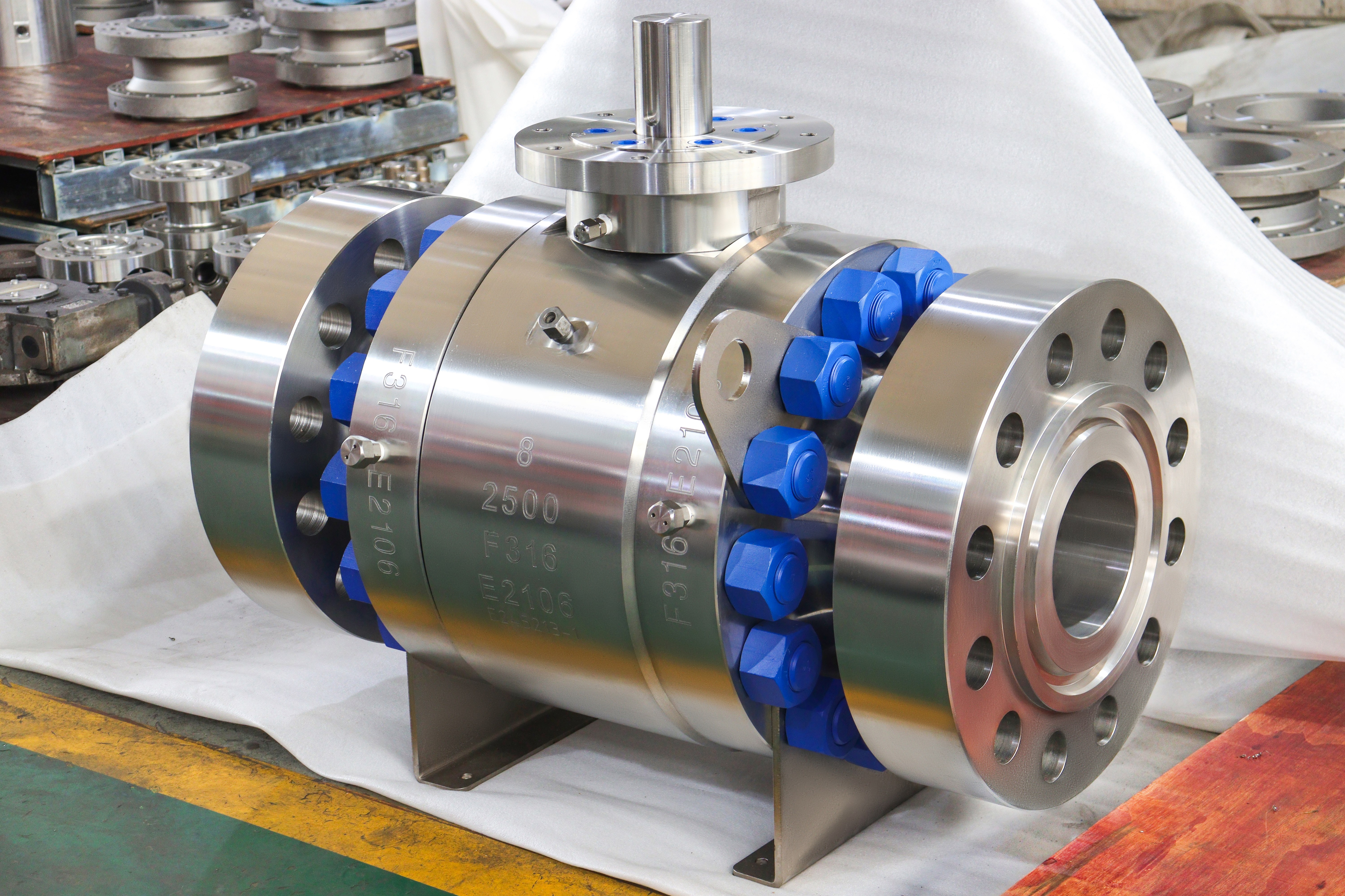
Every catalogue page for a three piece ball valve says the split body makes maintenance easy, and on a Class 150 water line it does. At Class 2500 the same sentence is doing something else, because the split was not put there for the maintenance crew. It was put there for the machine, and the maintenance access is what the buyer gets as a side effect.
The valve photographed here is a six by four inch Class 2500 body in F316 with a gearbox on a stand, a support foot under the centre section, and ring joint faces at the ends. The body is three pieces: a centre section holding the ball and both seats, and two end pieces bolted to it. Two bolted joints run round the body, each with its own ring of studs and its own gasket.
The claim of this page is a manufacturing one: at this class the body is split because the centre section has to be machined on both faces from one setting and because each piece has to be small enough to forge and to be examined as a forging. That is a different reason from the maintenance story, and it has a different cost, because two joints are two places where a Class 2500 body can leak to atmosphere.
Design and Construction
The centre section carries two seat pockets, one on each face, and they have to be coaxial to a tolerance that a one piece body would force the machine to reach through a long bore. Splitting the body means each pocket is cut from its own end, on the same machine, in the same programme, and the two faces are then closed by end pieces that are identical to each other. One drawing, one casting or forging number, one machining programme for the pair.
The third piece is not needed to get the ball into the body at this size, and that is worth admitting because the usual explanation says it is. The ball here is four inch and the end opening is six inch, so the ball passes through either end piece. What the third piece buys is the machining access described above and a shorter end piece that is easier to forge, and what it costs is one extra joint.
Each joint is a spigot and recess with a gasket between the faces, closed by a ring of studs. The spigot centres the two pieces and keeps the bores aligned; the gasket does the sealing; the studs provide the preload. At Class 2500 the preload is high, and the gasket has to be one that carries metal, which in practice means a spiral wound gasket with a stainless winding and a graphite or PTFE filler rather than a sheet gasket.
The gearbox sits on a raised stand rather than directly on the stem. The stand carries its own bearings, so the operating torque is reacted by the stand and not by the stem packing, and it puts the handwheel at a height a person can work at. A stand is a layout decision: it changes the space the valve needs above the pipe, and it has to be on the drawing before the pipe is routed.
Under the centre section there is a foot, a plate that lands on a structural support. On a Class 2500 valve of this size the mass is carried by that foot rather than by the two pipe flanges, which is why the foot appears on high pressure builds and not on small ones.

Material Options
The body, the ends, the ball and the stem on this build are all F316, and the pressure retaining parts carry the same heat number so that one certificate covers the set. The parts that are chosen separately are the seat, the body joint gasket and the studs, and those three are where the cost and the risk sit.
| Part | Material on This Build | Why It Is Separate |
|---|---|---|
| Centre section | A182 F316 forged | Carries both seat pockets |
| End pieces | A182 F316 forged | Identical to each other, one drawing |
| Ball and stem | F316, stem optionally 17-4PH | Trim wears, body does not |
| Seat | PTFE, reinforced PTFE, or metal | Sets the temperature limit |
| Body joint gasket | Spiral wound, stainless winding | Two of them, one per joint |
| Studs and nuts | B8M class 2 | Nickel alloy where the medium asks |
| Packing | PTFE or graphite | Graphite above the polymer limit |
The gasket choice is not a commodity decision at this class. A spiral wound gasket with a stainless winding and a graphite filler is a metal bearing gasket that recovers some of its thickness when the bolt load is released, and that recovery is what keeps the joint tight through a thermal cycle. A filled PTFE gasket has better chemical resistance and no recovery, and on a 2500 joint the loss of recovery is the leak.
The stem is the one trim part where a change of grade is normal rather than exceptional. F316 is the default, and 17-4PH precipitation hardening stainless appears where the stem has to be harder at the packing and at the drive. That substitution does not change the body rating, and it does not appear on the body stamp, so it has to be read from the certificate for the stem.
Technical Specifications
| Item | Value |
|---|---|
| Size range | Two inch to fifty six inch, DN 50 to DN 1400 |
| Pressure class | Class 150 to Class 2500, PN 20 to PN 420 |
| Build shown | Six by four inch, Class 2500, F316 |
| Body | Three piece, two bolted joints |
| Bore | Reduced, four inch through a six inch body |
| Ends | Ring joint or raised face to ASME B16.5 |
| Face to face | ASME B16.10 for six inch Class 2500 |
| Temperature | Minus 46 to plus 200 Celsius, seat dependent |
| Operator | Gearbox on a stand, or actuator on the pad |
| Support | Foot under the centre section |
| Design | API 6D, ASME B16.34 |
| Test | API 598 shell and seat, both joints named |
The size range on the family page runs from two inch to fifty six inch, and this page is anchored on the six by four inch Class 2500 build in the photograph. The range belongs in the attribute block and not in the title, because a page that claims fifty six inch and shows a six inch valve is a page that ranks for the wrong query and answers it badly.
The PN figure beside Class 2500 is 420, and it comes from the seven designations in API 6D rather than from a conversion. Class 600 is PN 100, Class 900 is PN 150, Class 1500 is PN 250, Class 2500 is PN 420. The pairing is worth printing because the errors on catalogue pages are almost always in this line.
Standards and Compliance
| Requirement | Document | What It Means Here |
|---|---|---|
| Product requirements | API 6D | Design, materials, welding, marking |
| Wall and rating | ASME B16.34 | Class 2500 for the group set by F316 |
| Flanges | ASME B16.5 | Facing, bolt circle, facing height |
| Pressure test | API 598 | Shell at 1.5 times, seat at 1.1 times |
| Fire test | API 607 or ISO 10497 | Type test against a stated scope |
| Material certificate | EN 10204 3.1 | One line per pressure part |
| Casting quality | Not applicable | All three pieces are forged |
The absence of a casting standard on that list is the point of the material choice. A three piece body in forged material has no pattern, no riser and no shrinkage porosity, and the examination that replaces the casting inspection is ultrasonic or magnetic particle testing of each piece at an acceptance level the buyer states.
The fire test row applies to the two body joints as well as to the seats. A joint that is tight cold and weeps when the gasket burns away is a joint that has not been considered in the fire case, and the spiral wound gasket with a graphite filler is the reason the joint survives it.
Manufacturing Process
Each of the three pieces starts as a forged billet or a rolled ring, is machined, and is examined before assembly. Forging at this class is what makes the examination meaningful: a forging has a grain flow that follows the shape and no internal voids, so an ultrasonic indication in it means something specific, and the report that comes back can be read.
The centre section is the piece that decides the accuracy of the valve. Both seat pockets are cut from the two faces on one setting, and the distance between them sets the space the ball and its seats occupy. That distance is what makes the ball seal on both sides at once, and it is why the centre section is not a part that can be swapped between suppliers.
The end pieces are identical, which halves the drawing and machining work and, more importantly, means a mistake in one is a mistake in both rather than a mismatch between two different parts. The joint face on each is machined after stress relief, and the spigot diameter is checked against the recess in the centre section rather than against a drawing dimension.
Assembly closes the joints with new gaskets, tensions the studs in a cross pattern in at least two passes, and then the whole body is tested. The test is what proves the joints, and it is done after assembly because a joint that was checked before the studs were tensioned has not been checked.

Quality Control and Testing
| Step | Check | Acceptance |
|---|---|---|
| 1 Incoming | Heat number against the mill certificate | Chemistry and mechanicals |
| 2 Examination | Ultrasonic or magnetic particle, per piece | Acceptance level stated |
| 3 Machining | Seat pocket spacing and coaxiality | Drawing, one setting |
| 4 Joint fit | Spigot against recess, gasket compressed thickness | Drawing |
| 5 Shell test | Body and both joints at 1.5 times | API 598, no leakage |
| 6 Seat test | Each seat at 1.1 times, both directions | API 598 rate |
| 7 Torque | Operating torque recorded at the works | Feeds the actuator selection |
| 8 Final | Faces protected, bores capped, crated | Works standard |
The torque row is the one that pays for itself later. A gearbox and an actuator are both selected from the torque a valve needs, and the only figure that describes this valve is the one measured on it. A catalogue figure for six inch Class 2500 covers a family of builds with different seats, and the spread inside that family is wider than the margin an actuator is usually bought with.

Applications and Industry Service
This body belongs on high pressure process lines where the medium is aggressive enough to require stainless and the pressure is high enough that the joint detail matters: chemical injection, high pressure water, urea service, and the high pressure sections of a synthesis loop. In those places the valve is a block valve, opened and closed fully, and its job is to be tight rather than to modulate.
The three piece build earns its place in those services when the valve has to be repaired in situ rather than replaced. Breaking both joints gives access to the ball, both seats and both trunnion bearings without cutting the pipe, and on a Class 2500 line with a welded spool on either side that access is worth more than the extra joint costs.
It is the wrong choice where the line cannot tolerate a second and third gasketed joint at all, which is the case on some hydrogen and oxygen services where the joint count is itself a hazard review item. In those services a fully welded body is used and the three piece argument does not apply, however convenient the maintenance story sounds.

Installation, Operation and Maintenance
The valve goes in with the pipe supported on both sides and the mating faces clean and parallel. The foot under the centre section is set on its support before the flange studs are tensioned, so that the valve is carried by the structure and not by the pipe, and the gap under the foot is shimmed rather than closed by pulling the pipe down.
When a body joint is broken, the gasket is replaced and the studs are renewed as a set. A stud that has been tensioned to a Class 2500 preload has been taken to a stress that does not repeat, and reusing it is a decision that has to be made against a torque figure rather than by eye. The joint faces are cleaned until no trace of the old gasket is left in the serrations, because a spiral wound gasket seals against those serrations and a filled one does not.
Operation is quarter turn through the gearbox, fully open or fully closed. The gearbox on the stand has its own lubrication and its own end stops, and the stops are set at the works so that the ball does not over travel and load the seat on the back face. A gearbox taken off and refitted has to have its stops reset, which is why the stand and the box should be treated as one assembly.
How to Specify and Order
Four things define this valve beyond the usual six entries, and all four are on the body rather than in the trim. The first is the facing at each end. The second is whether the body joints are to be tested and reported separately. The third is the position and height of the gearbox stand, because it has to be in the piping layout. The fourth is the foot, which needs a support under it that somebody has to design.
The order should also state the acceptance level for the examination of each forged piece. Ultrasonic examination at two different acceptance levels produces two different reports on the same forging, and a buyer who writes only that the body is to be examined has left the level to the works. That single line is the difference between a forging and a forging that has been looked inside.
Documents to name: the EN 10204 3.1 certificate covering the centre section and both end pieces, the ultrasonic or magnetic particle reports with their acceptance levels, the shell test record naming both body joints, the seat test record per seat and per direction, and the general arrangement drawing with facing, face to face, gearbox stand height and foot position.
FAQ
Q: Is a three piece body really easier to maintain?
A: It is, and that is not why it is split at this class. Both joints can be broken with the valve in the line, which gives access to the ball and both seats without cutting pipe. The split was put there so the body could be made, and the access is what the buyer gets as a result.
Q: Why not a two piece body at Class 2500?
A: A two piece body works, and it is used where the end opening passes the ball. The three piece body wins because both seat pockets are cut from opposite ends on one setting and because both end pieces are the same part, which halves the machining programme and the drawing work.
Q: What does the extra joint cost?
A: One more gasket, one more stud ring and one more place where a Class 2500 body can leak to atmosphere. On a hazardous service that joint count is a hazard review item, and on some hydrogen and oxygen services a welded body is used instead for that reason alone.
Q: Why is there a foot under the centre section?
A: Because the body is heavy and the pipe flanges are not designed to carry it. The foot lands on a structural support and is shimmed before the flange studs are tensioned, so the structure carries the valve and the flanges only have to seal.
Q: How is the body joint gasket chosen?
A: By what it has to do, not by what it is made of. At Class 2500 the gasket carries metal, which in practice is a spiral wound type with a stainless winding, because it recovers some thickness when the bolt load is released and that recovery keeps the joint tight through a thermal cycle.



Hot Products


News
Remanufactured Ball Valves: Five Checks That Decide Whether A Rebuild Deserves A Certificate
A rebuild at 45 percent of price with half the life is no saving. Five checks that separate a real remanufacture from a repaint with a certificate.
Read More
The Squeeze Is A Residual: How Tolerance Stack-Up Decides Whether A Ball Valve Seals
No dimension sets the seat squeeze. Five tolerances do, in series. Why identical valves feel different, and why a new ball changes the arithmetic.
Read More
Why A Ball Valve Gets Harder To Turn: Five Causes, And The Test That Tells Them Apart
A ball valve that stiffens over months points at one of five parts. Measure torque with the line pressurised and again vented, and the split becomes visible.
Read More
The Ball Valve at Four Thousand Bar: Seat Load, Erosion And Fatigue in Waterjet Circuits
At 4,000 bar a 10 mm bore puts 31 kN on the seat and a 0.1 mm leak cuts steel. What a ball valve must survive in a waterjet or intensifier circuit.
Read More