


CHINA J-VALVES Offers Various High-quality I ndustrial Ball Valves
J-VALVES, a distinguished professional ball valve manufacturer rooted in China, takes pride in its extensive product portfolio. Our offerings span a wide range, including trunnion-mounted ball valves, floating ball valves, high-temperature ball valves, high-pressure ball valves, metal-sealed ball valves, ultra-low temperature ball valves, DBB ball valves, Three-way And Four-way Ball Valve, and fully welded ball valves. Each product is a testament to our commitment to precision engineering and reliable performance. Meticulously crafted, they are designed to not only meet but exceed the most stringent industrial demands, ensuring stable operation even under extreme conditions. This enables us to provide our clients with high-value services and makes our valves widely sought-after in industries.
Product Category
Contact Us

-
J-VALVES-Q367F
-
J-VALVES
Overview of the J-VALVES extended stem fully welded ball valve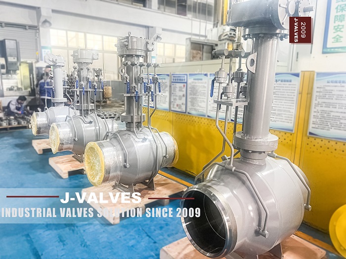
Bury a valve and you have made a decision that is easy to sign and hard to undo. The valve itself is fine underground; what changes is that every part a person might one day need is now behind a metre of soil. An extended stem exists to move the reachable parts back to where a person can stand, and how well it does that is decided by what comes up, not by how long the column is.
This is a fully welded trunnion valve from two to fifty six inches, Class 150 to Class 2500, with a forged carbon steel body and an operator raised above the body on a column. The body has no bolted joint, the ends are welded, and the column can be ordered to whatever height the burial puts it at.
The original page explains the extension as a convenience for environments with limited space. That is the wrong reason and it leads to the wrong questions at the quotation stage. Nobody raises a handwheel two metres into the air because the space is tight. They raise it because the valve is going into the ground, under insulation, or through a wall, and the operator has to end up on the side where people are.
Design and Construction
The body is the same welded shell used across this family: a forged ball chamber with welded end pieces, a trunnion mounted ball, two seats and a stem that comes out through the top. The ends carry a machined bevel for the pipe weld, and the bottom carries a drain.
The difference is the top. Instead of a gear operator sitting on the body neck, there is a short neck, a bolted flange, a column, a second bolted flange and then the gear. On the photograph both joints are visible along with two thin lines that run from the body shoulder up to the operator level and end in fittings.
That photograph is the whole argument of the page in one image. An extension is not a longer stem. It is a stack of parts added to the pressure envelope, and each part added is a joint, a surface to corrode and a place where the alignment of the stem has to be held over a longer distance.
The stack also changes the loads. On a valve at grade the operator sits a short distance above the body and the stem is short and stiff. On a column the gear is a weight at the end of a lever, and the stem runs through a tube that has to stay straight enough for it to turn. Nothing about that is difficult, and all of it has to be designed rather than assumed.

What Comes Up To Grade
Start with the stem, because it is the part everybody counts. The stem has to reach the operator, so it is extended, and its length is set by the burial. That is the easy half, and it is the half the original page describes.
Now count the other things that might need to reach the surface. A seat leak on a buried valve cannot be fixed by injecting sealant at the body, because the body is underground. A cavity that has to be bled before maintenance cannot be bled at the body either. If those operations are going to happen at all, the lines that serve them have to come up too, and on this valve two of them do.
| What Reaches Grade | What It Lets You Do | What It Does Not Let You Do |
|---|---|---|
| Stem only | Operate the valve | Inject sealant, bleed the cavity |
| Stem and sealant lines | Operate, and nurse a seat leak | Bleed the cavity independently |
| Stem and cavity lines | Operate, and bleed the cavity | Reach the seats themselves |
| Stem, lines and a pit | All of the above, with access to the body | Anything, if the pit floods |
The table is the reason to ask for a drawing rather than a length. Two valves quoted at the same column height can differ completely in what the operator can do from the surface, and the difference shows up in the number of lines beside the column, not in the dimension.
The next question is where the stem seal sits, because that decides whether the column holds pressure. There are two ways to build the extension and they look almost identical in a photograph.
| Feature | Dry Column | Wet Column |
|---|---|---|
| Packing position | On the body neck, below the column | At the top of the column, under the gear |
| Column contents | Stem and air | Stem and line pressure |
| Column joints | Location only, not pressure joints | Pressure joints, both of them |
| Leak symptom | Nothing until the body packing fails | A weep at a joint above ground |
| Field shortening | Possible without isolating | Not possible without isolating |
A dry column is a shroud. The stem runs up inside it, the packing stays on the body where it can be reached only by excavation, and the bolted flanges at each end locate the tube rather than seal it. It is simple, and its weakness is that the one seal which matters is the one you cannot reach.
A wet column puts the packing at the top, under the operator, where a person can tighten it with a wrench while standing up. That is a real advantage, and it comes at a price: the column and both of its bolted joints now hold line pressure, and they are the only pressure joints on the whole valve that sit underground where nobody can see them weep.
Which one is on the drawing matters more than any other line in the quotation, because the two designs have opposite failure modes. A dry column fails at the body packing and requires digging. A wet column can be re-packed from the surface but adds two hidden pressure joints. Neither is wrong; a buyer who does not know which one they have is.
Technical Specifications
The table follows the factory data. The pressure line on this page is already written in the standard designations, which is worth noting because the sibling pages of this family are not consistent about it.
| Item | Value |
|---|---|
| Size range | 2 inch to 56 inch, DN 50 to DN 1400 |
| Pressure class | Class 150 to Class 2500, PN 20 to PN 420 |
| Temperature | Minus 46 to plus 200 Celsius, material dependent |
| Body | Forged carbon steel A105, one piece welded shell |
| Column | Welded or bolted spool above the body neck |
| Column joints | Bolted flanges top and bottom |
| Ball | Hardened stainless or alloy steel, trunnion mounted |
| Stem | Stainless or alloy steel, extended, anti blow out |
| Seat, soft | PTFE or RPTFE at the lower end of the range |
| Seat, metal | Hardfaced ring for high temperature and abrasive duty |
| Seat design | Single or double piston effect, stated on the order |
| Body ports | Drain at the bottom, injection ports on request |
| Lines to grade | Two small bore lines beside the column |
| Ends | Butt weld per ASME B16.25, or socket weld |
| Face to face | ASME B16.10 for the size and class |
| Operation | Handwheel and gear, pneumatic, or electric |
| Design standard | API 6D and ASME B16.34 |
| Test standard | API 598, shell and seat |
| Fire test | API 607 and API 6FA on the design |
| Anti static | Device fitted, continuity checked at assembly |
Two lines in that table are the ones to argue about at the quotation stage. The column line says welded or bolted because both exist in the family, and the photograph on this page shows bolted; the choice changes whether the column can be shortened on site. The lines to grade line is a count, and a count is the cheapest thing in the whole quotation to get wrong.
Standards and Compliance
API 6D covers the valve and says nothing useful about the column, which is why the extension is usually treated as an accessory in the paperwork and as a pressure part in reality. The gap between those two views is where the arguments happen.
The body is designed to API 6D and rated to ASME B16.34, its flanges are to ASME B16.5 and its weld ends to ASME B16.25. None of those documents describes a spool bolted on top of a valve, so the column inherits the class of the valve it sits on and nothing else. That is a reasonable convention and it is not a test: the column is a flange pair and a tube, and what makes it safe is the gasket, the bolting and the alignment, all of which are decided by the supplier rather than by a standard.
The practical consequence is that the shell test proves the body and not the column. A test procedure that pressurises the valve with the column fitted will find a leaking column gasket; a procedure that tests the body before the column goes on will not. On a valve that is going underground, the second procedure is the one that produces a surprise in year three.
The same logic applies to the fire test. API 607 is run on the design, which means a representative valve with its seats, its packing and its body joints. Whether the column joints were part of that test valve is a question worth asking, because a gasket that was never in the fire test is a gasket whose behaviour at temperature is unknown, and on a wet column that gasket is under the road.
The flange standard is the other loose end. If the column joints are B16.5 flanges, they are sized by the class and the gasket is a standard part, which is good. If they are proprietary joints, the gasket is a factory item and a leak above ground becomes a purchase order and a wait.
Manufacturing Process
The body is built as it is on every valve of this family: forged, normalised, machined, welded, stress relieved and shell tested. The column is a separate part and it is made to a length, which means it is made after the order and not before it.
The column is machined from pipe or bar, with a flange at each end and a bore that will pass the stem. Its two critical features are the flange faces, which have to be square to the bore, and the bore itself, which has to be straight over its whole length. A column that is straight to the eye and out by a little over two metres will hold the stem in a bend, and the stem will not turn as freely as it did on the bench.
The stem is made in one piece to the full length. A jointed stem is possible and is sometimes offered, but a joint inside a tube is a place where backlash and corrosion both live, and the extension is the one part of this valve that nobody will ever inspect from the inside.

Quality Control and Testing
The body is tested before the column is fitted, which is the sequence that makes sense and the sequence that leaves the column joints untested. The way to close that gap is to test again with the column on, or to specify that the column joints are included in the shell test, and either answer has to be written into the order.
The stem runout is checked at the top of the column, not at the body, because that is where the error accumulates. A dial gauge on the top of the stem over one turn tells you whether the column and the stem agree, and it is a check that takes a minute on the bench and is impossible in a trench.
The lines to grade get their own pressure test, and this is the step that is most often skipped because they are small. They are small bore, they have fittings at both ends, and they carry whatever the body carries. A small bore line that was never tested is not a minor omission on a valve that cannot be dug up.

Applications and Industry Service
The usual home for this valve is a buried pipeline with the operator in a pit or at grade: transmission lines, gathering systems, water and district heating mains, and the inlet valves of a metering station where the pipe runs underground and the meter does not.
It is also used where the valve is inside a structure rather than under the ground: below a floor, inside a wall penetration, or under a thick insulation system where the handwheel would otherwise be buried in lagging. The problem is the same in each case, which is that the operator has to be on the accessible side of a barrier.
The design is a poor fit where the column would be in the way of traffic, where the operator would need a platform nobody wants to build, or where the valve may have to be removed and the column makes it taller than the lifting envelope. Those are layout questions, and they are cheaper to answer before the length is fixed.

Installation, Operation and Maintenance
The valve is welded in with the column fitted or with the column removed, and the choice matters. Fitting it afterwards means the column joints are made in the trench, where the torque and the alignment are both harder to control than on a bench.
The column is not a lifting point, not a step and not a support for anything. It is a tube with a stem inside it, anchored to the valve body at one end and carrying a gear at the other. Load applied to it in the middle goes straight into the stem alignment, and an operator who has used it as a foothold will find out at the next quarter turn.
Maintenance is the packing, the gear, the lines and the paint. The packing is the first item and its location is the one thing that decides whether maintenance is a wrench job or an excavation. The gear is the second, because a gearbox on top of a column collects water unless the breather and the seals are sound.
How to Specify and Order
An order for this valve needs the column height, and it needs three other lines that the height does not imply. Write them together or the drawing will come back with the wrong one of each.
| Line on the Order | What to Write | Why It Matters |
|---|---|---|
| Column height | The dimension from the body centre to the operator | It is set by burial, not by preference |
| Column type | Dry or wet, and where the packing sits | It decides whether the joints hold pressure |
| Column joints | Bolted or welded, and whether they are in the shell test | An untested joint underground is a gamble |
| Lines to grade | How many, and what each one serves | A count, and the cheapest thing to get wrong |
| Stem | One piece to full length, or jointed | A joint inside a tube is never inspected |
| Ends | Butt weld with the pipe wall, or socket weld with a size limit | The bevel follows the pipe |
| Body material | A105, or a low temperature steel | Minus 46 is below what A105 does |
| Test | Body, column joints, and the small bore lines | The body test does not cover the rest |
| Operation | Handwheel and gear, or an actuator on the top flange | The top flange has to match the drive |
| Marking | Size, class, grade and heat number | It is what the buyer will ask for later |
FAQ
Q: Why is an extended stem fitted?
A: Because the valve ends up somewhere a person cannot stand: buried, under insulation, below a floor or inside a wall. The operator has to be on the accessible side of that barrier, so the stem is extended and the gear is mounted at the top. Convenience is the result, not the reason; burying the valve is the reason.
Q: What is the difference between a wet and a dry column?
A: It is where the stem packing sits. In a dry column the packing stays on the body neck and the column is only a shroud, so its bolted flanges locate the tube and hold no pressure. In a wet column the packing is at the top, under the gear, so the column and both of its joints hold line pressure and sit underground.
Q: Which is better?
A: Neither, and the choice is a statement about which maintenance you expect. A dry column keeps the pressure joints where they can be tested and puts the one seal that matters out of reach. A wet column lets the packing be tightened from the surface and adds two hidden pressure joints. The wrong answer is not knowing which one is on the drawing.
Q: Why do two small lines run beside the column?
A: Because some operations cannot be done at the body once the valve is buried. A sealant line lets a seat leak be nursed from grade, and a cavity line lets the body be bled before maintenance. Each line is a pressure part with fittings at both ends, and none of them is covered by a shell test that was run before the column was fitted.
Q: Does the column make the valve taller for shipping and lifting?
A: It does, and the column is not a lifting point. The body carries its own lugs and the column is a tube with a stem inside it, anchored at one end and holding a gear at the other. Load applied to the middle of it goes into the stem alignment, and a stem held in a bend will not turn as freely as it did on the bench.



Hot Products


News
A Ball Valve Is A Tuning Fork: Vibration, Fretting And The Joints That Only Hold By Friction
A ball valve holds seat, stem and body joint by preload alone. Vibration turns that preload into micro-motion, and the wear arrives with no cycle at all.
Read More
Urea Plant Ball Valves: The Wetted Path Survives Only While Oxygen Is Being Fed To It
Carbamate at 150 bar and 185 C eats stainless 50 times faster once the passive film starves. The valve cavity is where the oxygen runs out first.
Read More
Stiction: What A Ball Valve Becomes When Nobody Turns It
A valve that stood closed for years has not worn out. The seat has bonded to the ball, and the first stroke is a step, not a ramp. What the trace shows.
Read More
Molten Salt Ball Valves: The Valve Works at 565 C And Dies at 219 C
Salt freezes at 220 C and decomposes at 565 C. Everything a molten salt ball valve does happens in that 345 kelvin gap, and the gap is not generous.
Read More