


CHINA J-VALVES Offers Various High-quality I ndustrial Ball Valves
J-VALVES, a distinguished professional ball valve manufacturer rooted in China, takes pride in its extensive product portfolio. Our offerings span a wide range, including trunnion-mounted ball valves, floating ball valves, high-temperature ball valves, high-pressure ball valves, metal-sealed ball valves, ultra-low temperature ball valves, DBB ball valves, Three-way And Four-way Ball Valve, and fully welded ball valves. Each product is a testament to our commitment to precision engineering and reliable performance. Meticulously crafted, they are designed to not only meet but exceed the most stringent industrial demands, ensuring stable operation even under extreme conditions. This enables us to provide our clients with high-value services and makes our valves widely sought-after in industries.
Product Category
Contact Us

-
J-VALVES-Q367F
-
J-VALVES
Overview of the J-VALVES DIB-1 fully welded ball valve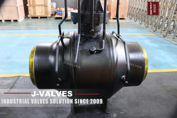
A double block and bleed valve earns its price in one moment: the afternoon someone closes it, opens the bleed, and finds the cavity still holding pressure a day later. Everything before that moment is paperwork. DIB-1 is not a marketing label for a good seat; it is a specific arrangement of two seats, and the arrangement decides what the valve can prove and what it cannot.
This is a fully welded trunnion valve from two to fifty six inches, offered from Class 150 to Class 2500, with forged carbon steel bodies and a choice of polymer or metal seats. The body has no bolted joint, the ends are butt welded or socket welded, and the operator can be a handwheel, a pneumatic cylinder or an electric drive.
The label at the top of the original page says DIB-1 and then describes both seats as double piston effect, which is exactly right. Two sections further down, the feature list says single or double piston effect, which is the generic sentence used on every page of this family and quietly contradicts the label. That single line is where the whole page turns, because a buyer who reads it will assume the seats can be ordered either way, and DIB-1 is not an option.
Design and Construction
The body is forged, welded and painted as one shell. There is no body gasket, no ring of studs around the middle, and therefore no joint that can weep into a pit. The ball is carried on an upper and a lower trunnion so that the pressure load goes into the body through the bearings instead of into the downstream seat.
Both ends of the valve are prepared for a weld. On the photograph the preparation is visible as a bright machined band at each end, which is the bevel that meets the pipe wall. Between the two bevels the shell is continuous, and the only interruptions are the stem at the top, the ports on the flanks and the drain at the bottom.
That sentence is the physical description of the design and also its constraint. A bolted body can be opened to reach the seats, the ball and the cavity. A welded body cannot. Everything that will ever be done to this valve has to be done through the stem, the ports or the pipe.
The comparison is worth making because the two versions are ordered for different reasons and fail in different ways. A valve at grade can be inspected, bled and re-packed from a standing position. A valve under a road has none of that, and the design has to move the only part a person can reach up to where a person can stand.

DIB 1 Removes The Relief, Not The Seal
A seat in a trunnion valve is a ring that is pushed against the ball. What pushes it is partly a spring and partly the line pressure, and the direction the line pressure acts is the whole difference between the seat types. Get this one idea and the rest of the page follows.
A single piston effect seat is arranged so that line pressure pushes it onto the ball from the upstream side, while pressure arriving from the cavity side pushes it away. That second behaviour is the relief: if the cavity pressure rises above the upstream pressure, the seat lifts and the cavity vents into the line. It is a safety feature built into the geometry, and it costs nothing.
A double piston effect seat is arranged so that pressure pushes it onto the ball from both sides. The cavity can no longer push the seat off, so the seat seals in both directions and the cavity stays closed. That is what makes double block and bleed work as a proof: with the valve closed and the cavity bled, each seat is holding on its own, and the bleed tells you which one is passing.
| Seat Design | Single Piston Effect | Double Piston Effect, DIB 1 | Combined, DIB 2 |
|---|---|---|---|
| Bi-directional sealing | Yes | Yes | Yes |
| Body cavity self relieving | Yes | No | Yes |
| Double barrier | No | Yes | Yes, preferred direction only |
DIB-1 is the middle column: both seats double piston effect, double barrier in both directions, and no self relief anywhere. DIB-2 is the third column, one seat of each type, which keeps the double barrier in the preferred direction and puts the relief back. The two designs look identical from outside and are told apart by the drawing and the seat test, not by the paint.
The consequence of the middle column is that the cavity becomes a closed pressure vessel. Liquid trapped between two closed seats does not compress, and when it warms up it expands. The pressure rise goes into the body wall and into the seats, and there is no path out except the port that somebody has to open. On a pipeline that is started cold and runs warm, that is a routine event, not an accident.
So the honest way to describe DIB-1 is that it buys certainty and it sells off a safety valve. The certainty is that neither seat can be lifted by cavity pressure, which is why the design is specified where a passing seat is unacceptable. The price is a written bleed procedure: before the line warms up, before a hydrostatic test is left standing, and before the valve sits closed between two blocked volumes.
Technical Specifications
The table follows the factory data, with two lines tightened. The pressure range is written in classes with the standard designations beside them, and the end line carries the size limit that the original page leaves out.
| Item | Value |
|---|---|
| Size range | 2 inch to 56 inch, DN 50 to DN 1400 |
| Pressure class | Class 150 to Class 2500, PN 20 to PN 420 |
| Temperature | Minus 46 to plus 200 Celsius, material dependent |
| Body | Forged carbon steel A105, one piece welded shell |
| Ball | Hardened stainless or alloy steel |
| Stem | Stainless or alloy steel, anti blow out |
| Seat, soft | PTFE or RPTFE at the lower end of the range |
| Seat, metal | Hardfaced ring for high temperature and abrasive duty |
| Seat arrangement | Both seats double piston effect, DIB-1 |
| Cavity relief | None. Bleed through the body ports |
| Body ports | Two flank ports and one drain, plugged |
| Ends | Butt weld per ASME B16.25, or socket weld |
| Face to face | ASME B16.10 for the size and class |
| Operation | Handwheel, pneumatic, or electric |
| Design standard | API 6D and ASME B16.34 |
| Test standard | API 598, shell and seat |
| Fire test | API 607 and API 6FA on the design |
| Anti static | Fitted, continuity checked at assembly |
| Marking | Size, class, grade and heat number on the shell |
The temperature line is worth a second look. Minus 46 Celsius is not a carbon steel A105 figure; A105 is normally taken to about minus 29, and going lower means either a low temperature steel such as LF2 or a documented impact test. The page lists A105 as an example and then a range that starts below what A105 does, so the material has to be confirmed against the temperature rather than assumed from the first line.
The end line has the same shape of problem in the other direction. Butt weld and socket weld are both offered with no size boundary, but a socket weld end belongs to small bore work and a DN 1400 valve is a butt welded valve. A data sheet that offers both across the whole range is telling the buyer that nobody has checked the two against each other.
Standards and Compliance
API 6D and ASME B16.34 do most of the work on this valve, and the rest is split between the weld end, the fire test and the seat test. The one standard that does not belong is API 608, which the original page lists beside the other two.
| Document | What It Fixes | What It Does Not Cover |
|---|---|---|
| API 6D | Valve design, test, marking, cavity relief | Seat type, which is the buyer's choice |
| ASME B16.34 | Wall thickness and pressure temperature ratings | The weld end preparation |
| ASME B16.25 | Butt weld end geometry | Anything above the pipe wall it is cut for |
| API 598 | Shell and seat test at ambient | Cavity behaviour after a thermal cycle |
| API 607 | Fire test of the design | Every valve, which is not tested one by one |
| API 608 | Small steel ball valves, to DN 600 and Class 600 | A DN 1400 valve, which is outside it |
| NACE MR0175 | Hardness limits for sour service | The hardness of a hardfaced seat |
API 608 is a real standard and it is the right one for a small floating valve. It stops at DN 600 and Class 600, and this page runs to DN 1400 and Class 2500, so citing it here does not extend the scope of the standard, it just tells a knowledgeable buyer that the compliance list was assembled rather than checked.
The weld end needs its own sentence because it is the joint that fails first. ASME B16.25 gives the bevel geometry, but the bevel is cut to the pipe wall, and the pipe wall comes from the pipe schedule. A valve ordered with a bevel for one wall thickness and welded to another will have a root gap nobody designed, and on a fully welded valve there is no second chance to get it right.
Manufacturing Process
The body starts as a forging, is normalised and rough machined, and then the bore, the seat pockets and the trunnion bores are cut. The trunnion bores are line bored from one set up so that the upper and lower bearings share an axis; if they do not, the ball tilts under load and the seat has to absorb the error.
The seat pockets are the tightest dimensions on the part, because the seat has to slide in them and seal against them at the same time. On a DIB-1 body both pockets are the same, which is one of the quiet economies of the design: there is no handed seat, no mirror image part, and no chance of fitting the two the wrong way round.
The shell is closed by welding the end pieces to the body. The welds are circumferential and full penetration, and each one is a permanent part of the pressure boundary. After welding the body is stress relieved, the weld caps are dressed, and the shell is tested before anything goes inside it.

Quality Control and Testing
The shell test is at the API 6D pressure for the class, with the body empty and the ends capped. After that the seats go in and the seat test is run in both directions with the cavity monitored through the bleed port, which is the test that DIB-1 exists to make meaningful.
On a DIB-1 valve the seat test has a shape that a single piston design cannot produce. Each seat is tested with pressure on the line side and the cavity open to atmosphere, and the seat has to hold with no relief path available. If a seat passes that test, it is holding on its own geometry and not on the help of a cavity that happens to be venting somewhere else.
The bleed port is a test point and a pressure part at the same time, and it is often the last thing checked. The plug, its thread, its seal and its torque belong on the test record, because the port is a penetration in a shell that cannot be opened, and the person who opens it in service has no way to know how it was closed.

Applications and Industry Service
The design is chosen where a passing seat is expensive: meter runs and custody transfer, compressor station isolation, tank farm manifolds, and the inlet and outlet of a metering skid where the valve has to prove zero flow before a calibration. In all of those the valve is closed for a long time and the proof of closure is the product.
It is also chosen where the line is buried or the valve is in a pit, because a welded body has no gasket to fail in a place nobody can see. That is the same reason the extended stem versions of this family exist, and the two features are usually ordered together.
DIB-1 is not the right choice where the trapped volume can warm up between two closed seats with no operator available. In that service the combined DIB-2 arrangement, with one seat that relieves, is the safer specification, and the page that sells DIB-1 should say so before the order rather than after the first thermal cycle.

Installation, Operation and Maintenance
The valve is welded into the line, so installation is a welding procedure rather than a bolting procedure. The ends are aligned, the root is purged, the heat input is controlled, and the valve is left part open during the work so that the seats are not damaged by heat or by debris falling into the bore.
Commissioning includes a stroke and a bleed. The stroke confirms that the ball turns through ninety degrees and that the stops are where the drawing says; the bleed confirms that the cavity can be emptied. On a DIB-1 valve the second check is not a formality, because a cavity that cannot be bled has no relief at all.
Maintenance is limited to what can be reached: the packing, the seats through the injection ports if they are fitted, the cavity through the drain, and the operator. Everything else is inside a welded shell. That is the trade the design makes, and it is worth stating plainly rather than describing the valve as maintenance free.
How to Specify and Order
An order for this valve has to settle the seat arrangement first, because the label DIB-1 is a commitment and not a preference. The rest of the lines are the ones that decide whether the valve can be built and tested to what was asked.
| Line on the Order | What to Write | Why It Matters |
|---|---|---|
| Seat arrangement | DIB-1, both seats double piston effect | The label is not an option list |
| Cavity plan | Bleed procedure and who operates it | DIB-1 has no self relief |
| Ports | Number, size and position of the plugs | They are the only access to the cavity |
| Body material | A105, or a low temperature steel | Minus 46 is below what A105 does |
| Ends | Butt weld with the pipe wall, or socket weld with a size limit | The bevel follows the pipe |
| Seat material | Polymer, or metal with the hardfacing stated | It sets the top of the temperature range |
| Test | Shell, and seat both directions with cavity monitored | One direction hides a cavity leak |
| Marking | Size, class, grade and heat number | It is the traceability the buyer will ask for |
| Fire test | API 607 on the design, with the certificate | A design test is not a unit test |
| Operation | Handwheel, pneumatic or electric, with the mounting | The top flange has to match the drive |
FAQ
Q: What does DIB-1 actually mean?
A: It means both seats are double piston effect. Each seat is pushed onto the ball by pressure from the line side and by pressure from the cavity side, so neither seat can be lifted by the cavity and the valve blocks in both directions. The B in DIB is bleed, and with both seats holding, the cavity can be bled and each seat proved on its own.
Q: Why does DIB-1 have no cavity relief?
A: Because relief is a property of the seat geometry. A single piston seat is pushed off the ball by cavity pressure, which is how the cavity vents into the line. A double piston seat is pushed onto the ball from both sides, so rising cavity pressure increases the sealing force instead of lifting the seat. Take away the relief and the cavity becomes a closed volume.
Q: What is the difference between DIB-1 and DIB-2?
A: DIB-1 is two double piston seats and DIB-2 is one of each. DIB-2 keeps the double barrier in one preferred direction and lets the cavity relieve in the other, so it gives up universal blocking in exchange for a relief path. From outside the two valves look the same and the difference is only visible in the drawing and in the seat test.
Q: Is a trapped cavity really a problem in service?
A: It is in any line that is started cold and runs warm. Liquid trapped between two closed seats cannot compress and expands when it heats, so the cavity pressure rises above the line pressure. On a DIB-1 valve that rise loads the body wall and the seats with no path out, so the bleed procedure has to be written before commissioning rather than discovered later.
Q: Why does the temperature range start below what A105 can do?
A: Because the page quotes a range for the whole family and names A105 as an example material. A105 is normally taken to about minus 29 Celsius, so a valve specified to minus 46 needs a low temperature steel such as LF2 or a documented impact test. The temperature and the material have to be chosen together, not read from separate lines.



Hot Products


News
A Ball Valve Is A Tuning Fork: Vibration, Fretting And The Joints That Only Hold By Friction
A ball valve holds seat, stem and body joint by preload alone. Vibration turns that preload into micro-motion, and the wear arrives with no cycle at all.
Read More
Urea Plant Ball Valves: The Wetted Path Survives Only While Oxygen Is Being Fed To It
Carbamate at 150 bar and 185 C eats stainless 50 times faster once the passive film starves. The valve cavity is where the oxygen runs out first.
Read More
Stiction: What A Ball Valve Becomes When Nobody Turns It
A valve that stood closed for years has not worn out. The seat has bonded to the ball, and the first stroke is a step, not a ramp. What the trace shows.
Read More
Molten Salt Ball Valves: The Valve Works at 565 C And Dies at 219 C
Salt freezes at 220 C and decomposes at 565 C. Everything a molten salt ball valve does happens in that 345 kelvin gap, and the gap is not generous.
Read More