


CHINA J-VALVES Offers Various High-quality I ndustrial Ball Valves
J-VALVES, a distinguished professional ball valve manufacturer rooted in China, takes pride in its extensive product portfolio. Our offerings span a wide range, including trunnion-mounted ball valves, floating ball valves, high-temperature ball valves, high-pressure ball valves, metal-sealed ball valves, ultra-low temperature ball valves, DBB ball valves, Three-way And Four-way Ball Valve, and fully welded ball valves. Each product is a testament to our commitment to precision engineering and reliable performance. Meticulously crafted, they are designed to not only meet but exceed the most stringent industrial demands, ensuring stable operation even under extreme conditions. This enables us to provide our clients with high-value services and makes our valves widely sought-after in industries.
Product Category
Contact Us

-
J-VALVES-Q676F
-
J-VALVES
Overview of the J-VALVES gas hydraulic actuated fully welded ball valve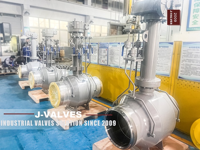
A gas hydraulic actuator is a way of using pipeline gas as the power source without venting it on every stroke. The gas is taken from the line at high pressure, used to push hydraulic oil, and the oil drives a piston that turns the valve. The gas stays on one side of a barrier and the oil does the work, which is why the arrangement is also called gas over oil. It is the standard drive for a remote line valve that has no air and no power.
This valve is a welded trunnion ball valve from two to fifty six inches, in classes 150 to 2500, with that actuator on top. The shell is forged, the ends are butt weld, the ball runs on trunnions and the seats are polymer or metal. The actuator is the part that makes the page interesting, because a gas hydraulic drive is not simply a pneumatic one with a different medium: it has its own logic, its own failure modes, and its own way of deciding when to close.
Two things on the original page are worth naming before anything else. The title says gas hydraulic actuated, and the operation line lists a handwheel, a pneumatic drive and an electric one, with no gas hydraulic option at all. The title also says fully welded, and the connection line offers flanged ends only. Both are copy errors from sibling pages, and both change what a buyer thinks they are ordering.
Design and Construction
The valve is the welded shell described elsewhere on this site: a pipe section with forged ends, circumferential seams, a trunnion mounted ball, seats in pockets and a stem through the top flange. The stem is fitted with a mounting pad or a bracket for the actuator, and the actuator is a self contained unit with a gas cylinder, an oil reservoir, a piston and a control block.
The gas side takes its supply from the pipeline, usually upstream of the valve, through a regulator and a filter. When the control block opens, gas pressure acts on the oil in a boost cylinder, the oil is displaced into the actuator cylinder, and the piston strokes the valve. Exhaust gas from the gas side is vented, which is the detail that decides whether the arrangement is acceptable on a given line.
The separation is the point of the design. Gas is compressible and oil is not, so a gas drive would move the valve in a way that depends on the gas pressure, while the oil drive moves it at a rate set by the oil flow. That is why the arrangement can close a large valve quickly and predictably, and why the same actuator can be set to close on a signal rather than to drift shut as pressure falls.
The block between the two media is where the maintenance lives. Filters clog, regulators drift, seals between gas and oil weep, and the oil level falls without anyone noticing because the reservoir is a small tank on a remote valve. A gas hydraulic actuator that has not been serviced is an actuator that will close the valve at the wrong moment, or fail to close it at the right one.

Line Break Is A Rate, Not A Pressure
A gas hydraulic valve is usually installed to close when the line breaks. The question is how the actuator knows. There are three common triggers, and they are not variations on one idea: a low pressure trip, a rate of pressure drop trip, and a remote command. Each of them can be made to work, and each of them can be made to trip at the wrong time.
| Trigger | What It Watches | What Makes It Trip Wrongly | Where It Fits |
|---|---|---|---|
| Low pressure trip | An absolute pressure below a set value | Normal drawdown at the end of a line, or a cold night | Lines with a stable supply and a known minimum |
| Rate of pressure drop | How fast the pressure falls | A valve upstream closing quickly, or a compressor trip | Long lines where a rupture is the real risk |
| Remote command | A signal from a control room or an ESD system | Loss of communication | Stations with SCADA and an operator watching |
The rate trip is the one that belongs on a transmission line, and the reason is simple. A rupture drops the pressure far faster than any normal operation can, because the volume that is escaping is not being replaced. A low pressure trip cannot tell a rupture from a line that is simply running at a lower pressure because demand fell, and it will either fail to trip or trip constantly and be bypassed by the operator, which is worse.
Setting the rate is a judgement, not a table lookup. The trip has to be faster than any normal transient, including a downstream valve closing and a compressor stopping, and slower than a rupture. Those two rates are far apart on a long line and close together on a short one, which is why the setting belongs to the pipeline engineer and not to the actuator supplier, and why a factory default is a starting point at best.
The third trigger is not a substitute for the first two. A remote command depends on communication, and a line break is exactly the event that takes the communication out. The usual arrangement is a rate trip as the primary and a remote command as an override, with the low pressure trip as a backstop if the operator wants one.
A gas hydraulic actuator that has closed on a trip does not reopen itself. The gas that drove it closed has been vented, the oil is on the other side of the piston, and the valve will stay shut until somebody pumps oil back by hand or recharges the system. That is deliberate: a valve that reopened by itself after a line break would defeat the purpose of closing it.
The first row is the one that gets forgotten in the design of a remote station. A valve that closes on a line break has to be reopened by somebody, and that somebody has to reach a hand pump on a valve that may be in the middle of nowhere. The pump, its access and the lighting are part of the installation, and a station designed without them has a valve that closes once and stays closed.
The second consequence is that the gas supply has to be maintained. A gas hydraulic actuator with an empty cylinder is an actuator that cannot open the valve, even though the valve itself is fine. The supply is taken from the line, so it is usually available, but the filter and the regulator between the line and the cylinder are the parts that fail, and they fail silently.
Technical Specifications
The table below keeps the factory data and corrects two lines that contradict the page's own title. The connection is written as butt weld with flanged ends as an option, because a fully welded valve with flanged ends only is not a fully welded valve. The operation line includes the gas hydraulic drive, because that is what the page is about.
| Item | Value |
|---|---|
| Size range | 2 inch to 56 inch, DN 50 to DN 1400 |
| Pressure class | Class 150 to Class 2500, PN 20 to PN 420 |
| Temperature | Minus 46 to plus 200 Celsius, material and seat dependent |
| Body | Forged A105 carbon steel, 304 or 316 stainless, or alloy steel |
| Body construction | Welded shell, butt weld ends standard |
| Ball | Hardened stainless or alloy steel |
| Stem | Stainless or alloy steel, with anti blow out shoulder |
| Seat | PTFE or RPTFE, or a metal seat for higher temperature |
| Packing | Graphite, wire reinforced |
| Ends | Butt weld to ASME B16.25, flanged RF on request |
| Actuator | Gas over oil, with gas cylinder, oil reservoir and control block |
| Actuator supply | Pipeline gas, regulated and filtered, with a minimum pressure stated |
| Trip logic | Rate of pressure drop, with remote ESD and low pressure options |
| Operation after trip | Manual pump to reopen, or a recharged supply |
| Face to face | ASME B16.10 for the size and class |
| Design standard | API 6D and ASME B16.34 |
| Test standard | API 6D and API 598 |
| Fire test | API 607 and ISO 10497, on the design |
The actuator lines are the ones to argue about at the enquiry. The minimum gas pressure at which the actuator will still stroke the valve is a number the supplier has to state, because it decides whether the drive works at the end of a line where pressure is low. The trip setting is a number the pipeline engineer has to state, because it decides whether the valve closes on a rupture or on a cold night.
Standards and Compliance
The valve is covered by API 6D and ASME B16.34, its ends by ASME B16.25, its fire behaviour by API 607. The actuator is covered by none of them. A gas hydraulic actuator is a pressure containing assembly in its own right, with a gas cylinder, an oil circuit and a control block, and the standards that apply to it come from the instrumentation and pipeline world rather than from the valve world.
| Document | What It Covers | What It Leaves Out |
|---|---|---|
| API 6D | Valve class, test, marking, cavity relief | The actuator and its gas circuit |
| ASME B16.34 | Body wall and ratings | The cylinder and the oil circuit |
| API 607 and ISO 10497 | Fire test of the valve design | The actuator, which is rarely in the scope |
| ASME B31.8 | Pipeline design, including valve spacing and ESD philosophy | The actuator's internal logic |
| IEC 61508 and 61511 | Functional safety of the shutdown function | The mechanical valve, which is assumed |
| The purchase order | The trip logic, the set points and the proof test interval | Everything above, unless written down |
The functional safety line is the one that decides whether the arrangement is acceptable on a high consequence line. A valve that is credited as a safety function has to be proof tested at an interval, and the proof test has to demonstrate that the trip works, not that the valve turns. That means a partial stroke test on the actuator and a full trip at a longer interval, and both have to be planned before the valve is installed, because a full trip on a line in service is a shutdown.
Manufacturing Process
The valve is built as any welded trunnion valve: shell welded, seams radiographed, internals inserted through the ends, ends closed, body tested and coated. The actuator is built separately and mounted on the pad at the end, and the coupling between the actuator shaft and the valve stem is set with the valve in a known position.
The actuator assembly has its own sequence. The gas circuit is pressure tested, the oil circuit is filled and bled, the piston is stroked in both directions, and the trip logic is set and proved. The bleed is the step that matters most: air left in an oil circuit makes the actuator spongy, and a spongy actuator on a rate trip trips late, which is the one failure mode nobody notices until a line breaks.
Commissioning at site repeats part of that work, because the valve is installed with the actuator removed or locked out. The gas supply is connected and regulated, the trip set points are entered, and the whole loop is proved by simulating the trip rather than by waiting for one. A gas hydraulic installation that has never been tripped on purpose is an installation with an untested safety function.

Quality Control and Testing
The valve tests are the usual ones: shell at the class pressure, seat in both directions with the cavity monitored, and a low pressure seat check. The actuator tests are separate: a gas circuit pressure test, an oil circuit bleed and stroke test, a trip test at the set point, and a check that the manual pump can reopen the valve from the closed position.
The trip test is the one that has to be documented with numbers. The rate at which the actuator trips is a physical property of the restrictors and the volumes in the circuit, and it has to be measured rather than assumed. A test that records only that the valve closed has not proved the setting; a test that records the rate at which it closed has.
The fire case is worth a note because it is where the two systems meet. A gas hydraulic actuator contains a gas cylinder and an oil reservoir, both of which are affected by heat, and a valve that has passed a fire test without its actuator has not been tested as an assembly. If the fire case is the design basis, the actuator and its mounting have to be in the same conversation as the valve.

Applications and Industry Service
The classic application is a block valve on a gas transmission line, at a section boundary, with no power and no air. The gas hydraulic drive uses the product as its own power source, the rate trip closes the valve if the section ruptures, and the valve is reopened by hand when the section is restored. That is a complete, self contained isolation system that needs nothing from outside except a person with a pump.
The second application is a station ESD valve. The drive is triggered from the station's shutdown system rather than by a rate trip, and the valve closes on command. The gas supply is still local, the actuator is still self contained, and the difference is in the logic rather than in the hardware.
The third is a valve that has to close at a defined speed. Oil is incompressible, so a gas over oil actuator closes at a rate set by the oil flow rather than by the gas pressure, and on a large valve that is the difference between a controlled closure and a slam. Slamming a large ball valve into its seat is a way to damage the seat, and a damaged seat on a welded body is a repair that needs a cutting torch.

Installation, Operation and Maintenance
Installation begins with the valve, which is welded in and tested, and then with the actuator, which is mounted and coupled. The gas supply is taken from a tapping on the upstream side, through an isolation valve, a filter and a regulator, and the tapping point is a pressure boundary item in its own right.
The actuator has to be set up with the valve in a known position and the trip logic proved by simulation. The set points are recorded, and the records are kept with the valve, because the next person to work on it needs to know what the last person set. A gas hydraulic actuator with unknown settings is an actuator that will be adjusted by trial and error at the worst possible time.
Maintenance is a schedule rather than a repair. The filter is changed, the oil level is checked, the gas regulator is proved, the trip is tested at an interval, and the manual pump is operated to prove it works. None of those is expensive, and all of them are easy to skip on a remote site, which is why the schedule has to be part of the operating procedure rather than left to the maintenance team's judgement.
How to Specify and Order
An order for this valve has to describe the connection, the drive, the trip logic and the reopening method. The first is a correction to the original page, which offers flanged ends only on a valve it calls fully welded. The other three are the substance of the actuator, and none of them can be left to a default.
| Line on the Order | What to Write | Why It Matters |
|---|---|---|
| Ends | Butt weld standard, flanged RF as an option | A fully welded valve does not have flanged ends only |
| Drive | Gas over oil, with the gas source and the minimum supply pressure | The supply decides whether the valve will stroke |
| Trip logic | Rate of pressure drop, remote ESD, or low pressure, and the set points | The set points belong to the pipeline engineer |
| Trip test | How the rate is measured and recorded | A closure without a rate is not a proved setting |
| Reopening | Manual pump, with its access and its location | A valve that closes must be reopened by somebody |
| Gas venting | Whether the exhaust is acceptable, and where it goes | It is the reason some operators choose electric |
| Actuator in fire case | Whether the actuator is in the test scope | API 607 covers the valve, not the drive |
| Functional safety | Whether the valve is credited as a safety function, and the proof test interval | It changes the whole maintenance plan |
| Seat | Polymer or metal, with the temperature | It decides torque and closure behaviour |
| Coating | System, and whether the actuator is painted separately | The actuator is a different substrate |
FAQ
Q: How does a gas hydraulic valve know the line has broken?
A: Usually by the rate at which the pressure falls rather than by the pressure itself. A rupture drops the pressure far faster than any normal operation, because the escaping volume is not being replaced. A low pressure trip cannot tell a rupture from a line running at lower pressure because demand fell, which is why the rate trip is the one used on transmission lines.
Q: Why is the operation line on the page missing the gas hydraulic drive?
A: Because the specification block was copied from a sibling page that lists a handwheel, a pneumatic actuator and an electric one. The title, the image and the structural text all describe a gas over oil drive, and the operation line does not mention it. The drive has to be named on the order, since a buyer reading the line would not know what they were getting.
Q: How is the valve reopened after a trip?
A: By a hand pump that refills the closing side of the oil circuit, or by recharging the gas supply. A gas over oil actuator does not reset itself, which is deliberate: a valve that reopened on its own after a line break would defeat the purpose. The pump, its access and the lighting at a remote station are part of the installation, not accessories.
Q: Is the page right to call this valve fully welded and flanged?
A: No. The connection line offers flanged ends only, and a valve with flanged ends is not fully welded. The body in the photograph is a welded shell, and the sensible reading is butt weld standard with flanges as an option. A buyer who needs the welded body must say so, because the connection line as written describes a different product.
Q: Does the fire test include the actuator?
A: Only if the actuator was fitted during the test, which is rare. API 607 covers the valve design, and a gas hydraulic actuator contains a gas cylinder and an oil reservoir that respond to heat in their own way. If the fire case is the design basis, the actuator, its mounting and its supply have to be part of the same question rather than a separate purchase.



Hot Products


News
A Ball Valve Is A Tuning Fork: Vibration, Fretting And The Joints That Only Hold By Friction
A ball valve holds seat, stem and body joint by preload alone. Vibration turns that preload into micro-motion, and the wear arrives with no cycle at all.
Read More
Urea Plant Ball Valves: The Wetted Path Survives Only While Oxygen Is Being Fed To It
Carbamate at 150 bar and 185 C eats stainless 50 times faster once the passive film starves. The valve cavity is where the oxygen runs out first.
Read More
Stiction: What A Ball Valve Becomes When Nobody Turns It
A valve that stood closed for years has not worn out. The seat has bonded to the ball, and the first stroke is a step, not a ramp. What the trace shows.
Read More
Molten Salt Ball Valves: The Valve Works at 565 C And Dies at 219 C
Salt freezes at 220 C and decomposes at 565 C. Everything a molten salt ball valve does happens in that 345 kelvin gap, and the gap is not generous.
Read More