


CHINA J-VALVES Offers Various High-quality I ndustrial Ball Valves
J-VALVES, a distinguished professional ball valve manufacturer rooted in China, takes pride in its extensive product portfolio. Our offerings span a wide range, including trunnion-mounted ball valves, floating ball valves, high-temperature ball valves, high-pressure ball valves, metal-sealed ball valves, ultra-low temperature ball valves, DBB ball valves, Three-way And Four-way Ball Valve, and fully welded ball valves. Each product is a testament to our commitment to precision engineering and reliable performance. Meticulously crafted, they are designed to not only meet but exceed the most stringent industrial demands, ensuring stable operation even under extreme conditions. This enables us to provide our clients with high-value services and makes our valves widely sought-after in industries.
Product Category
Contact Us


-
J-VALVES-Q967F
-
J-VALVES
Overview of the J-VALVES trunnion mounted fully welded ball valve with extended stem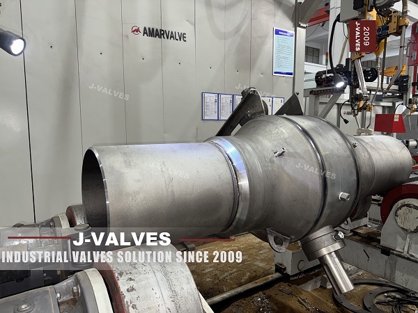
The feature list on this page says one piece body, and the structural section says fully welded. Those two phrases are used as if they meant the same thing, and on a welded valve they do not. A one piece body is machined or forged from a single block of steel and has no seam. A fully welded body is assembled from a pipe section and two ends and has at least two seams, and often four once the transitions are welded on.
This is a two to fifty six inch trunnion valve in a welded shell, rated from Class 150 to Class 2500, with an extended stem for a buried or otherwise remote installation. The body is forged carbon steel, stainless or alloy steel, the ball is hardened stainless or alloy, the ends are butt weld or socket weld, and the drive can be a handwheel, a pneumatic actuator or an electric one.
The seam count is not a detail for inspectors to worry about later. It decides how many radiographs a valve needs, how many field joints a coating crew has to close, and how many locations can fail by fatigue in twenty years. A page that says one piece body is telling a buyer there are none, and that is the claim this page has to correct before anything else.
Design and Construction
The shell is built from a length of forged pipe with a forged end welded to each side. That gives two circumferential seams as a minimum. When the valve needs a transition piece at each end, as it does on a line of a different steel, two more seams are added, and when the extension column is welded rather than bolted on, another one appears at the top.
The ball runs on trunnions in bearings set into the body, the seats sit in pockets at each end, and the stem passes through the top flange into the extended column. The column carries the stem up to the drive, with guide bushings to keep the shaft from bending, and the operating point is at the top where a person can reach it.
Look at the body in the photograph and count the bands. Each one is a weld made in the shop, radiographed before coating, and inaccessible afterwards. That is the whole argument for counting them: a flange can be inspected with a torch and a mirror at any time, and a seam can only be inspected once, at the moment it is made.
The ends are the other interface. On this range they can be butt weld to the ASME profile, socket weld for small sizes, or flanged, and each of those changes what happens at the joint rather than at the body. A socket weld end in particular hides the root of the weld inside the socket, which is why it is limited to small sizes and why radiography is not the usual inspection for it.

Every Ring Weld Is A Future Inspection
A welded body is sold on the absence of leaks. That is a fair claim and it is the reason the design exists, but it comes with a bill that is paid in three currencies: inspection at the factory, coating at the field joint, and the inability to look at the seam again. None of the three is visible on a data sheet, and all three are decided by how many seams the body has.
| Seam | Where It Is | How It Is Proved | What Happens Later |
|---|---|---|---|
| Body to end, left | Between the pipe section and the left end | Radiography before coating | Cannot be seen again without cutting the coating |
| Body to end, right | Between the pipe section and the right end | Radiography before coating | Same |
| Transition to body, each side | Where a pup piece joins the body | Radiography, plus a hardness check if dissimilar | Same, and the dissimilar joint is the one that can crack |
| Column to top flange | Where the extension is attached | Dye penetrant or radiography, depending on the joint | Not a pressure boundary unless the design makes it one |
| Field joint, each end | Where the valve meets the line | To the pipeline specification | The only seam that can be re-inspected, because it is new |
The table is short and it is the whole maintenance argument. Two seams minimum, four with transitions, and every one of them is proved once. A valve with a body flange would have a gasket to renew instead, which is a worse solution for a leak but a better one for an inspection, and that trade is what a buyer is actually making when choosing between the two designs.
The dissimilar seam deserves a sentence of its own. Where a transition in line pipe steel is welded to a body in A105, the joint is between two different materials, and the heat affected zone on the carbon side is where hardness rises. That zone is checked with a hardness survey after welding, and on sour service it is the acceptance criterion that decides whether the valve ships.
Technical Specifications
The table below reproduces the factory data and rewrites three lines. The standard is corrected because API 608 does not reach the top of this range, the actuator line is written to match the operation list rather than the structural text, and the temperature is marked as material dependent rather than given as a fixed span.
| Item | Value |
|---|---|
| Size range | 2 inch to 56 inch, DN 50 to DN 1400 |
| Pressure class | Class 150 to Class 2500, PN 20 to PN 420 |
| Temperature | Minus 46 to plus 200 Celsius, material and seat dependent |
| Body | Forged carbon steel A105, stainless 304 or 316, or alloy steel |
| Body construction | Welded shell, two circumferential seams minimum |
| Ball | Hardened stainless or alloy steel, coated on request |
| Stem | Stainless or alloy steel, extended to the drive |
| Seat | PTFE or RPTFE, or a metal seat for higher temperature |
| Packing | Graphite, wire reinforced |
| Ends | Butt weld to ASME B16.25, socket weld on small sizes, flanged on request |
| Extension | Stem and column to the operating point, with guide bushings |
| Operation | Handwheel, pneumatic, or electric, with a gas over oil option |
| Face to face | ASME B16.10 for the size and class, over the body |
| Design standard | API 6D and ASME B16.34, API 608 within DN 600 and Class 600 |
| Test standard | API 6D and API 598 |
| Fire test | API 607 and ISO 10497, on the design |
| Anti-static | Ball to stem to body continuity |
| Coating | Three layer polyethylene or fusion bonded epoxy, seams coated after test |
Two lines need explaining. The design standard is the one that matters most: API 608 covers steel ball valves to DN 600 and Class 600, and this valve is offered to fifty six inches and Class 2500, so the governing document is API 6D and a 608 certificate above that ceiling describes a valve that does not exist.
The second is the operation line. The structural text on the original page describes a gas hydraulic actuator, while the operation line lists a handwheel, pneumatic and electric. Both cannot be the specification of one valve, and a buyer ordering from the page would not know which drive they were buying. The table above keeps the three that the operation line offers and notes the fourth as an option, which is the honest reading.
Standards and Compliance
The valve is covered by API 6D for its class, test and marking, by ASME B16.34 for its wall, by ASME B16.25 for its ends and by API 607 for its fire behaviour. The seams are covered by the welding procedure and by the radiographic acceptance level named on the order, which is a line that is frequently left blank and then argued about at delivery.
| Document | What It Fixes | What It Does Not Fix |
|---|---|---|
| API 6D | Class, cavity relief, test, marking | The number of seams or the weld procedure |
| ASME B16.34 | Body wall at the class and bore | The pipe section wall, which is chosen separately |
| ASME B16.25 | The weld end profile | The pipe wall at the tie-in |
| ASME IX | Procedure and welder qualification | Whether the procedure matches the steels used |
| ASME B31.3 or B31.8 | The pipeline side of the joint | The valve side |
| API 607 and ISO 10497 | Fire test of the design | The extension, which is outside the test |
| API 598 | Shell and seat test at ambient | The seams, which are tested before assembly is complete |
The gap that catches people is ASME IX. A welding procedure is qualified for a combination of materials, thicknesses and processes, and a procedure written for A105 to A105 does not cover A105 to X70. On a valve with transitions, the shop needs two procedures and two sets of qualified welders, and the paperwork has to say so.
Manufacturing Process
The pipe section is cut to length, the ends are forged and machined, and the bevels are cut before welding so that the root is accessible. The seams are made by submerged arc welding where the geometry allows, which gives a deep clean pass, or by a gas shielded process where it does not. Each seam is welded to a procedure that names the current, the voltage, the travel speed and the interpass temperature.
After welding, the shell is radiographed, and on a dissimilar joint it is also hardness surveyed. Then the body is machined: the bore is finished, the seat pockets are cut, the trunnion bores are line bored, and the top flange is faced and drilled. Machining after welding is deliberate, because the weld distorts the shell and any dimension cut before it would have to be corrected after.
The internals go in through the ends before the last seam is closed, and that ordering is the reason a welded valve cannot be repaired by replacing a part. Once the last seam is made, the ball and the seats are inside for the life of the valve unless the body is cut open. The extension is fitted afterwards, and its column is either welded to the top flange or bolted to it.
The choice between those two is not cosmetic. A welded column becomes part of the assembly that has to be handled, tested and coated as one item, and a column welded slightly out of square puts the drive pad off level, which shows up as a shaft that binds at the top of its travel. A bolted column can be aligned after the body is in place, and it can be removed for transport, at the cost of one more joint that has to be kept tight and dry.

Quality Control and Testing
Every seam is radiographed to the acceptance level on the order, and the films are kept. The shell is then hydrostatically tested at the API 6D pressure for its class, and the seats are tested in both directions with the cavity monitored. On a metal seated valve the seat test is run at low and high pressure, because a metal seat that seals cold may not seal warm.
The extension adds its own checks. The torque is measured at the top coupling rather than at the ball, so the buyer knows what the drive has to deliver; the runout at the top of the shaft is checked with a dial gauge; and the guides are checked for clearance with the stem in place. A long shaft with a tight guide will feel stiff at the top and will be blamed on the valve.
The packing is proved before the valve is buried, and that requires a way to see it. On a valve with a two metre column the gland is not reachable, so the design has to provide a drain or a test point at the bottom of the column. A valve without one has no way to show that the packing holds, and the first indication will be a wet pit.

Applications and Industry Service
The case for this valve is a buried line that has to be isolated without excavation. Transmission pipelines, gathering lines, water injection headers and tank farm transfer lines all bury their valves and all want the operating point at the surface. The welded body removes the flange that would otherwise be the leak in the ground, and the extension removes the need to dig.
The second case is a line where the valve is under a road, a rail crossing or a bund, where access is difficult for reasons other than depth. The extension can be led sideways as well as upwards, within the limits of the shaft and its guides, and the operating point can be placed where a person can stand safely.
The third is a line that runs at a temperature where the packing needs to be away from the body. That is usually described as an extended bonnet rather than an extended stem, and the hardware is the same; what changes is that the length is set by heat transfer rather than by depth, and the two requirements can pull in opposite directions.

Installation, Operation and Maintenance
The valve is welded in, tested, coated and then the extension is fitted and aligned. The column has to be vertical within the tolerance on the drawing, because a leaning column loads the packing and the guides on one side, and the lean is set at the bottom weld rather than at the top stand.
On a buried installation the column is surrounded by a protective sleeve, sealed at the top and open at the bottom so that water drains away from the shaft rather than standing against it. The sleeve is usually supplied loose, which is why it is regularly left off, and a column full of groundwater is the most common reason an extended stem valve becomes impossible to turn.
Maintenance is the packing, the seats through the injection ports, the guides and the drive. The packing is at the bottom of the column and is reached by removing the drive and the coupling; the seats are reached from the body, which on a buried valve means a pit; the guides are reached by lifting the column, which means digging. Everything about the maintenance plan depends on keeping the column dry.
How to Specify and Order
An order for this valve has to state the seams, the extension and the standard. The first is a question of inspection scope, the second of geometry, and the third is a correction, because a valve at the top of this range cannot be certified to API 608.
| Line on the Order | What to Write | Why It Matters |
|---|---|---|
| Seams | How many, where, and the radiographic acceptance level | They are proved once and never again |
| Weld procedures | One for similar joints and one for dissimilar, if transitions are fitted | ASME IX qualifies a combination, not a material |
| Transition steel | The line pipe grade, if pup pieces are welded on | The dissimilar joint is the one that can crack |
| Hardness survey | Whether it is required, and the limit | It is the acceptance criterion on sour service |
| Extension length | The operating height, and what the column passes through | The length is geometry, not preference |
| Column sleeve | Length, diameter, top seal and drain | It decides whether the valve turns in five years |
| Ends | Butt weld or socket weld, and the pipe wall | The bevel follows the pipe |
| Design standard | API 6D, with 608 only inside DN 600 and Class 600 | A certificate outside the scope proves nothing |
| Operation | Handwheel, pneumatic, electric, or gas over oil | The page lists three and describes a fourth |
| Coating at the seams | The system and the field joint standard | The seam is where the coating is weakest |
FAQ
Q: Is a fully welded body a one piece body?
A: No. A one piece body is machined or forged from a single block and has no seam. A fully welded body is assembled from a pipe section and two forged ends, so it has at least two circumferential seams, and four once transition pieces are welded on. The page lists both phrases as features of the same valve, which they are not.
Q: Why does the number of seams matter commercially?
A: Because each seam is inspected once, coated once and can never be inspected again. Two seams mean two radiographs, two coating cut backs and two locations that can fail by fatigue. A valve with a body flange carries a gasket instead, which is a worse answer to a leak and a better one to an inspection, and that is the trade being made.
Q: How many welding procedures does a shop need for this valve?
A: Two, if transition pieces in line pipe steel are fitted. ASME IX qualifies a procedure for a combination of materials, thicknesses and processes, so a procedure written for A105 to A105 does not cover A105 to X70. A shop welding a dissimilar joint without that qualification is relying on a procedure that does not apply to the joint.
Q: Why does the page describe a gas hydraulic actuator when the operation line lists three other drives?
A: Because the structural text and the specification block were written separately. The operation line offers a handwheel, a pneumatic actuator and an electric one, and the structural text describes a gas over oil drive, which is a fourth. A buyer ordering from the page would not know which one they were getting, so the drive has to be named on the order.
Q: Can the packing be checked after the valve is buried?
A: Only if the design gives a way to see it. On a two metre column the gland is not reachable, so a drain or a test point at the bottom of the column is the only means of proving it. Without one, the first indication of a weeping gland is water in the pit, and by then the packing has to be reached by digging.



Hot Products


News
A Ball Valve Is A Tuning Fork: Vibration, Fretting And The Joints That Only Hold By Friction
A ball valve holds seat, stem and body joint by preload alone. Vibration turns that preload into micro-motion, and the wear arrives with no cycle at all.
Read More
Urea Plant Ball Valves: The Wetted Path Survives Only While Oxygen Is Being Fed To It
Carbamate at 150 bar and 185 C eats stainless 50 times faster once the passive film starves. The valve cavity is where the oxygen runs out first.
Read More
Stiction: What A Ball Valve Becomes When Nobody Turns It
A valve that stood closed for years has not worn out. The seat has bonded to the ball, and the first stroke is a step, not a ramp. What the trace shows.
Read More
Molten Salt Ball Valves: The Valve Works at 565 C And Dies at 219 C
Salt freezes at 220 C and decomposes at 565 C. Everything a molten salt ball valve does happens in that 345 kelvin gap, and the gap is not generous.
Read More