


CHINA J-VALVES Offers Various High-quality I ndustrial Ball Valves
J-VALVES, a distinguished professional ball valve manufacturer rooted in China, takes pride in its extensive product portfolio. Our offerings span a wide range, including trunnion-mounted ball valves, floating ball valves, high-temperature ball valves, high-pressure ball valves, metal-sealed ball valves, ultra-low temperature ball valves, DBB ball valves, Three-way And Four-way Ball Valve, and fully welded ball valves. Each product is a testament to our commitment to precision engineering and reliable performance. Meticulously crafted, they are designed to not only meet but exceed the most stringent industrial demands, ensuring stable operation even under extreme conditions. This enables us to provide our clients with high-value services and makes our valves widely sought-after in industries.
Product Category
Contact Us

-
J-VALVES-Q99367F
-
J-VALVES
Overview of the J-VALVES twelve inch class 300 electric welded ball valve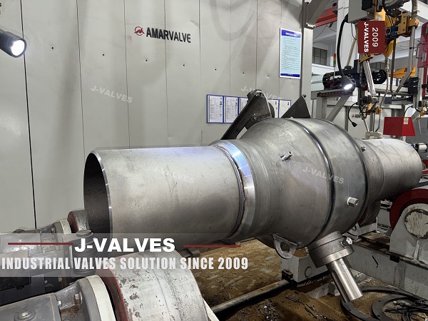
Twelve inches, class 300, electric, welded. Four words and each one narrows the valve a little more, and none of them is the one that decides whether the valve fits the line. That decision belongs to a dimension that is not on this data sheet at all: the wall thickness of the pipe it will be welded to, and the bevel that has to match it.
This is a DN 300 valve in a welded carbon steel body, rated Class 300 which is PN 50 in the API 6D list, with an electric actuator on the top flange, a trunnion mounted ball and butt weld ends. The body is A105N forging or A216 WCB casting, the ball is carbon steel with a nickel or chrome coating or stainless in CF8 and CF8M, and the seat is a polymer or a hardfaced metal ring depending on the temperature.
The page it replaces describes all of that correctly and then puts a two or three piece body in the feature list, which this valve is not. So the work here is to state the construction once, properly, and then spend the rest of the page on the two things a twelve inch welded valve actually gets wrong at site: the bevel and the pipe wall, and the setting of a drive that nobody can reach by hand.
Design and Construction
The shell is a welded body: a pipe section with two ends, joined by circumferential seams, with the ball and seats inserted before the last seam is closed. There is no body flange, no bonnet joint and no cover. The stem leaves through the top flange in a bore above the ball, and the actuator bolts to a pad machined on top of that flange.
The ball is carried on an upper and a lower trunnion. At twelve inches the pressure load on the ball is large enough that a floating design would press the ball into the downstream seat with a force the seat cannot survive, which is why this size is trunnion mounted as a matter of course. The seats sit in pockets at each end of the body and are spring loaded, with line pressure adding to the spring force once the valve is in service.
The photograph is worth reading for what is missing. No flange bolt circle, so the valve cannot be unbolted and rotated to suit a misaligned pipe. No bonnet, so the packing can only be reached from above. No visible body joint, so the seats can only be reached through the injection ports. A twelve inch valve with those three restrictions has to be right the first time, and that is the argument for spending the page on dimensions rather than on features.
The coating line matters more on this valve than on a flanged one. A welded end is masked and left bare for the field joint, and the mask line is where the coating ends. On a twelve inch body the bare ring is a wide band of unprotected steel that has to survive transport, storage and the wait for the tie-in, and it is the first place rust appears on a valve that has not been installed yet.

The Bevel Follows The Pipe, Not The Class
A valve body is dimensioned by its class. ASME B16.34 gives the wall for a Class 300 body at a given bore, and that wall is thick because it has to hold the shell test pressure with a margin. A pipe is dimensioned by its schedule. ASME B36.10 gives the wall for a twelve inch pipe in STD, SCH 40, SCH 60, SCH 80 and heavier, and those walls are not the same as the valve's wall, not even close at Class 300.
| Source | What It Fixes | What It Does Not Know |
|---|---|---|
| ASME B16.34 | The wall of the valve body at its class and bore | The pipe it will be welded to |
| ASME B36.10 | The wall of the pipe at its nominal size and schedule | The valve it will meet |
| ASME B16.25 | The bevel profile, with its root face and angle | Which of the two walls it is cut into |
| The purchase order | Which wall the bevel is cut for | Everything above, unless it is written down |
The consequence is a joint between two different wall thicknesses, and there are only two honest ways to make it. One is to machine the valve end to the pipe wall, so that the bore is continuous and the bevel is cut into a wall that matches. The other is to leave the valve end at full thickness and transition inside the bore, which is a machining operation on the valve and has to be drawn. What cannot be done is to weld a thick end to a thin pipe and let the welder fill the step.
If that step is left on the inside, it becomes a ledge in the flow path. On a line carrying solids it collects them; on a line carrying a corrosive product it is where the flow separates and where the corrosion starts. On the outside it is worse, because a thick-to-thin joint concentrates stress at the toe of the weld and that is where a fatigue crack begins on a line that cycles.
The same logic applies to the bevel profile itself. ASME B16.25 defines one geometry and EN 12627 defines another, and a valve machined to one will not close up properly against a pipe prepared to the other. Since this valve has butt weld ends by definition, the profile is not an accessory: it is the interface, and the order has to name it along with the pipe wall.
Technical Specifications
The table below is the factory data for this size, with the construction line corrected and the seat temperature split out. The class, the bore and the body materials are as published, and the PN equivalent of Class 300 is 50, which is one of the seven codes API 6D actually lists rather than a number derived from a pressure conversion.
| Item | Value |
|---|---|
| Nominal size | 12 inch, DN 300 |
| Pressure class | Class 300, PN 50 |
| Temperature | Minus 29 to plus 425 Celsius, carbon steel body |
| Body | ASTM A105N forged or A216 WCB cast, welded shell |
| Ball | A105N or WCB with ENP or hard chrome, or CF8 and CF8M |
| Trunnion | Upper and lower, in body steel |
| Stem | A182 F316 or 17-4PH |
| Seat | PTFE or RPTFE to 180 Celsius, PPL to 260, metal on request |
| Seat design | Spring loaded, single piston effect standard |
| Packing | Flexible graphite, braided with wire reinforcement |
| End connection | Butt weld to ASME B16.25, profile named on the order |
| Face to face | ASME B16.10 for 12 inch Class 300, over the body |
| Operation | Electric, on-off or modulating, manual override fitted |
| Actuator supply | Three phase or single phase, 380 V, 220 V or 24 V, DC available |
| Design standard | API 6D and ASME B16.34 |
| Test standard | API 6D and API 598 |
| Fire test | API 607 and ISO 10497, on the design |
| Coating | Three layer polyethylene or fusion bonded epoxy, ends masked |
Two lines deserve a note. The face to face value is taken from B16.10 at twelve inches and Class 300, measured over the body and not over the weld ends, so the overall length is longer than the table figure and the pipe cut has to allow for it. The actuator supply line is written as a range because the page offers several voltages; a three phase motor on the wrong rotation drives the valve the wrong way, and on a welded valve there is no flange to unbolt while it is sorted out.
Standards and Compliance
Five documents cover this valve and only one of them has anything to say about the pipe. That is the structural reason a twelve inch welded valve goes wrong: the valve is proved against its own standards, the pipe is proved against its own, and the joint between them is proved against a procedure that somebody has to write. If the procedure is written for the wrong wall, both components can be perfect and the joint still fails.
| Document | What It Fixes | What It Leaves To The Order |
|---|---|---|
| API 6D | Class, cavity relief, test, marking | The bevel and the pipe wall |
| ASME B16.34 | Body wall at Class 300 | The pipe schedule |
| ASME B16.25 | The bevel geometry | Which profile, B16.25 or EN 12627 |
| API 598 | Shell and seat test at ambient | The seat behaviour at 425 Celsius |
| API 607 | Fire test of the design | Whether the actuator is included |
| ASME IX | Welder and procedure qualification | Whether the procedure was written for this joint |
The fire test line is the one that catches actuated valves. API 607 is a test of a valve design, and the certificate that comes out of it is for the valve without an actuator unless the actuator was on it during the test. An electric actuator has a motor, a gearbox and a set of seals that are not designed for a fire, and the valve may pass the test while the drive does not survive it. If the fire case is real, that has to be asked as a question about the assembly rather than about the valve.
Manufacturing Process
The body starts as a forging or a casting, is rough machined, and is then bored and faced. The seat pockets are cut to take either a polymer seat or a metal ring, and the trunnion bores are line bored so the two bearings are concentric. The stem bore is drilled through the top flange and honed, and the stuffing box is machined above it with a shoulder for the packing and a thread or a bolted gland above that.
The internals go in through the ends. Ball first, then the seats in their pockets, then the trunnions and their bearings, and then the end pieces are drawn up and welded. The seams are made by submerged arc or by a gas shielded process, and each is radiographed after cooling. On a twelve inch body the seam is long enough that a single pass is not practical, which is why the procedure specifies the number of passes and the interpass temperature rather than just the process.
The weld ends are finished after the shell is closed. That ordering is deliberate: the bevel is the dimension that has to match the pipe, so it is cut last, gauged, and protected. On a coated valve the bevel and a length behind it are masked, and the mask line is measured from the bevel face so that the field joint has the length it needs.

Quality Control and Testing
The shell is hydrostatically tested at the Class 300 pressure required by API 6D, and the seats are tested in both directions with the cavity monitored. A twelve inch soft seated valve is also checked for seat leakage at low pressure, because a seat that seals at full pressure and weeps at a few bar is a seat with a damaged sealing edge, and the damage is usually handling rather than design.
The weld ends are gauged for bevel angle, root face and wall, and the bore is checked for ovality after welding. That last check is the one that finds a seam that pulled the body out of round, and it is done before the coating because a body that has to be re-machined cannot be re-machined through three layers of polyethylene.
The actuator is tested as an assembly. Travel is run from stop to stop, the limit switches are set against the mechanical stop rather than against a nominal ninety degrees, the torque switch is set above the measured running torque, and the feedback contacts are proved at both ends. On this valve the torque switch setting matters more than usual, because a twelve inch ball at Class 300 differential has a running torque that is a real number and a seat that will not forgive an overwound end stop.

Applications and Industry Service
Twelve inch Class 300 is the size and class of a great many station valves. Metering runs, regulator inlet isolation, compressor suction and discharge, tank farm headers and water injection lines all use it, because it is the largest size that is still routinely handled as a single piece and the lowest class that covers the pressures those systems run at.
The electric drive is chosen on those same stations for a practical reason: the valve is usually within reach of the station power and rarely within reach of an instrument air header. An electric actuator on a welded body also removes the pneumatic tubing, which on a buried or congested station is one more thing to protect and one more thing to leak.
The welded body is chosen where the station is congested and a flange leak would be a fire. That is the same argument as everywhere else on this site, and at twelve inches it has a specific form: the flange that is removed is a twelve inch Class 300 flange, which is a large joint with a large gasket and a large number of studs, and each of those studs is a place where a fitter can be wrong.

Installation, Operation and Maintenance
The valve arrives with bare ends, a masked coating line and an actuator that has been set on a bench. The first site task is to check the pipe: measure the wall, confirm the schedule, and compare it with the bevel on the valve. If they do not match, the valve end is machined before the weld, not after, because after the weld the only remedy is to cut it out.
Welding follows the qualified procedure, with the heat input controlled and the body temperature checked during the pass, since the seat is a polymer item a short distance from the seam. After the weld, the joint is inspected to the level the line specification asks for, coated, and holiday tested. Then the valve is stroked once with the line at pressure if the procedure allows, and the position feedback is checked against the mechanical indicator.
Operation is by the actuator, with the handwheel kept for the case where the supply is lost. The handwheel is a mechanical clutch type, which means somebody has to go to the valve and engage it, and on a station valve that is a planned response rather than an emergency one. Maintenance is the packing from above, the seats through the injection ports, the cavity through the drain, and the actuator as a unit; there is no fifth item, and the ball cannot be replaced without cutting the body out.
How to Specify and Order
Four lines on the order decide whether this valve works: the bevel profile, the pipe wall, the fail position of the drive, and the fire case as an assembly. The rest is standard. A twelve inch welded valve ordered without those four is a valve that will be argued about at the trench, at the panel, or after the first inspection.
| Line on the Order | What to Write | Why It Matters |
|---|---|---|
| Bevel profile | ASME B16.25 or EN 12627, named | The profiles do not interchange |
| Pipe wall | The schedule and the measured wall at the tie-in | The bevel is cut to the pipe, not to the class |
| Overall length | B16.10 plus the weld end length | The table value is over the body only |
| Seat | Polymer grade, or metal, with the temperature | Decides torque and the top of the range |
| Actuator supply | Voltage, phase, rotation, cable entry | Wrong rotation drives the valve the wrong way |
| Fail position | Fail last, spring return, or back-up | It cannot be corrected after the weld |
| Torque switch | Set against the measured running torque | The only protection against an overwound stop |
| Fire case | Whether the actuator is in the test scope | API 607 covers the valve, not the drive |
| Radiography | Extent and acceptance level | Seams are invisible after coating |
| Masking at the ends | The length left bare for the field joint | It is where corrosion starts |
FAQ
Q: Why does the bevel matter more than the class on a welded valve?
A: Because the class decides the valve's wall and the pipe schedule decides the pipe's wall, and they are not the same number. The bevel has to be cut to the wall it will actually meet. If the two do not match and nobody machines a transition, the joint has either a step on the inside, which traps product and starts corrosion, or a step on the outside, where stress concentrates at the weld toe.
Q: Is class 300 the same as PN 50?
A: Yes, in the API 6D list of pressure designations, which pairs Class 300 with PN 50. The other codes are PN 20, 64, 100, 150, 250 and 420, and between them they cover Class 150 to Class 2500. A number that is not on that list, such as PN 16 or PN 26, does not belong in a valve specification written to 6D.
Q: Does the twenty or twenty five piece body mentioned in the features apply here?
A: No. This is a fully welded body: a pipe section with two ends joined by circumferential seams, and no body joint that opens. The feature list on the original page is shared with the three piece products on the same site, which is why it mentions a two or three piece body on a page about a welded one. The construction section of this page describes the valve that is actually in the photograph.
Q: What happens if the actuator is wired for the wrong rotation?
A: The motor drives the valve the wrong way, the limit switches do not stop it at the intended end, and the torque switch becomes the only thing that stops it. On a flanged valve this is an inconvenience; on a welded valve there is no flange to unbolt while it is sorted out, so the phase rotation is checked before the drive is commissioned rather than after.
Q: Is the fire certificate valid with the actuator fitted?
A: Only if the actuator was on the valve during the test. API 607 is a test of a design, and the certificate normally covers the valve without a drive. A motor, a gearbox and their seals are not designed for a fire, so the assembly may not survive what the valve survives. Ask for the test scope rather than for the certificate.


Hot Products


News
A Ball Valve Is A Tuning Fork: Vibration, Fretting And The Joints That Only Hold By Friction
A ball valve holds seat, stem and body joint by preload alone. Vibration turns that preload into micro-motion, and the wear arrives with no cycle at all.
Read More
Urea Plant Ball Valves: The Wetted Path Survives Only While Oxygen Is Being Fed To It
Carbamate at 150 bar and 185 C eats stainless 50 times faster once the passive film starves. The valve cavity is where the oxygen runs out first.
Read More
Stiction: What A Ball Valve Becomes When Nobody Turns It
A valve that stood closed for years has not worn out. The seat has bonded to the ball, and the first stroke is a step, not a ramp. What the trace shows.
Read More
Molten Salt Ball Valves: The Valve Works at 565 C And Dies at 219 C
Salt freezes at 220 C and decomposes at 565 C. Everything a molten salt ball valve does happens in that 345 kelvin gap, and the gap is not generous.
Read More