


CHINA J-VALVES Offers Various High-quality I ndustrial Ball Valves
J-VALVES, a distinguished professional ball valve manufacturer rooted in China, takes pride in its extensive product portfolio. Our offerings span a wide range, including trunnion-mounted ball valves, floating ball valves, high-temperature ball valves, high-pressure ball valves, metal-sealed ball valves, ultra-low temperature ball valves, DBB ball valves, Three-way And Four-way Ball Valve, and fully welded ball valves. Each product is a testament to our commitment to precision engineering and reliable performance. Meticulously crafted, they are designed to not only meet but exceed the most stringent industrial demands, ensuring stable operation even under extreme conditions. This enables us to provide our clients with high-value services and makes our valves widely sought-after in industries.
Product Category
Contact Us

-
J-VALVES-Q967F
-
J-VALVES
Overview of the J-VALVES electric trunnion mounted fully welded ball valve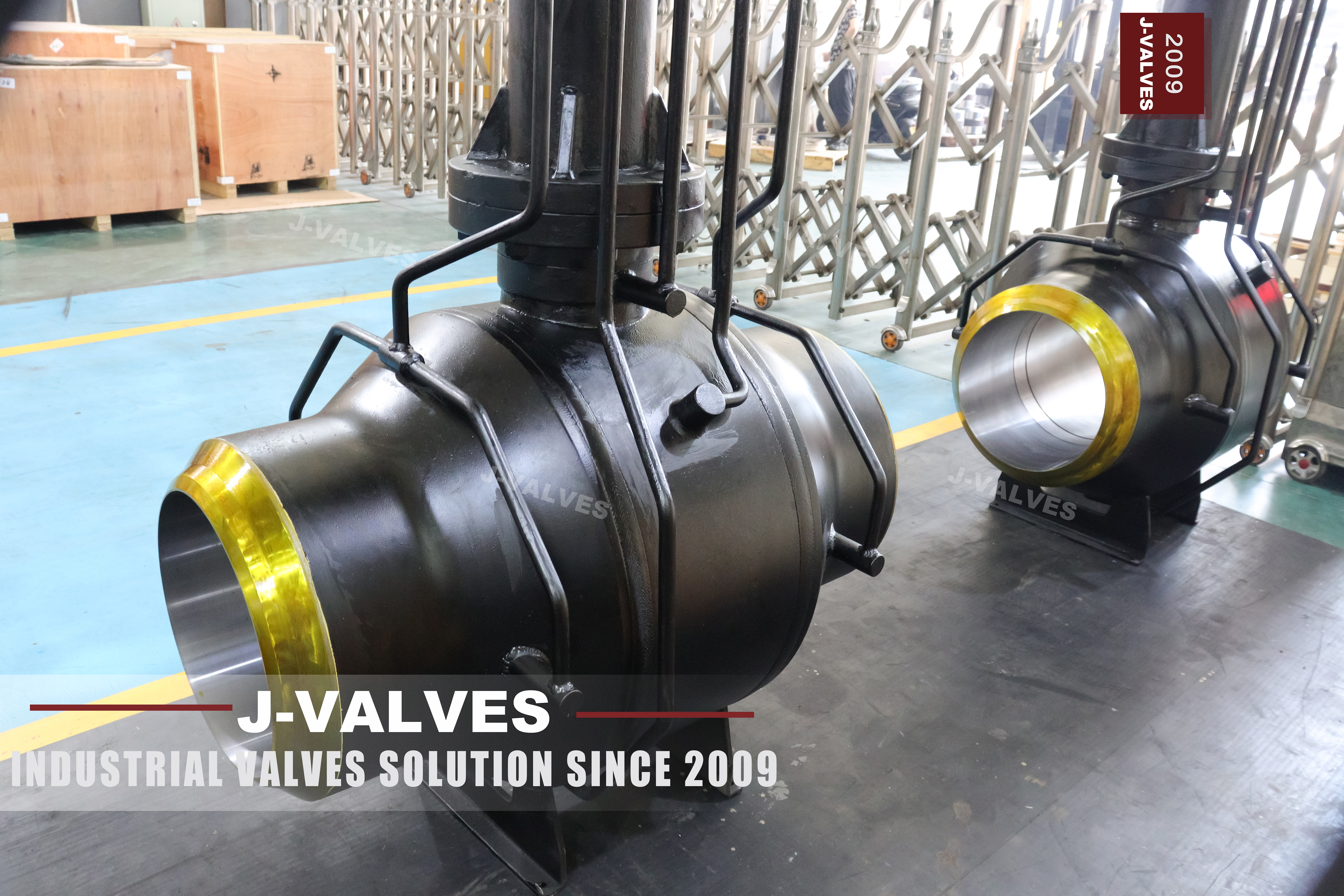
An electric actuator on a ball valve is usually chosen for one of three reasons: the line is far from an air supply, the operator wants position feedback in the control room, or the valve has to move on a schedule that nobody wants to walk to. All three are good reasons. None of them changes what the valve does when the power fails, and that is the first thing this page has to say, because on a welded body the answer is not obvious from the outside.
This is a two to fifty six inch trunnion valve in a welded shell, rated from Class 150 to Class 2500, with an electric actuator on the top flange and no body joint anywhere. The ball is carried on an upper and a lower trunnion, the seats are single or double piston effect, the stem leaves through graphite packing, and the ends are butt weld or socket weld with flanged ends as an option.
The page that this one replaces describes that valve in the language of a catalogue: reliable, compact, low torque, maintenance free. All of it is true in the sense that it is true of every welded trunnion valve made anywhere. What it does not say is what an electric actuator does to the maintenance plan of a valve that cannot be opened, and that is the part a buyer actually has to decide before the order.
Design and Construction
The shell is welded from a forged pipe section and two forged ends, with circumferential seams and no body flange. Because there is no cover to lift, everything that wears has to be reachable from outside: the stem packing through the top flange, the seats through the injection ports, the cavity through the drain. Those four openings are the whole maintenance surface of the valve, and each of them is a penetration of the pressure boundary.
The ball sits on two trunnions in bearings pressed into the body. The pressure load on the ball goes into those bearings rather than into the seats, which is why a trunnion valve turns with a fraction of the torque a floating valve of the same size needs. That low torque is what makes a small electric actuator possible on a large valve, and it is also what makes the torque switch setting matter, because the margin between running torque and damaging torque is narrower than it looks.
Read the photograph as a list of interfaces rather than as a product shot. There is one mechanical interface, the actuator pad; one electrical interface, the cable entry; two weld ends; and the injection and drain ports at the body. Every one of them is a place where the valve can be got at, and there is no fifth. A valve with a bolted body would offer a cover as well, and the absence of that cover is the whole commercial argument for this design.
The seats are the part that decides what the valve can do in a fire and what it can do when the cavity fills with liquid. A single piston effect seat lets the cavity pressure push the seat away from the ball and relieve into the upstream side; a double piston effect seat does not, and holds pressure from both directions. Combined seats do one thing upstream and the other downstream. The table below is the one the factory publishes, and it is the only place where the trade is stated plainly.
| Seat Design | Bi-directional Sealing | Body Cavity Self Relieving | Double Barrier |
|---|---|---|---|
| Single piston effect, SPE | Yes | Yes | No |
| Double piston effect, DPE, DIB 1 | Yes | No | Yes |
| Combined, DIB 2 | Yes | Yes | Yes, preferred direction only |
The consequence is easy to state and easy to get wrong. A DPE seat gives two barriers in series and a cavity that cannot vent itself, so any thermal expansion of trapped liquid has to go somewhere, and the somewhere is a relief line or the seat. An SPE seat vents but gives one barrier. Choosing between them is a decision about the cavity, not about the ball, and the actuator has nothing to do with it.

The Motor Holds Its Position, The Valve Cannot
An electric actuator with no spring return does not fail closed and does not fail open. It fails where it was. The motor stops, the gear train holds, and the valve stays at whatever opening it had when the supply disappeared. That behaviour is called fail last, and for a lot of process valves it is exactly right, because a valve that slams shut on a power dip can break a line. For an emergency shutdown valve it is exactly wrong, and the difference has to be written on the order rather than assumed.
On a flanged valve a wrong fail position can be corrected later by changing the actuator, which is an afternoon and a crane. On this valve the actuator is still changeable, because it sits on a pad and bolts down, but the valve underneath is welded into the line. If the fail position matters, it has to be right at the factory, and the factory needs to know which one is wanted: fail last, fail close with a spring, or fail close on a battery and a stored charge.
The second decision is the torque switch. A limit switch stops the actuator at the end of travel, and a torque switch stops it when the resistance rises above a set value. They are not the same device and they do not protect the same thing. The limit switch protects the end stop; the torque switch protects the gear train, the stem and the seat from an obstruction that the limit switch cannot see. On a valve that cannot be opened for inspection, the torque switch is the only protection against a half-seated ball being forced.
The third is the word modulating. The specification on this page offers on-off, modulating and intelligent control, and the first two are not interchangeable on a ball valve. A quarter turn ball valve is an isolating device: at part open the flow passes a narrow crescent between the ball and the seat at high velocity, and on a soft seat that crescent is the first thing to wear. Modulating service on a ball valve is possible, but it is a decision that changes the seat material, the actuator duty and the maintenance interval, and it should not be read off a list of options.
Technical Specifications
The table below is the factory data for this valve, with two lines corrected where the original page overstates the scope. The class range and the size range are as published. What is corrected is the design standard, because API 608 does not reach either end of this range, and the temperature line, because minus 29 Celsius is a property of the carbon steel body and not of the seats.
| Item | Value |
|---|---|
| Size range | 2 inch to 56 inch, DN 50 to DN 1400 |
| Pressure class | Class 150 to Class 2500, PN 20 to PN 420 |
| Temperature | Minus 29 to plus 425 Celsius, carbon steel body |
| Body | ASTM A105 forged carbon steel, welded shell |
| Body options | A350 LF2 to minus 46, A182 F304 or F316, F51 or F53 duplex |
| Ball | A182 F304 or F316, F51 or F53, ENP or tungsten carbide coating |
| Trunnion | Surface hardened, in body steel or 17-4PH |
| Stem | A182 F304 or F316, 17-4PH |
| Seat | PTFE or RPTFE to 180 Celsius, PEEK to 260, metal with graphite to 425 |
| Seat design | SPE standard, DPE and combined on request |
| Packing | Graphite, wire reinforced, live loaded on request |
| Ends | Butt weld to ASME B16.25, socket weld, flanged on request |
| Actuator | Electric, on-off or modulating, 380 V, 220 V or 24 V, DC available |
| Feedback | Open, closed and fault contacts, 4 to 20 mA position transmitter optional |
| Override | Handwheel or crank, mechanical clutch |
| Design standard | API 6D and ASME B16.34, API 608 within DN 600 and Class 600 |
| Test standard | API 6D and API 598 |
| Coating | Three layer polyethylene or fusion bonded epoxy |
Two of those lines are worth an argument. API 608 is a standard for steel ball valves up to DN 600 and Class 600, and this page offers a valve to DN 1400 and Class 2500; above that ceiling the governing document is API 6D, and a certificate quoting 608 for a 36 inch Class 900 valve is a certificate for something that does not exist. The second is the temperature. A single range of minus 29 to plus 425 is a range of the body steel with a metal seat; RPTFE stops long before 425, and a buyer who reads the top line as the valve's range will order a soft seated valve for a hot line.
Standards and Compliance
Four documents do most of the work on this valve, and none of them covers the actuator. That split is the reason a welded valve with an electric drive is usually bought as two certificates rather than one. The valve is proved against API 6D and API 598; the actuator is proved against its own enclosure and hazardous area standards, and the two sets of papers do not refer to each other.
| Document | What It Fixes | What It Leaves Open |
|---|---|---|
| API 6D | Classes, cavity relief, test pressures, marking | The actuator, which is an accessory |
| ASME B16.34 | Wall thickness and pressure temperature ratings | The weld procedure for the shell |
| API 598 | Shell test and seat test at ambient | The seat behaviour at the top of the temperature range |
| ASME B16.25 | The weld end profile | The pipe wall it will be joined to |
| API 607 and ISO 10497 | Fire test of the design | Whether the actuator survives the same fire |
| IEC 60529 | The enclosure index of the actuator | The valve, which has no enclosure |
| IEC 60079 | The hazardous area certification of the drive | The process, which may be the reason for it |
The line that catches people is the fire test. API 607 proves a design: a valve of that design was burnt and then pressure tested, and the result is a certificate for the design, not for the unit in the crate. An actuator mounted on a fire tested valve has not been fire tested with it unless the actuator supplier has done the work, and most have not. If the fire case matters, the spring return and the mounting have to be part of the same conversation.
Manufacturing Process
The shell starts as a forged pipe section and two forged ends. The ends are machined with the weld bevel before welding, because a bevel cut after welding cannot be inspected from the inside. The circumferential seams are made by submerged arc welding or by a gas shielded process, and each seam is radiographed once it has cooled and before any coating or paint goes near it.
The ball is machined, ground and then coated. ENP is an electroless nickel deposit, hard chrome is electroplated, and tungsten carbide is applied by high velocity spraying; all three are surface treatments on a steel ball, and all three change the seat clearance, which is why the ball is coated before the seats are matched to it. The trunnion journals are ground after hardening, and the bearings are pressed into the body.
Assembly is the part that cannot be undone. The ball, the seats and the trunnions go in through the end openings before the ends are welded on, so the order of operations is fixed: internals first, then the end welds, then the radiography, then the pressure test, then the coating. A mistake found after the end welds is not a repair, it is a cut and a re-weld, which is the subject of the page on repairing a welded body.
The actuator is fitted last. Its pad is machined flat and drilled to the mounting pattern, the stem adaptor is keyed or squared to the valve stem, and the limit switches are set against the actual travel of that ball rather than against a nominal ninety degrees. That setting is done with the valve on the test bench, because after installation the only way to check it is to run the valve and watch the feedback.

Quality Control and Testing
Every shell is hydrostatically tested at the pressure API 6D requires for its class, and every seat is tested at both low and high pressure. The seat test is done in both directions, which on a DPE seat means two separate tests with the cavity monitored, because a DPE seat that leaks into the cavity will pass a single direction test and fail in service.
The electrical side has its own tests, and they are usually the ones left out of a purchase order. The actuator is run from fully open to fully closed and back, the limit switches are set and then checked against the mechanical stop, the torque switch is set above the measured running torque, and the feedback contacts are proved at both ends. On an intelligent actuator there is a fifth item, the communication link, and a sixth, the record of the settings, because a configuration that is not recorded cannot be restored after a board failure.
The one test that is often missing is the anti-static continuity check, and on a valve with polymer seated bearings it is the one that decides whether the ball is bonded to the body. A soft seated ball on PTFE bearings is insulated from the shell by the very parts that make it turn easily, and a static charge built up on the ball has nowhere to go until it arcs across a seat. The check is a resistance measurement between ball, stem and body, and it is worth having the number on the test sheet rather than a tick in a box.

Applications and Industry Service
The natural home for this valve is a line that has no air and does not want a compressor. Gas transmission laterals, tank farm manifolds, water injection headers and long distance slurry lines all share the same shape of problem: the valves are far apart, the duty is open or closed, and the only power available is a cable that is already there for the pump or the meter. An electric actuator on a welded trunnion valve fits that description without modification.
The second home is a line that has to report. A position transmitter and a pair of fault contacts let a control room know whether a valve is where it was told to be, and on a buried line that report is the only evidence anyone has. This is where the intelligent actuator earns its price: not by turning the valve, which any actuator can do, but by keeping a record of how much torque the last stroke took, which is a proxy for how much the seat has worn.

Installation, Operation and Maintenance
The valve is welded in, so the installation plan and the maintenance plan are the same document. Before the weld, the ends are aligned and the gap is set to the bevel; during the weld, the body is protected from the heat, and on a soft seated valve that means a heat sink or a wet rag on the body and a thermocouple on the shell. After the weld, the seam is inspected and coated, and the valve is stroked once to prove that nothing moved.
The actuator needs three things at commissioning that the valve does not. It needs the correct supply voltage and phase rotation, because a three phase motor wired backwards drives the valve the wrong way and the limit switches will not stop it. It needs the torque switch set against the measured running torque rather than the factory default, because the default is chosen for a catalogue valve and not for this one. And it needs the position feedback calibrated at both ends, because a 4 to 20 mA transmitter that was set on the bench will drift by the time the valve is at temperature.
Maintenance on the valve side is limited to four items: the packing, the seats through the injection ports, the cavity through the drain, and the actuator itself. There is no fifth. Packing is replaced by removing the yoke and the gland, which can be done in line; seats are recharged with sealant through the injection ports, which restores a seal but does not restore a worn seat; and the cavity is vented through the drain before any of it. A valve that will not seal after injection needs to be cut out, and that decision belongs in the maintenance procedure rather than in the emergency response.
How to Specify and Order
An order for this valve has to settle four things that the catalogue page leaves open: the fail position, the control mode, the seat design and the standard. The first three are choices about the duty. The fourth is a correction, because a valve offered to Class 2500 in a size above DN 600 cannot be certified to API 608 and should be ordered to API 6D.
| Line on the Order | What to Write | Why It Matters |
|---|---|---|
| Fail position | Fail last, spring return close, or battery back-up | The valve cannot be corrected after it is welded in |
| Control mode | On-off, or modulating with the duty cycle stated | Modulating changes the seat, the actuator and the interval |
| Seat design | SPE, DPE or combined, with the cavity plan | Decides whether the cavity can vent itself |
| Actuator supply | Voltage, phase, and the cable entry size | A three phase motor on the wrong rotation will not stop at the limit |
| Feedback | Contacts, 4 to 20 mA, or a protocol | Decides what the control room can see |
| Design standard | API 6D, with 608 only inside DN 600 and Class 600 | A certificate to the wrong standard is not a certificate |
| Ends | Butt weld to B16.25 or socket weld, with the pipe wall | The bevel follows the pipe, not the valve class |
| Radiography | The extent and the acceptance level | The seams cannot be inspected after coating |
| Coating and cut back | System, thickness, and the length left bare | The bare ring is where corrosion starts |
| Anti-static | The measurement points and the recorded value | It is the only proof the ball is bonded |
FAQ
Q: What does an electric actuator do when the power fails?
A: Unless a spring return or a battery back-up is ordered, it holds the valve where it was. The motor stops, the gear train holds the load and the ball stays at its last opening. That is called fail last, and it is a deliberate behaviour rather than a fault, but it has to be asked for, because the alternative is not something that can be added to a welded valve later.
Q: Can the fail position be changed after the valve is installed?
A: The actuator can be unbolted from the pad and replaced, so the drive is changeable. What cannot be changed is the valve, which is welded into the line. If the fail case matters, the decision has to be made before the shell is welded, and the order has to say which of the three behaviours is wanted.
Q: What is the difference between a limit switch and a torque switch?
A: A limit switch stops the actuator at the end of travel, so it protects the end stop. A torque switch stops it when the resistance rises above a set value, so it protects the gear train, the stem and the seat from an obstruction in mid travel. A valve can be at neither end and still be overloaded, which is the case the limit switch cannot see.
Q: Is a modulating electric actuator suitable for a ball valve?
A: Only if the seat and the duty are chosen for it. A quarter turn ball valve is an isolating device: at part open the flow passes a narrow crescent at high velocity, and on a soft seat that crescent wears first. Modulating service changes the seat material, the actuator duty cycle and the maintenance interval, so it belongs in the specification rather than on a list of options.
Q: Why does the page quote API 608 for a valve up to fifty six inches?
A: It should not. API 608 covers steel ball valves to DN 600 and Class 600, and this range runs to DN 1400 and Class 2500. Above that ceiling the governing document is API 6D, and a certificate to 608 for a large valve describes a valve that does not exist. The class range is genuine; the standard quoted for it is not.


Hot Products


News
A Ball Valve Is A Tuning Fork: Vibration, Fretting And The Joints That Only Hold By Friction
A ball valve holds seat, stem and body joint by preload alone. Vibration turns that preload into micro-motion, and the wear arrives with no cycle at all.
Read More
Urea Plant Ball Valves: The Wetted Path Survives Only While Oxygen Is Being Fed To It
Carbamate at 150 bar and 185 C eats stainless 50 times faster once the passive film starves. The valve cavity is where the oxygen runs out first.
Read More
Stiction: What A Ball Valve Becomes When Nobody Turns It
A valve that stood closed for years has not worn out. The seat has bonded to the ball, and the first stroke is a step, not a ramp. What the trace shows.
Read More
Molten Salt Ball Valves: The Valve Works at 565 C And Dies at 219 C
Salt freezes at 220 C and decomposes at 565 C. Everything a molten salt ball valve does happens in that 345 kelvin gap, and the gap is not generous.
Read More