CHINA J-VALVES Offers Various High-quality I ndustrial Ball Valves
J-VALVES, a distinguished professional ball valve manufacturer rooted in China, takes pride in its extensive product portfolio. Our offerings span a wide range, including trunnion-mounted ball valves, floating ball valves, high-temperature ball valves, high-pressure ball valves, metal-sealed ball valves, ultra-low temperature ball valves, DBB ball valves, Three-way And Four-way Ball Valve, and fully welded ball valves. Each product is a testament to our commitment to precision engineering and reliable performance. Meticulously crafted, they are designed to not only meet but exceed the most stringent industrial demands, ensuring stable operation even under extreme conditions. This enables us to provide our clients with high-value services and makes our valves widely sought-after in industries.
Product Category
Contact Us

-
J-VALVES-Q41F
-
MSNL
Overview of the J-VALVES JIS CF8/CF8M floating flanged ball valve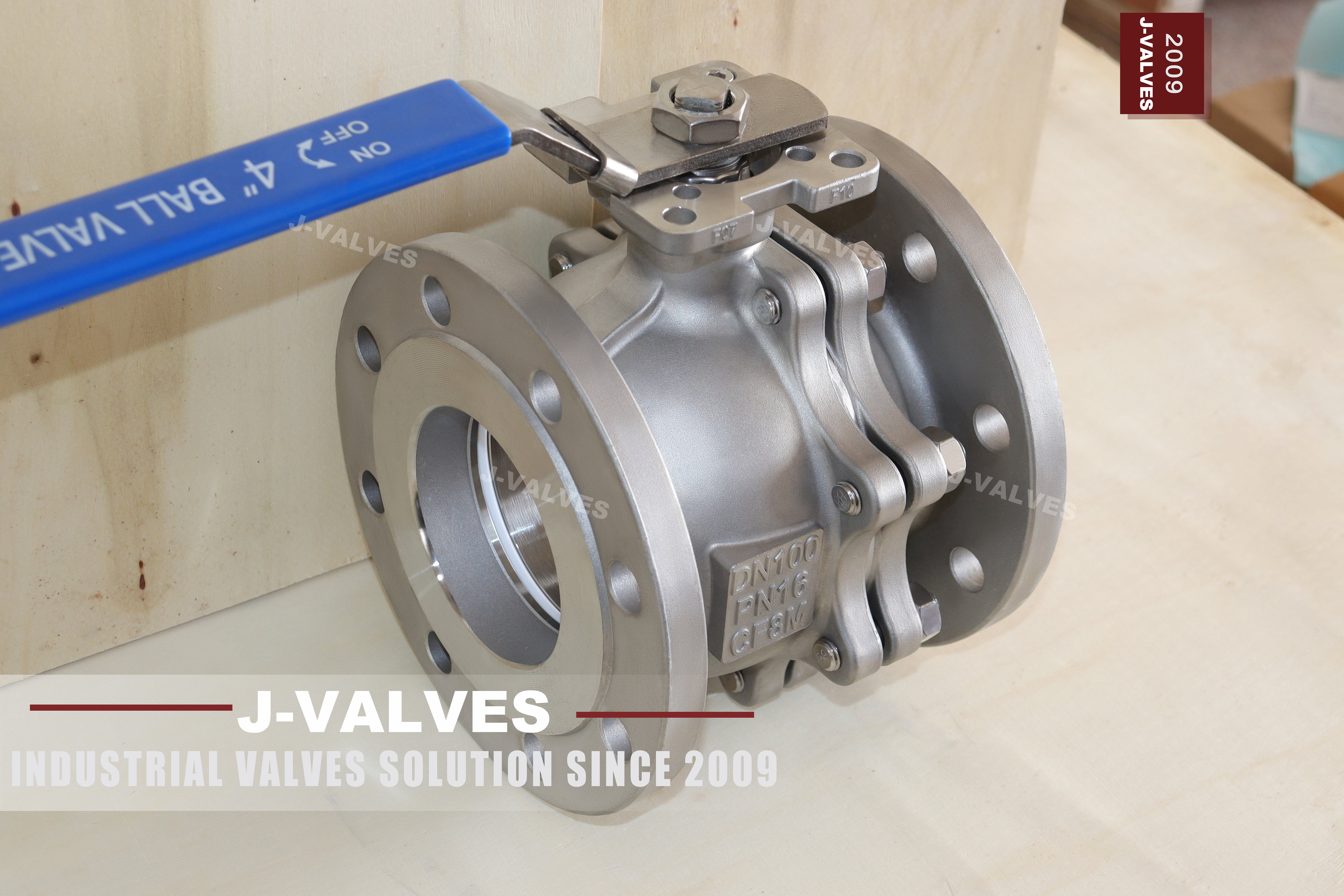
There is a slash in the material column of this valve, and a slash is not a grade. The line reads CF8/CF8M for the body, and the same two designations are copied down the ball row and the stem row, which is how a table written for one part gets applied to three. On a JIS order that slash is the most consequential piece of text on the page, because it is the point where the buyer's choice becomes the supplier's choice.
The valve described is a two piece flanged floating ball valve with flanges drilled to JIS B2220, offered in 10K and 20K, from DN 15 to DN 200, which the Japanese schedule writes as 15A to 200A. It exists for piping classes that are written in the JIS system rather than the ASME one, and it is ordered by size in A and by rating in K rather than by class.
The argument here is narrow and practical. CF8 and CF8M are two different alloys with different chloride resistance, and a quotation that offers both has not offered a valve; it has offered a range. The second half of the argument is that a floating ball is not a casting at all, so the casting designation in the ball row describes the wrong manufacturing route, however true the alloy may be.
Design and Construction
The body is split at one plane and closed by a ring of studs with a gasket, in the same two piece pattern used across this size range. The ball sits on two polymer seat rings and is pushed into the downstream seat by the medium, which means the upstream seat is held by preload rather than by pressure. The stem passes through a shoulder that cannot be blown out and carries an anti static path to the body.
The flange is where this valve stops being interchangeable with an ASME one. JIS B2220 sets its own outside diameter, bolt circle, bolt count and bolt size for each nominal size and each K rating, and those figures do not track ASME B16.5 even where the two flanges look similar from a distance. The bore, the face to face length and the body may all be right while the drilling is wrong.
The seat arrangement is the ordinary floating one and it has one consequence worth stating before the material section. Because the ball can only move downstream, the upstream seat sees pressure from behind rather than from the ball, and the seal there depends on the preload built into the seat and its spring. On a JIS valve with a soft seat, that preload is also what keeps the seat in contact at low pressure, where the medium alone would not be enough.
The body carries a mounting pad on the actuated version, drilled to ISO 5211, and the pad is cast or machined into the body rather than bolted on. That matters because the pad is the interface that a switch box, a gearbox or a pneumatic actuator is selected against, and a pad added by bracket rather than by casting puts the actuator load into four small studs instead of into the body.

Material Options
The material table on the page lists three parts with the same two designations, and the table below separates them, because a body, a ball and a stem are made by three different processes even when they end up as the same alloy.
| Part | Material on This Build | How the Part Is Made |
|---|---|---|
| Body and end piece | CF8 or CF8M, one grade | Cast, then machined |
| Ball | F304 or F316 bar | Turned, ground and lapped |
| Stem | F304 or F316 bar | Turned from bar, shoulder formed |
| Seats | PTFE or reinforced PTFE | Moulded ring, machined face |
| Body joint gasket | Spiral wound or PTFE sheet | One joint, one gasket |
| Studs and nuts | A2 or A4 stainless | Sized by the K rating |
| Anti static | Spring or conducting washer | Stem to body |
| Fire safe insert | Metal lip behind the seat | To API 607 |
CF8 is the cast equivalent of 304 and CF8M is the cast equivalent of 316, and the Japanese designations for the same two castings are SCS13 and SCS14. The difference that matters in service is molybdenum: CF8M carries it and resists chlorides, CF8 does not and will pit. A cooling water line with a few hundred parts per million of chloride is enough to separate them, and the separation shows up at the seat pocket first.
The ball is turned from bar, not cast. A floating ball has to be spherical to a tolerance that a casting cannot hold without a machining allowance deep enough to cut through the chilled skin, and the sealing band has to be free of porosity because the seat seals on a line contact rather than on an area. Writing CF8 in the ball row describes the alloy family correctly and the manufacturing route incorrectly.
A stem is also bar stock, usually in the same grade as the ball, and its critical feature is not the material but the shoulder that bears against the body. That shoulder is what makes the stem blowout proof: it is larger than the bore it passes through, so pressure pushes the stem against the body instead of out of it. No casting designation has anything to say about that feature.
Technical Specifications
The specification below is the page's own, with the two grading lines corrected to the way the parts are actually made.
| Item | Value |
|---|---|
| Size range | DN 15 to DN 200, written 15A to 200A |
| Pressure rating | JIS 10K and JIS 20K |
| Body | CF8 or CF8M, one grade per valve |
| Ball and stem | F304 or F316 bar |
| Seats | PTFE or reinforced PTFE |
| Temperature | Minus 29 to plus 200 Celsius |
| Ends | Flange to JIS B2220, 10K or 20K drilling |
| Face to face | JIS B2002 |
| Design | JIS B2071 general rules, ASME B16.34 for wall and groups |
| Test | JIS B2003 and API 598 |
| Fire safe | API 607 |
| Operation | Lever, gear, or pneumatic on a pad |
The 20K rating is worth a paragraph of its own because it is often treated as a 10K valve with a higher number on the plate. K is a kilogram force per square centimetre designation rather than a bar figure, so 20K is nominally about two megapascals against one for 10K. What changes with it is not only the wall but the flange: the 20K flange is thicker, its bolt circle moves outward and its bolt count can differ, so a 20K valve does not drop into a 10K piping class even at the same nominal size.
The size column hides a second trap for anyone reading a Japanese specification quickly. The A schedule and the DN schedule name the same bore, so 80A and DN 80 are the same valve, but the letter is part of the order. A plate reading 80A is not a different size from one reading DN 80, and a buyer who treats the two as different sizes will end up ordering twice.
Standards and Compliance
Four JIS documents and one ASME document appear in the page's standard lines, and they divide the work in a way that is worth setting out, because a single line listing them suggests they are interchangeable.
| Document | What it fixes | What it does not fix |
|---|---|---|
| JIS B2071 | General rules for valves | Any dimension a fitter needs |
| JIS B2220 | Flange dimensions and drilling by size and K rating | The valve body or its seats |
| JIS B2002 | Face to face dimensions | Flange drilling or test pressure |
| JIS B2003 | Test methods for valves | The allowable leakage of a specific design |
| ASME B16.34 | Wall thickness method and material groups | JIS flange dimensions |
A quotation that says only that the valve is built to JIS B2071 has named a general rules document and stopped there. The three documents that a fitter and an inspector actually work from are B2220 for the flange, B2002 for the length and B2003 for the test, and each of them has to appear on the order if the valve is to arrive usable. The page does list all three, which is more than most competitor pages do.
The ASME document is not out of place next to the JIS ones, because the two systems answer different questions. B16.34 gives the method for the wall and the grouping of the material, and the JIS documents give the geometry and the test. A JIS valve built to a wall derived from an ASME group table is normal practice in export work, and it is worth saying so rather than leaving the buyer to wonder why an ASME number is on a Japanese valve.
Manufacturing Process
Body castings arrive with the flange boss, the port and the mounting pad formed, and the first operation after fettling is the machining of the flange face. That face becomes the reference for everything that follows, because the seat pocket has to be square to it and the bore concentric with it. A body that is turned over between the face and the pocket produces a valve that seals on part of the ring and weeps on the rest, and no amount of seat preload will fix it.
The ball is machined in three stages: turned to a rough sphere, ground, then lapped against a master so that the sealing band is a true circle. The bore through the ball is machined after the sphere, because holding a sphere by its bore is easier than holding a bored sphere by its outside. The result is checked for sphericity and for surface finish on the band, and the band is the only part of the ball that has to be perfect.
Assembly is a sequence rather than a single step. The seats and their springs go into the pockets, the ball is set between them, the gasket is placed and the second body half is closed on its studs to a controlled torque. The stem, the packing and the lever follow, and the valve is cycled by hand before it goes to test, because a ball that is pinched by a distorted seat will show up as a stiff quarter turn before it shows up as a leak.

Quality Control and Testing
The shell test is applied to the assembled body with the ball open, at the pressure JIS B2003 and API 598 both call for, and the body joint is watched as closely as the wall. The seat test follows with the valve closed, one side at a time, because a floating ball only loads the downstream seat and the other seat has to be proven by turning the valve around.
Dimensional checks on a JIS valve concentrate on the flange, and the drilling is where a mistake is expensive. Bolt count, bolt size, bolt circle and the thickness of the flange are checked against B2220 for the size and the K rating, and a valve that passes every pressure test but fails the drilling cannot be installed at all. That check is done on the bench with a template rather than with a caliper.
The grade is confirmed from the certificate rather than from the plate, and this is where the slash on the page becomes a quality issue. A plate reading CF8 and a certificate reading CF8M is a valve that will be rejected at goods-in, and a plate reading CF8/CF8M is a valve that has not answered the question. One grade on the plate, one grade on the certificate, and the same grade in both places is the only acceptable arrangement.

Applications and Industry Service
The reason a buyer asks for a JIS valve rather than an ASME one is almost always the piping class, not a preference for the standard. Shipyards, Japanese owned plants, and projects in Southeast Asia where the specification was written in the JIS system all produce piping classes that call for 10K flanges, and a valve with ASME drilling is of no use on that line however well it is made.
Within that market the CF8 grade covers treated water, chilled water and most building services, while CF8M covers the chemical and coastal work where chloride is present. The 20K version extends the same body pattern into higher pressure services, at the cost of a heavier flange and a different bolt pattern, which is why a plant that standardises on 10K cannot simply upgrade a line without checking the mating flanges.
Steam and hot water above the seat limit are outside this valve for the same reason they are outside every polymer seated floating valve, and the page's own 200 Celsius ceiling is honest about it. Where the duty is hotter, the seat has to change material and the valve becomes a different product with a different torque and a different price, and that change should be made at the enquiry rather than at the failure.

Installation, Operation and Maintenance
Installation is a JIS flange joint at each end, with a gasket to suit the raised face and bolts to B2220 for the size and rating. The bolts are the part that gives trouble when a valve has been bought on price alone, because a flange drilled to 10K will not accept the bolts that a fitter brought for an ASME joint of the same nominal size, and the line stops until the right ones arrive.
Operation is a quarter turn and the valve is an isolator rather than a regulator. Leaving a floating ball at part open puts the flow across the seat edge at high velocity and erodes the polymer in a way that no pressure rating anticipates. On the actuated version, the pad should be checked before the actuator is ordered, because the bolt circle and the drive form are what decide which unit fits.
Maintenance is limited by the two piece body. The packing can be adjusted from the top, the lever and the plate come off with the packing nut, and the seats and ball need the joint opened, which means the valve comes off the line. On a JIS valve in a shipyard the practical answer is usually to carry a spare rather than to rebuild on board, and the two piece pattern makes that a reasonable policy rather than an expensive one.
How to Specify and Order
The order lines below are the ones this page leaves open, and the first two are the ones that decide what actually arrives.
| Line on the order | What to write | Why it matters |
|---|---|---|
| Body grade | CF8 or CF8M, one only | The slash is an option list, the plate carries one grade |
| Ball and stem | F304 or F316 bar | Casting designations describe the wrong process |
| Size and rating | For example 80A 10K | The A schedule and the K rating are both order data |
| Ends | JIS B2220, 10K or 20K drilling | The drilling does not match ASME at the same size |
| Operator | Lever, gear, or pneumatic | The pad is an ISO 5211 interface where fitted |
The grade line is not a formality. A quotation that carries both grades has left the choice to the supplier, and the supplier will choose the one that is cheaper or more available that month. Writing one grade costs nothing and removes the only material decision on the valve from the packing desk.
Written that way, the valve is a known object: a two piece JIS flanged body in one named grade, a bar stock ball and stem, polymer seats with a 200 Celsius ceiling, JIS drilling at a stated K rating, and a face to face length to B2002. The slash survives on the page as an option, and it disappears from the order, which is where it does its damage.
FAQ
Q: Which grade do I get when the offer says CF8/CF8M?
A: Whichever is available that week, unless the order names one. The slash is an option list, not a specification, and on a quotation it transfers the choice to the supplier. Write one grade, CF8 or CF8M, and let the mill certificate confirm it; the two are not interchangeable where chlorides are present.
Q: Is the ball cast as well, since the table says CF8?
A: No. A floating ball is turned and lapped from bar or from a forging, so its correct name is F304 or F316; CF8 and CF8M are casting designations and do not describe a machined ball. A casting grade in the ball row usually means the row was copied from the body row without being changed.
Q: Will a JIS 10K flange bolt to an ANSI Class 150 flange of the same size?
A: No. The two drillings are different, and at DN 80 the JIS 10K flange carries eight bolts where a three inch Class 150 flange carries four. The outside diameters can look close enough to try, which is why the mistake is made on site rather than on the drawing.
Q: What is 20K in bar?
A: About two megapascals nominal, twice the 10K figure, because K is a kilogram force per square centimetre designation rather than a bar figure. The flange does not simply scale with it: the 20K flange is thicker and its bolt circle moves, so a 20K valve will not drop into a 10K piping class.
Q: Why does the plate say 80A when my drawing says DN80?
A: Both name the same bore. The A schedule is what a Japanese specification calls the size; DN is the ISO way of writing it. The number is the same, the letter is not, and a plate that carries 80A is not a different valve from the one on a DN80 line.
Hot Products


News
Remanufactured Ball Valves: Five Checks That Decide Whether A Rebuild Deserves A Certificate
A rebuild at 45 percent of price with half the life is no saving. Five checks that separate a real remanufacture from a repaint with a certificate.
Read More
The Squeeze Is A Residual: How Tolerance Stack-Up Decides Whether A Ball Valve Seals
No dimension sets the seat squeeze. Five tolerances do, in series. Why identical valves feel different, and why a new ball changes the arithmetic.
Read More
Why A Ball Valve Gets Harder To Turn: Five Causes, And The Test That Tells Them Apart
A ball valve that stiffens over months points at one of five parts. Measure torque with the line pressurised and again vented, and the split becomes visible.
Read More
The Ball Valve at Four Thousand Bar: Seat Load, Erosion And Fatigue in Waterjet Circuits
At 4,000 bar a 10 mm bore puts 31 kN on the seat and a 0.1 mm leak cuts steel. What a ball valve must survive in a waterjet or intensifier circuit.
Read More