CHINA J-VALVES Offers Various High-quality I ndustrial Ball Valves
J-VALVES, a distinguished professional ball valve manufacturer rooted in China, takes pride in its extensive product portfolio. Our offerings span a wide range, including trunnion-mounted ball valves, floating ball valves, high-temperature ball valves, high-pressure ball valves, metal-sealed ball valves, ultra-low temperature ball valves, DBB ball valves, Three-way And Four-way Ball Valve, and fully welded ball valves. Each product is a testament to our commitment to precision engineering and reliable performance. Meticulously crafted, they are designed to not only meet but exceed the most stringent industrial demands, ensuring stable operation even under extreme conditions. This enables us to provide our clients with high-value services and makes our valves widely sought-after in industries.
Product Category
Contact Us


-
J-VALVES-Q41F
-
MSNL
Overview of the J-VALVES two piece flanged floating ball valve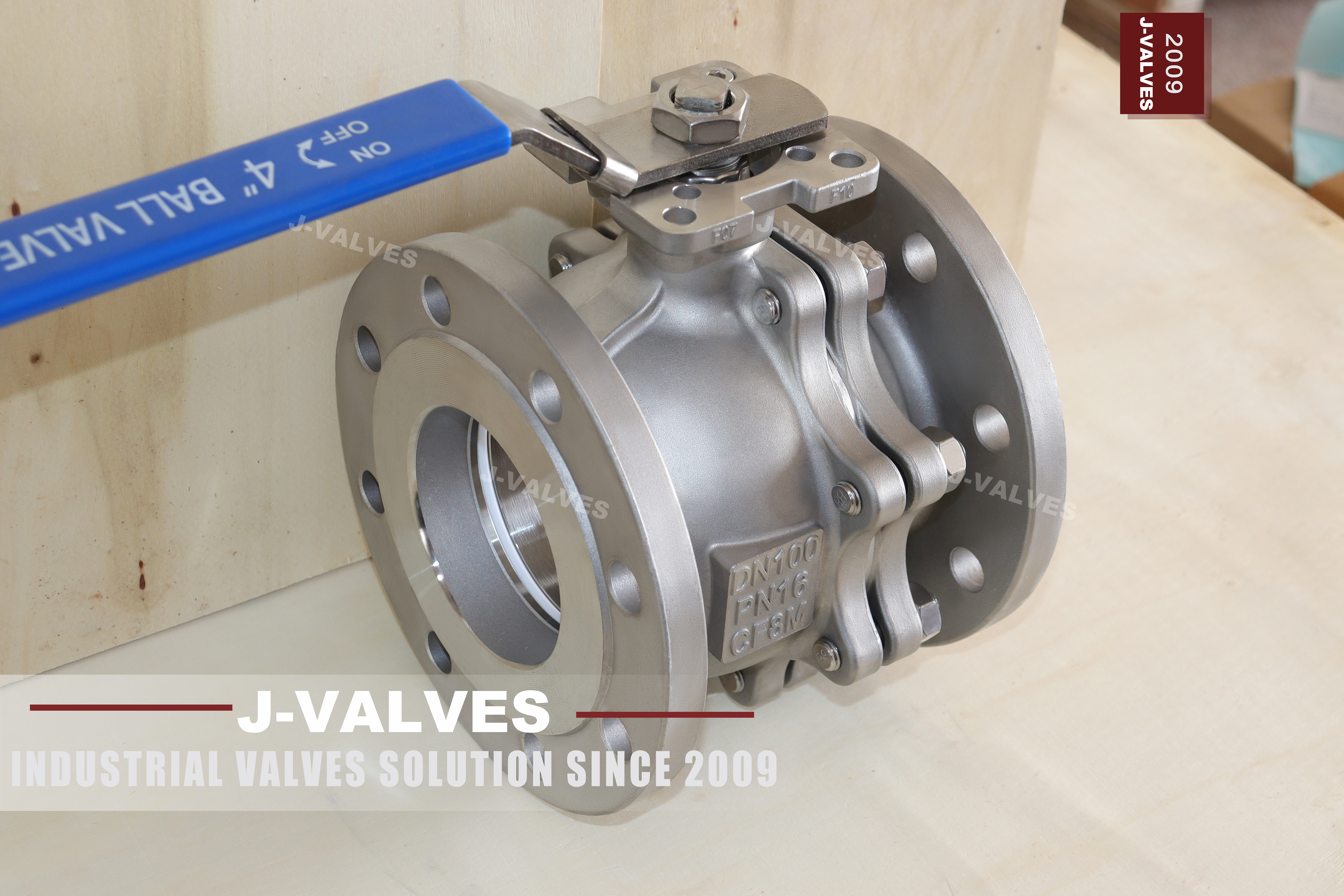
Two numbers close this range, and neither of them is a preference. The first is eight inches, the largest size in which the ball is still held by nothing except its two seats. The second is the temperature at which a polymer seat stops being a seat. Everything else on this page, the 304 or 316 body, the raised face, the lever, the two piece joint, follows from where those two lines fall.
The valve in the photograph is a two piece stainless body with a single bolted joint, raised face flanges to ASME B16.5 and a lever on top, offered from half inch to eight inch in Class 150 to Class 600. It is the pattern that fills most plant water, oil and gas isolation duty, and the reason it is offered up to eight inches rather than twelve is not a limit on the casting.
The argument of this page is that both ends of the range are mechanical. A floating ball is pushed into its downstream seat by line pressure, so the seat load is made by the medium rather than by a spring or a piston, and that load grows faster than the body does. The temperature end of the range is made by the seat material in the same direct way. Neither number can be moved by writing a larger figure on a datasheet.
Design and Construction
The body is split into two halves at one plane, usually just behind the seat pocket on the upstream side, and the two halves are closed by a ring of studs with a gasket between them. That joint is a pressure boundary and it is tested as one. The end that carries the joint also carries the seat pocket and the flange, so a single setting can produce the pocket, the bore and the flange face concentric with each other.
Inside, the ball rests on two seat rings and on nothing else. There is no trunnion, no bearing and no stem support taking the thrust. When the line is pressurised, the medium enters the body and pushes the ball downstream until it presses into the downstream seat. That seat is therefore loaded by the medium itself, and the sealing force rises with the pressure and with the area of the bore.
The upstream seat works the other way. It is held against the ball by its own preload, which comes from the seat geometry and from the small spring or wave washer behind it, and the medium does not add to that load because the ball has moved away from it. This asymmetry is the single most useful thing to understand about a floating valve, because it explains why a seat test is run twice and why one leaking seat does not always mean a failed valve.
The two piece joint is often described as making maintenance easier, and that is a consequence rather than a reason. What the joint buys is one gasketed boundary instead of the two that a three piece body needs, and what it costs is that the ball and both seats can only be reached from one side. A three piece body opens from either end; a two piece body has to be pulled from the line and split in one direction.
The stem passes through the body on a shoulder that is larger than the packing bore, so pressure cannot eject it, and a spring or a set of conducting washers bridges the stem to the body to drain static charge. The fire safe design puts a lip or a secondary seat behind the polymer so that the seat ring, when it burns away, leaves a metal to metal path that still restricts flow in the direction the fire is coming from.

Material Options
The page offers two body grades and one ball grade, and the difference between the two body grades is the only material decision that a buyer usually makes on this valve. The table below keeps the page's own entries and adds only what the seat and the joint need in order to be ordered.
| Part | Material on This Build | Note |
|---|---|---|
| Body and end piece | 304 or 316 stainless | One grade for the whole body |
| Ball | 316 stainless, polished | Floating, no trunnion |
| Stem | 316 stainless | Blowout proof shoulder |
| Seats | PTFE or reinforced PTFE | Sets the temperature ceiling |
| Body joint gasket | Spiral wound or PTFE sheet | One joint, one gasket |
| Studs and nuts | A2 or A4 stainless | Sized by the class |
| Anti static | Spring or conducting washer | Stem to body |
| Fire safe insert | Metal lip behind the seat | To API 607 |
The 304 and 316 choice is about chlorides rather than about strength. Both are austenitic and both are more than strong enough for the wall that B16.34 requires at these classes. What separates them is resistance to pitting in water that carries chloride, and a 304 body in a brackish cooling line will pit at the seat pocket long before anything mechanical fails.
The seat is where the temperature is decided. PTFE and reinforced PTFE both run to about 200 Celsius in continuous service, and the reinforced grade holds its shape better at the top of that band because the filler reduces cold flow. Above that band the polymer softens, the seat extrudes into the clearance and the valve stops sealing rather than failing visibly, which is the worse of the two outcomes.
The page prints a range up to 425 Celsius, and no polymer seat reaches that figure. The 425 belongs to the stainless body, and it is the kind of number that comes from a material table rather than from a valve test. A buyer who orders this valve for a 300 Celsius line will receive a valve whose body is comfortable and whose seats are outside their range, and the failure will be put down to the medium.
Technical Specifications
The specification below is the page's own range with the seat limits applied, and it is the version that should be quoted.
| Item | Value |
|---|---|
| Size range | Half inch to eight inch, DN 15 to DN 200 |
| Pressure class | Class 150 to Class 600, PN 20 to PN 100 |
| Body | 304 or 316 stainless, two piece, one joint |
| Ball | 316 stainless, floating |
| Seats | PTFE or reinforced PTFE |
| Temperature | Minus 29 to plus 200 Celsius on a polymer seat |
| Ends | Raised face to ASME B16.5 |
| Face to face | ASME B16.10 |
| Design | ASME B16.34, API 608 |
| Test | API 598 shell and seat |
| Fire safe | API 607 |
| Operation | Lever, gear, or pneumatic on an ISO 5211 pad |
The class to PN pairing on this page is correct and worth keeping, because the same pairing is often printed wrongly. Class 150 is PN 20, Class 300 is PN 50 and Class 600 is PN 100, and those three come from the designation table in API 6D rather than from a conversion in bar. A page that prints PN 16 against Class 150 has converted a pressure instead of reading a table.
Eight inches is the end of the range because the seat load is made by the ball. The force that pushes the ball into the seat is the line pressure multiplied by the area it acts on, so it rises with the square of the bore while the seat ring and the stem only grow with the diameter. At some size the friction that the seat load creates needs more torque than a lever can give and more stiffness than a floating ball can hold, and the answer is a trunnion valve, where the ball is carried on bearings and the seat is pushed by a piston.
Standards and Compliance
Three documents are cited on the page and two more are needed to describe what is actually being bought. The table sets out what each one fixes and, more usefully, what it leaves to somebody else.
| Document | What it fixes | What it does not fix |
|---|---|---|
| ASME B16.34 | Wall thickness and material groups, hence the pressure and temperature ratings | The valve's own design details |
| API 608 | Steel ball valve requirements, DN 15 to DN 600, Class 150 to Class 600 | Anything above Class 600 |
| ASME B16.5 | Flange dimensions and drilling | The valve body or its seats |
| ASME B16.10 | Face to face for flanged valves | Threaded or welded lengths |
| API 598 | Shell and seat test procedure and allowable leakage | The seat material choice |
The division between B16.34 and API 608 is the part that buyers most often collapse into one line. B16.34 is a pressure boundary document: it tells you how thick the wall must be for a material group at a class and a temperature, and it is the reason a 316 body and a 304 body can share a casting pattern at the same class. API 608 is a product document: it describes what a steel ball valve has to do, how it is marked, and how it is tested.
API 607 is the fire test and it is a type test rather than a routine one, which matters when a certificate is being read. It says that a valve of this design, in a size and class, was tested once and passed. It does not say that the valve in the crate was tested, and it does not replace the shell and seat test that every unit receives to API 598.
Manufacturing Process
The body halves begin as castings or, at the smaller sizes and higher classes, as forgings. Castings bring the port, the flange boss and the mounting pad in one piece and need radiography or penetrant checks at the sections that carry pressure. Forgings bring density and a grain flow that follows the shape, and they are chosen where the wall is thin and the class is high rather than because they are inherently stronger.
Machining is where the geometry of a floating valve is actually made. The seat pocket, the bore and the flange face are cut in one setting with the flange face as the reference, because the pocket has to be square to the face and concentric with the bore. If the body is turned over between the pocket and the face, the seat sits at a small angle and the ball seals on one side of the ring.
After machining, the two halves are cleaned, the seat rings and the gasket are fitted, and the body is closed on its studs to a controlled torque. That torque is part of the design: too little and the gasket weeps at the joint, too much and the body half distorts the seat pocket. The ball is fitted before the joint closes, and its freedom to move a fraction of a millimetre is what the whole design depends on.

Quality Control and Testing
Every unit gets a shell test at one and a half times the class rating and a seat test at one point one times, both to API 598, and both with the valve in the open position for the shell and closed for the seat. The shell test is applied to the body with the ball open so that both body halves and the joint see the pressure; the seat test is applied to one side at a time.
The seat test is run twice because only one seat is loaded by the medium. With pressure on the upstream side, the ball is pushed into the downstream seat and that seat is proven. Turn the valve around and the other seat is proven. A test that pressurises one side and calls the result a seat test has proved one seat and assumed the other, which is the assumption that fails in service.
Fire safe and anti static behaviour are type tested rather than unit tested, but the anti static path can be checked on every valve with a resistance meter between stem and body, and that check is cheap enough that there is no reason to skip it. The plate carries size, class, body grade and heat number, and the heat number is the line that ties the valve to the certificate and to the cast or forged batch behind it.

Applications and Industry Service
The duty this pattern covers is isolation, not control. Water, oil and gas at ambient to moderately warm temperatures, in lines from half inch to eight inch, at classes up to 600, is where a floating ball valve is the cheapest thing that does the job properly. Chemical transfer in 316, cooling water in 304, and fuel and lube lines in either grade are the three families that account for most of the volume.
In buildings the same valve appears on heating and chilled water headers, and there the 304 grade is usually enough because the water is treated and the chloride load is low. In food and beverage plants the argument for the pattern is the straight through bore and the absence of a pocket, provided the seat and gasket materials are chosen for the cleaning regime rather than for the pressure.
Where the pattern should not be used is as clear as where it should. Steam above the seat limit, media that flash across the seat, and lines that need throttling are all outside what a polymer seated floating ball can do. A ball valve is a quarter turn isolator; half open it puts a jet across the seat edge and destroys it, and no amount of derating makes it a control valve.

Installation, Operation and Maintenance
Installation is a flange joint at each end, with a gasket to match the raised face and studs sized for the class. The valve can go in either direction because the body is symmetric in pressure terms, though the preferred direction is usually marked and follows the seat arrangement. The joint studs are tightened in a cross pattern, and the pipe is supported so that the valve body is not carrying the weight of the line.
Operation is a quarter turn, and the lever should end against a stop rather than being forced. The valve is not a throttling device and the lever is not a handle for partial opening; a ball left at forty five degrees will erode its seat at the edge where the jet passes. Locking the lever in the open or closed position is normal practice on a line that must not be moved by accident.
Maintenance is limited to the parts that can be reached. The stem packing can be adjusted or replaced from the top without breaking the body joint, and the lever and the plate come off with the packing nut. The seats and the ball need the joint opened, which means the valve comes out of the line, and on a two piece body that is the only way in.
How to Specify and Order
An order for this valve needs two lines that the page leaves open, and the table sets them out. Everything else can be read from the model and the class.
| Line on the order | What to write | Why it matters |
|---|---|---|
| Body grade | 304 or 316, one of them | The page offers a choice and the plate carries one grade |
| Seat material | PTFE or reinforced PTFE | Sets the temperature ceiling |
| Size and class | For example four inch Class 300 | Fixes the flange, the face to face and the wall |
| Ends | Raised face, ASME B16.5 | Ring joint and butt weld are different builds |
| Operator | Lever, gear, or actuator with pad | The pad is an ISO 5211 interface, not a bracket |
The grade line is the one to write explicitly, because a quotation that copies the page will carry both grades and leave the choice to whoever packs the order. The seat line is the one that decides whether the valve can be used at the temperature the line actually runs at, and it is the only line on the order that changes the answer to the eight inch question.
Ordered this way, the valve is a known object: a two piece stainless body, one joint, a floating ball on two seats, raised face flanges, and a temperature ceiling that belongs to the seat rather than to a figure borrowed from a material table. That is a narrower description than the page gives, and it is the one that will still be true when the valve is on the line.
FAQ
Q: Why does a floating valve stop at eight inches?
A: Because the seat load is made by the ball, and the ball is pushed by the medium. That push rises with the area of the bore, so a seat force rises roughly with the square of the size while the metal around it does not. Above eight inch the same duty is given to a trunnion valve, where the ball is held by bearings and the seat is pushed by a piston instead of by the ball.
Q: The page prints 425 Celsius. Can this valve run there?
A: Not on a polymer seat. PTFE and reinforced PTFE top out near 200 Celsius in continuous service, and that is the figure this article uses. The 425 belongs to the stainless body, which is not the part that fails first. If the duty is above 200, the seat has to become polyimide or metal, and that is a different valve with a different torque.
Q: Does the two piece joint make the body weaker?
A: No. The joint is a pressure boundary, not a reinforcement. It carries a gasket and a ring of studs and it is tested like any other boundary. What it costs is one more place to leak and a body that has to be split before the ball comes out; what it buys is a single joint instead of the two a three piece body needs.
Q: Is ASME B16.34 or API 608 the design standard?
A: Both, and they do different jobs. B16.34 sets the wall thickness and the material group, which is where the pressure and temperature ratings come from. API 608 sets the requirements of the valve itself from DN 15 to DN 600 in Class 150 to Class 600. A valve needs both documents and neither one replaces the other.
Q: Why is one seat said to be pressure energised and the other not?
A: Because the ball can only move one way. Line pressure pushes the ball downstream into the downstream seat, so that seat is loaded by the medium. The upstream seat is held against the ball by its own preload and the spring behind it. This is why a seat test on a floating valve is run one side at a time.
Hot Products


News
Remanufactured Ball Valves: Five Checks That Decide Whether A Rebuild Deserves A Certificate
A rebuild at 45 percent of price with half the life is no saving. Five checks that separate a real remanufacture from a repaint with a certificate.
Read More
The Squeeze Is A Residual: How Tolerance Stack-Up Decides Whether A Ball Valve Seals
No dimension sets the seat squeeze. Five tolerances do, in series. Why identical valves feel different, and why a new ball changes the arithmetic.
Read More
Why A Ball Valve Gets Harder To Turn: Five Causes, And The Test That Tells Them Apart
A ball valve that stiffens over months points at one of five parts. Measure torque with the line pressurised and again vented, and the split becomes visible.
Read More
The Ball Valve at Four Thousand Bar: Seat Load, Erosion And Fatigue in Waterjet Circuits
At 4,000 bar a 10 mm bore puts 31 kN on the seat and a 0.1 mm leak cuts steel. What a ball valve must survive in a waterjet or intensifier circuit.
Read More