CHINA J-VALVES Offers Various High-quality I ndustrial Ball Valves
J-VALVES, a distinguished professional ball valve manufacturer rooted in China, takes pride in its extensive product portfolio. Our offerings span a wide range, including trunnion-mounted ball valves, floating ball valves, high-temperature ball valves, high-pressure ball valves, metal-sealed ball valves, ultra-low temperature ball valves, DBB ball valves, Three-way And Four-way Ball Valve, and fully welded ball valves. Each product is a testament to our commitment to precision engineering and reliable performance. Meticulously crafted, they are designed to not only meet but exceed the most stringent industrial demands, ensuring stable operation even under extreme conditions. This enables us to provide our clients with high-value services and makes our valves widely sought-after in industries.
Product Category
Contact Us


-
J-VALVES-Q41F
-
J-VALVES
Overview of the J-VALVES DBB flanged by threaded ball valve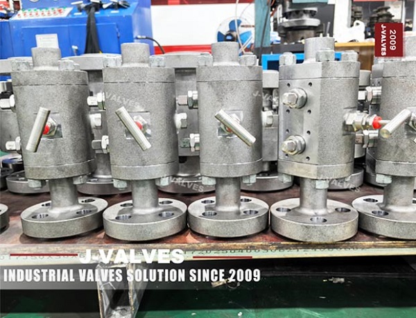
Most valves have the same connection at both ends, and the reason is that a valve is normally a piece of pipe with a mechanism inside it. This one is different: one end is a flange, the other end is a male thread. That makes it an adapter as well as a valve, and the adapter role is what decides how it is specified, how it is installed and where the load goes.
The body photographed here reads one half by one half, Class 600, A105N, with a four bolt flange at one end, a threaded end at the other, two levers on top and a bleed plug underneath. It is a floating ball design, duplicated: two balls, two stems, one body, and a bleed port into the space between them.
The argument of this page is about the joint that is not a joint. A flanged end is bolted to a flange and the bolting takes the load. A threaded end screws into a fitting and the thread takes the load, in a form that has no flange face to react a bending moment. A valve with one of each is a valve that will be asked to carry a load its threaded end was never designed to resist, and the installation rules are the only thing standing between that valve and a leak at the thread.
Design and Construction
The body is a forged carbon steel barrel with a ball and seat stack at each end, closed by end pieces. Two stems come out of the top, each with its own lever, and each drives one ball. The bleed is a plug at the bottom of the centre section, reached with a wrench rather than with a hand, which is a deliberate choice on a valve this size: a needle valve on a half inch body would be larger than the body.
The floating ball arrangement is what makes the second ball necessary. A single floating ball is pushed downstream by the pressure and seals on the downstream seat; the upstream seat is not loaded and does not seal, so a single floating ball is one barrier and not two. Adding a second ball gives the valve two independent elements, and that is what a double block and bleed function actually requires.
The two balls sit in one body with a cavity between them, and the bleed plug reaches that cavity. Each ball has its own seat pair, and on a floating design both seats in a pair are the same part, because the ball moves to whichever seat the pressure pushes it against. That is a simpler stack than a trunnion valve and it is why the body can be as small as it is.
The flange end is a standard raised face flange with four bolt holes at this size and class, and it bolts to a pipe flange in the normal way. The threaded end is a taper thread cut on the outside of the end piece, and it seals by interference between the thread flanks of the male and female parts, with a sealant or a tape filling the spiral leak path that a taper thread leaves.

Material Options
The body and the end pieces are A105N forged carbon steel, stamped on the body and on the ends, and the trim follows the same small bore logic: stainless ball and stem, polymer seat, and a carbon steel body that is small enough to be forged from bar.
| Part | Material on This Build | Note |
|---|---|---|
| Body and end pieces | A105N forged carbon steel | Normalised, recorded per heat |
| Balls | Stainless, hardened | Two, one per stem |
| Stems | Stainless | One per ball, independent levers |
| Seats | Reinforced PTFE or polyimide | Sets the temperature limit |
| Body joints | O ring or gasket at each end piece | Two joints on a two ball body |
| Bleed plug | Stainless or carbon steel with a seal | Reached with a wrench |
| Flange end | Raised face to ASME B16.5 | Four bolt holes at this size |
| Thread end | Taper thread to ASME B1.20.1 | Seals on the thread flanks |
The A105N grade is worth one line because it is the most commonly abbreviated one on a small bore order. The N records that the forging was normalised after forging, which is a heat treatment and not a grade. An order that says A105N and asks for no heat treatment record has asked for a condition and left the evidence of it to the supplier.
The thread is the material decision that is not a material decision. A taper thread cut into a forged end piece is a stress concentration at the last engaged thread, and on a small valve that thread is the thinnest part of the pressure boundary. Nothing in the flange standard covers it, which is why the rating of the assembly is not the rating of the flange.
Technical Specifications
| Item | Value |
|---|---|
| Size range | One half inch to two inch, DN 15 to DN 50 |
| Build shown | One half by one half inch, Class 600 |
| Pressure class | Class 150 to Class 2500, PN 20 to PN 420 |
| Body | Forged A105N, two balls, two stems |
| Ends | One raised face flange, one taper thread |
| Bore | Full or reduced, by the model |
| Sealed volumes | Two seat cavities and one between the balls |
| Bleed | Plug into the middle volume |
| Temperature | Minus 46 to plus 200 Celsius, seat dependent |
| Operator | One lever per stem |
| Design | API 6D, ASME B16.34, API 608 |
| Test | API 598 shell and seat, plus a cavity proof |
Class 600 is PN 100 in the API 6D designation list, and the pairing is correct on this build. The list is short and it is worth memorising in full because the errors on small bore pages concentrate here: 150 is PN 20, 300 is PN 50, 600 is PN 100, 900 is PN 150, 1500 is PN 250 and 2500 is PN 420.
The rating line that matters on this valve is not in the table above, because the table describes the flange end. A flanged by threaded valve is rated by the weaker of its two ends, and the threaded end has no flange standard behind it. The thread rating comes from the wall thickness of the end piece, the thread form and the engagement length, and the only place that combination is stated is the drawing.
Standards and Compliance
| Requirement | Document | What It Means Here |
|---|---|---|
| Product requirements | API 6D | Design, materials, marking, DBB function |
| Alternative product standard | API 608 | Only to DN 600 and Class 600 |
| Wall and rating | ASME B16.34 | Sets the wall for the class and group |
| Flange end | ASME B16.5 | Facing, bolt circle, facing height |
| Thread end | ASME B1.20.1 | The taper thread form and gauging |
| Pressure test | API 598 | Shell at 1.5 times, seat at 1.1 times |
| Material certificate | EN 10204 3.1 | Heat number per pressure part |
ASME B1.20.1 defines the thread form, and it does not define a pressure rating. That is the sentence that decides a lot of arguments about small valves, because it means a threaded end cannot be quoted as Class 600 in the way a flange can. The class describes the body and the flange; the thread is qualified by the wall and by the test.
The two documents also differ in what they require to be marked and recorded. API 6D asks for a nameplate that names the standard as well as the size, class and material, and it asks for a set of test records that go with it. API 608 asks for its own marking and its own records, and a valve marked to one document and tested to the other is a valve that cannot be received against either without an argument. On a small valve the argument is always more expensive than the valve.
API 608 covers this size and class, and it is the document that most small bore floating valves are actually built to. API 6D also covers it, and the difference between the two documents is a subject of its own, but the practical point here is that a small bore valve quoted to 6D and one quoted to 608 are not the same article, and the purchase order should say which.
Manufacturing Process
The body starts as a forged bar, is machined, and the two bores are cut from the two ends. On a body this small the two seat pockets are cut in one operation with the body held in a collet, which is how a half inch body gets two pockets that are truly coaxial.
The threaded end is cut last, after the flange end and the bores, so that the thread is concentric with the bore. A thread cut before the bore is finished is a thread whose axis is wherever the blank was, and the symptom is a valve that screws in at an angle and loads the first thread on one side.
The flange is drilled on a bolt circle from the same centreline, and the number of holes at this size and class is four. Four holes means the flange can only be oriented in four positions, which is a practical point when the bleed plug has to end up underneath and the flange has to line up with a fixed pipe flange.

Quality Control and Testing
| Step | Check | Acceptance |
|---|---|---|
| 1 Incoming | Heat number against the mill certificate | Chemistry and mechanicals |
| 2 Normalising | Heat treatment record for A105N | Recorded by heat |
| 3 Machining | Two seat pockets from one setting | Coaxial to drawing |
| 4 Thread | Form, gauging and concentricity to the bore | ASME B1.20.1 |
| 5 Shell test | Body and both end joints at 1.5 times | API 598, no leakage |
| 6 Seat test | Four seat faces at 1.1 times | API 598 rate |
| 7 Cavity proof | Pressure one side, bleed watched, then reversed | Dry at the stated hold |
| 8 Final | Thread protected, flange faced, crated | Works standard |
The thread check is the row that has no equivalent on an all flanged valve. A thread is either to gauge or it is not, and a thread that is to gauge but not concentric with the bore is a valve that will screw in and then leak at the seat because the pipe is pulling it sideways. Both checks are needed and only one of them is in the thread standard.
The cavity proof runs the same way as on any two ball valve: both closed, bleed open, pressure on one side, watch the port, then reverse. On a valve this size the cavity is small, so the volume that has to be watched is small, and the trace that indicates a weeping seat appears quickly rather than being diluted in a large body.

Applications and Industry Service
A flanged by threaded valve belongs at the point where a flanged system meets a threaded one: an instrument connection taken off a flanged header, a small bore utility line leaving a flanged manifold, a sample point on a vessel, and the transition between a plant piping class and a piece of vendor equipment with threaded ports.
In all of those the valve is doing two jobs. It is the block valve for the branch, and it is the adapter that lets the branch leave a flanged line without a separate reducing spool and a second joint. That is a real saving in a rack, where every joint is a leak path and every extra fitting is another item to procure.
It is the wrong valve where the branch will vibrate, because the threaded end has no flange to react a bending moment and vibration concentrates at the last engaged thread. It is also the wrong valve where the branch has to be dismantled often, because a taper thread that has been made up and broken several times loses its interference and starts to rely on the sealant.

Installation, Operation and Maintenance
The threaded joint is made up with a sealant or tape on the male thread, hand tight and then a part turn with a wrench on the body, holding the pipe with a second wrench. Turning the valve by its lever to tighten the thread loads the stem and the ball against the seats, and a ball damaged that way leaks in service in a way that looks like a seat failure and is not.
The flanged end goes on last, after the threaded end is made up, because making up a thread rotates the valve and a valve already bolted at one end cannot rotate. That sequence is the whole installation procedure for this valve and it is the step that gets done in the wrong order when the pipe is being pulled into line.
Operation is a quarter turn on each lever, and both are closed for the isolation to be a double block. Closing one lever and opening the bleed gives a single block with a drain, which is a different arrangement and is not what the valve was bought for.
How to Specify and Order
The six entries are size, class, body grade, seat, end connection and operator, and on this valve the end connection entry has to be written twice, once for each end, with the thread standard named. A line that says flanged by threaded has described the shape and left the two standards open, and the flange standard and the thread standard are different documents with different limits.
The second thing to write is which end is which. The two ends are not interchangeable in service, and a valve supplied with the flange on the wrong end cannot be adapted in the field without an extra fitting. A drawing with the flow arrow and the two ends labelled is the cheapest way to prevent that.
Documents to name: the EN 10204 3.1 certificate with the heat number, the normalising record for A105N, the thread gauging report, the shell and seat test record with four seat results, the cavity proof record, and the general arrangement drawing showing which end is flanged, which is threaded, and the engagement length the thread is cut to.
FAQ
Q: Can a floating ball valve be double block and bleed?
A: Not with one ball. A floating ball is pushed downstream by the pressure and seals on the downstream seat, so it is one barrier and not two. This valve is double block because it has two balls on two stems, and the second ball is what makes the second barrier independent.
Q: Which end sets the pressure rating?
A: The weaker one, and on this valve that is the threaded end. A flange has ASME B16.5 behind it; a taper thread has a thread standard that defines the form and not a rating. The thread end is qualified by the wall, the thread form and the engagement length, and that combination is on the drawing.
Q: Why can the threaded end not take a bending load?
A: Because there is no flange face to react a moment. A thread carries load on its flanks and a bending moment puts the load on one side of the engagement, at the last engaged thread, which is the thinnest part of the pressure boundary. A vibrating branch will crack there before it leaks anywhere else.
Q: Which end should be installed first?
A: The threaded end, because making up a thread rotates the valve. A valve already bolted at the flange end cannot be rotated to tighten a thread, so the flange end goes on last and the pipe is aligned to it rather than the other way round.
Q: Is a taper thread a pressure class?
A: No. ASME B1.20.1 defines the thread form and the gauging, and it does not define a pressure rating. The class on this valve describes the body and the flange, and the thread is proven by the wall and by the shell test rather than by a class figure.



Hot Products


News
Remanufactured Ball Valves: Five Checks That Decide Whether A Rebuild Deserves A Certificate
A rebuild at 45 percent of price with half the life is no saving. Five checks that separate a real remanufacture from a repaint with a certificate.
Read More
The Squeeze Is A Residual: How Tolerance Stack-Up Decides Whether A Ball Valve Seals
No dimension sets the seat squeeze. Five tolerances do, in series. Why identical valves feel different, and why a new ball changes the arithmetic.
Read More
Why A Ball Valve Gets Harder To Turn: Five Causes, And The Test That Tells Them Apart
A ball valve that stiffens over months points at one of five parts. Measure torque with the line pressurised and again vented, and the split becomes visible.
Read More
The Ball Valve at Four Thousand Bar: Seat Load, Erosion And Fatigue in Waterjet Circuits
At 4,000 bar a 10 mm bore puts 31 kN on the seat and a 0.1 mm leak cuts steel. What a ball valve must survive in a waterjet or intensifier circuit.
Read More