

1. What the welded body removes — and what it does not
A fully welded ball valve replaces the bolted body joint of a split-body or three-piece design with a girth weld. Body construction generally falls into two forms:
Two-piece welded: the centre body and both end bodies joined by two girth welds;
Three-piece welded: a centre body plus two end caps, three girth welds in total.
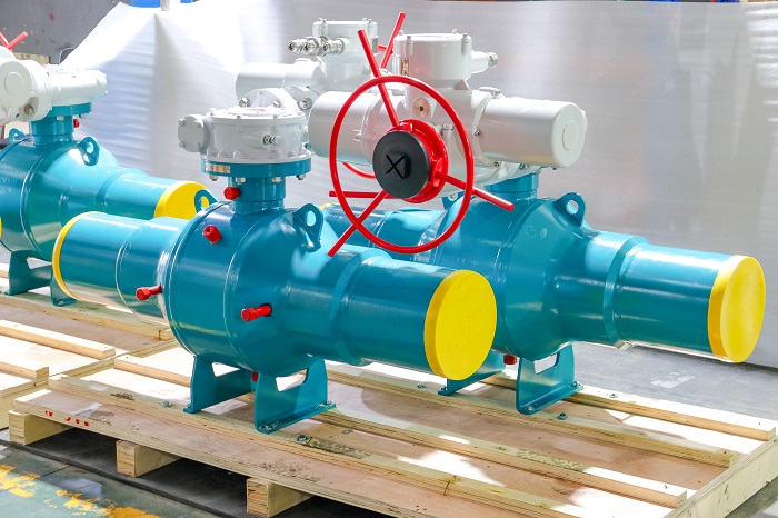
What they share is the absence of a body joint and a body flange. In the unit shown here, the bore ends are protected by yellow caps, the body carries lifting lugs and base support feet, and the actuator is an electric unit — motor, gearbox, and a red manual handwheel for emergency operation.
What the weld removes is the static sealing path: the body gasket and the body bolts. On split-body valves those are the most common source of external leakage and the easiest to overlook. After welding, two external sealing paths remain:
The stem seal — the only maintainable seal on the valve;
The welds themselves — body girth weld and pipe-end butt welds.
What welding does not remove is the service life of the sealing elements. "Fully welded means maintenance-free" is therefore an oversimplification. The accurate statement is that it reduces several maintainable sealing points to one, at the cost of a much harder repair if that one fails.
That is not a criticism — it is the precondition for everything that follows. It is also why half of this article deals with failure modes and boundaries rather than a parameter table.
2. Designing from failure modes backward
Walking the standard textbook order — construction, materials, standards, selection — tends to skip what actually decides the outcome. Failure modes get there faster.
Failure 1: the seat fails, and the seat cannot be changed
Seats and balls in a welded-body valve cannot be replaced in line. Cycle-life rating, seat material endurance, and media cleanliness assessed at the purchase stage effectively commit the next two decades.
Cycle-life testing to API 6D is not a formality here; it is the only evidence of service life you will get. Ask for sealing performance data at a stated cycle count, not a qualitative claim that the valve "lasts a long time."
Failure 2: trapped cavity over-pressure
In the fully closed or fully open position, a ball valve traps a volume of media in the cavity. In liquid service, solar heating or process warming expands that volume, and the pressure can exceed line pressure enough to damage the seat or shift the ball.
API 6D (25th edition) addresses cavity pressure relief explicitly. Confirm two things during selection: where the relief path is, and whether relief is internal (upstream) or external (to atmosphere or a vent system). On natural gas and liquefied hydrocarbon lines this item is not optional.
Failure 3: slow stem-seal leakage
This is the one seal you can maintain, and the real target of low-emission requirements such as ISO 15848-1.
Specify live-loaded packing so the packing load survives thermal cycling, rather than relying on the initial bolt preload to hold it. Packing material matched to the media and temperature determines how many years this point holds.
Failure 4: the actuator does not move when it must
This failure mode is specific to electric actuation, and in the field it is both the most common and the most consequential. It has three independent causes: insufficient torque margin, no ability to act after power loss, and rising static friction from long dormancy. Sections 3 and 4 take them in turn.
3. Torque sizing: why a 1.25 factor fails on a buried line
This is the section worth the most money.
3.1 A ball valve has three torques, not one
Breakaway torque — the moment needed to unseat the ball from the seat;
Running torque — mid-travel, roughly 40–60% of breakaway;
Seating (end) torque — the moment that presses the seal closed at the end of travel.
For ball valves, breakaway usually governs. The ball sits pressed into the seat by differential pressure, and the seat material cold-flows against the ball surface under long contact. The longer the valve sits, the higher the moment required to break it free.
3.2 The pattern that keeps repeating in the field
The buyer takes the datasheet's maximum operating torque, multiplies by 1.25, and orders. Commissioning is flawless. Six months later, a buried or dormant valve is stroked for the first time and the measured breakaway torque runs 20–30% above the datasheet. The actuator trips its torque switch and the valve will not move.
That is not an actuator defect; it is the result of sizing on nominal conditions instead of worst-case conditions. Datasheet torque is published at a stated differential pressure and temperature, while the pipeline may sit at a higher differential pressure for months, with aged grease and a scaled seating surface.
3.3 Safety factors by service
Consistent with common actuator sizing practice and the selection guidance in ISO 22153:2020:
Service | Suggested safety factor |
Clean media, on/off, moderate cycling | 1.25 – 1.5 |
Dirty, scaling, or coking media | 1.5 – 2.0 |
ESD duty, or must stroke after long dormancy | 1.5 – 2.0 |
High temperature (>200 °C), metal seats | 1.5 – 2.5 |
The governing principle is to size for the worst day, not the average. A valve that runs clean 300 days a year and fouls for the other 60 still takes its safety factor from those 60.
3.4 Three checks that must happen together
Torque alone is not enough. These three go together.
MAST (maximum allowable stem torque). The actuator's stall torque must not exceed the stem MAST. Get this wrong and the actuator has plenty of torque — and twists the stem. This is a damage mode that passes commissioning and only shows up later. ISO 22153:2020 requires the valve torque demand (including safety factor) to be checked against the allowable stem torque.
Torque repeatability. ISO 22153:2020 type testing requires torque repeatability within ±10%. Poor repeatability means the same actuator delivers inconsistent output across a stroke, and the torque switch setting stops meaning anything.
Stroke time. On liquid or gas transmission lines, actuator stroke time interacts with pressure wave speed, and can trigger surge or water hammer. Emergency shutdown valves on transmission lines demand transient analysis, not just a torque check. This step is routinely skipped on large-bore, high-velocity lines, and the cost is a surge pressure above design.
4. The point most often missed: an electric actuator is not fail-safe
This is the fundamental difference between electric and pneumatic actuation, and the usual root cause of the wrong actuator type on ESD duty.
A spring-return pneumatic actuator drives the valve to its safe position when air is lost. An electric actuator typically stays where it is (fail-as-is) when power is lost.
A power failure therefore leaves an electric valve wherever it happened to be — possibly full open, possibly mid-travel. If the process requires "close on power loss," a standard electric actuator cannot deliver it. You need one of:
Stored energy — UPS, backup battery, or supercapacitor bank;
An electric actuator with an integrated fail-safe module;
A pneumatic spring-return package instead.
4.1 Write the failure action definition line by line
The specification should state the required action and action time for each of the following separately:
Loss of power (mains interruption);
Loss of signal (broken 4–20 mA loop, communications failure);
Loss of supply air (where a pneumatic backup exists);
Logic when the manual override is engaged.
Leave these undefined and commissioning becomes a commercial dispute: the supplier implements "stay put," the user assumed "must close."
4.2 The handwheel: two independent figures
The red handwheel in the image is the manual override. It is easy to accept "supplied with handwheel" as sufficient. Two separate figures actually matter:
The handwheel gear ratio — how much stem torque the handwheel can overcome, and over how many turns;
Whether the declutch mechanism can be engaged and operated under full differential pressure.
The first determines whether a person can turn it; the second determines whether the handwheel is usable at all with the line pressurised. Ask for both in writing.
4.3 Proving a dormant valve will move: partial stroke testing
ESD valves have a specific character: they sit still for years, and on the one day they are called, they must work. Confidence in that ability comes only from periodic verification.
A partial stroke test (PST) moves the valve through a short portion of its travel — typically 10–15% — and returns it, without interrupting the process. It confirms that actuator output, stem, and seat are not seized. For an electric actuator, PST requires partial-stroke control and torque logging at the actuator level. Specify it as a requirement up front rather than retrofitting it later.
5. When not to choose welded body plus electric actuation
Boundaries are more useful than a feature list. In five situations, specify something else.
Seats need periodic service, or media is heavily contaminated: welded bodies cannot be re-seated in line. Use a top-entry or split-body design — especially where the media carries solids or scales readily.
No reliable power, or frequent outages: specify pneumatic or hydraulic actuation. Remote buried valve stations with no grid supply are the clear case.
Genuine fail-close (or fail-open) required, with no scope for stored energy: use spring-return pneumatic, not standard electric.
Large bore, high torque, fast isolation: electro-hydraulic actuation is often the better fit than pure electric, because fast isolation needs high power density, and electric actuators hit limits on motor size and response.
Subsea service where seats must be changeable in situ: use a top-entry design, and mind the boundary between API 6DSS and API 6DSSX. API 6DX explicitly excludes subsea valves — a commonly misapplied reference.
6. Standards: making the claims verifiable
6.1 Primary references
Requirement | Current primary reference |
Pipeline valve design, testing, marking | API 6D, 25th ed. (Nov 2021, with errata and addenda through Mar 2025); ISO 14313 is technically aligned |
Subsea pipeline valves | API 6DSS, 3rd ed. (Jul 2017, incl. Addendum 3, Mar 2025) |
Actuators and mounting kits | API 6DX (for valves to API 6D, covering electric, pneumatic, hydraulic); subsea operators per API 6DSSX (Mar 2021) |
Electric actuator general requirements | ISO 22153:2020 (replaces EN 15714-2) |
Actuator interfaces | ISO 5211 (part-turn) / ISO 5210 (multi-turn) |
Fugitive emissions | ISO 15848-1:2015; API 641 for quarter-turn valves |
Fire safety | API 607 / API 6FA |
Sour service (H₂S) | NACE MR0175 / ISO 15156 |
Pressure–temperature ratings | ASME B16.34 |
Pipeline systems | ASME B31.4 (liquid) / ASME B31.8 (gas transmission) |
6.2 Numbers you can quote directly
Shell strength test: 1.5 × rated pressure. Seat test: 1.1 × rated pressure (API 6D).
ISO 15848-1 helium stem-seal classes: AH ≤ 1.78×10⁻⁷, BH ≤ 1.78×10⁻⁶, CH ≤ 1.78×10⁻⁴ mbar·L/s per mm of stem diameter; body seal ≤ 50 ppmv by sniffing.
ISO 22153: 2020 sets IP65 as the minimum enclosure protection and requires an internal anti-condensation heater.
ISO 22153: 2020 selection guidance suggests a torque safety factor of 1.25–1.5 and requires torque repeatability within ±10%.
6.3 Welding and non-destructive examination
Body girth welds require non-destructive examination (RT or UT). The welding procedure is qualified to ASME BPVC Section IX. Heavy-section carbon and low-alloy components (A105, LF2) may require post-weld heat treatment.
On thick-wall welded bodies, PWHT is not optional. Skip it and the weld HAZ carries elevated hardness and high residual stress — a combination that invites stress corrosion cracking in sour service.
7. Material selection and sour service
Material selection for a welded-body valve cannot be separated from the media.
Conventional oil, gas, water: carbon steel (A105, LF2), with stainless or nickel-alloy weld overlay on internal parts.
Sour service containing H₂S: control hardness and chemistry per NACE MR0175 / ISO 15156. Seat and sealing surfaces commonly use Inconel 625 or similar nickel-alloy overlay.
CO₂, chlorides, or seawater: duplex (2205 / 2500) or super duplex stainless is a better fit; verify freedom from detrimental intermetallic phase per ASTM A923.
Low temperature (LNG and similar): specify low-temperature steel (LF2, LCB, LCC) with impact testing.
One detail that gets overlooked: in a welded-body valve, the material decision is effectively irreversible. A split-body valve can be re-trimmed relatively easily; a welded valve leaves almost no tolerance for a wrong material call.
8. Buried and offshore installation: four details that get dropped
Coating and cathodic protection continuity. A buried welded valve should carry the same coating system class as the pipeline and remain electrically continuous with the CP system — without becoming a CP shield. A shielded valve sits under-protected, and the coating looks perfectly intact from the outside.
Actuator accessibility. The body can be buried; the actuator cannot. Bring it to grade in a valve pit or use an extended stem, ventilate the pit, and select protection against the site corrosion category (C4/C5-M per ISO 12944-2 for coastal and offshore).
Support and lifting restraint. The base feet and lifting lugs in the image reflect a rigid-body requirement. Thermal growth and settlement impose bending on a welded valve, so support design belongs in the piping stress analysis — not treated as an accessory.
Static discharge on flammable service. Confirm the ball-to-stem-to-body continuity device so static charge cannot build on the ball and discharge.
9. Commissioning and site verification
Before energising, verify actuator settings: torque switch setpoint, travel limits, failure action configuration.
Stroke the valve once unpressurised and once under line pressure; record actual current and torque traces and compare against factory data.
Confirm the handwheel is operable against the actual differential pressure present.
Where PST is fitted, verify the test travel and the return logic.
In buried pits, check ventilation and anti-condensation function, and confirm the heater operates.
10. Selection checklist for the specification
Media and duty: particles, scaling, H₂S? (drives seat design and safety-factor tier)
Is breakaway torque taken at worst-case differential pressure and after dormant ageing?
Is the safety factor set by duty tier, and has MAST been checked?
Are failure actions defined for loss of power, signal, air, and manual operation?
Is stored energy or a fail-safe module required?
Is cavity relief method and direction specified?
Are weld procedure qualification, weld NDE, and PWHT requirements in the specification?
Do actuator IP rating, heater, and corrosion class match the environment?
Is an ISO 15848-1 low-emission class required, stated as a full code (e.g. AH-C4-T06)?
Is partial stroke testing (PST) required?
Frequently asked questions
Q1: Is a fully welded ball valve really maintenance-free?
No. The welded body removes the static body sealing points, but the stem seal remains a maintainable dynamic seal, and the seat and ball cannot be replaced in line. "Maintenance-free" only holds for clean media within the design cycle life.
Q2: Electric or pneumatic actuator — which one?
It depends on the required failure action. Where the valve must close or open on power loss, spring-return pneumatic is the direct answer. Where you need precise position feedback, multi-turn operation, or there is no air supply on site, electric is the better fit. Electric actuators typically stay in place on power loss and need stored energy to perform a failure action.
Q3: What torque margin should be used?
1.25–1.5 for clean service; 1.5–2.0 for particle-laden or long-dormant duty; 1.5–2.5 for high-temperature metal-seated valves. The critical point is to base breakaway torque on worst-case differential pressure after dormant ageing, not the datasheet nominal value.
Q4: Can a fully welded ball valve be buried?
The body can; the actuator cannot. The actuator must be brought to grade or into a valve pit, meeting the relevant IP rating and ventilation requirements.
Q5: How do you prove a valve meets low-emission requirements?
Require a third-party type test report to ISO 15848-1:2015 with the full class code stated (tightness + endurance + temperature), for example AH-C4-T06. A claim of "low emission" without a report is not evidence.


