
CHINA J-VALVES Offers Various High-quality I ndustrial Ball Valves
J-VALVES, a distinguished professional ball valve manufacturer rooted in China, takes pride in its extensive product portfolio. Our offerings span a wide range, including trunnion-mounted ball valves, floating ball valves, high-temperature ball valves, high-pressure ball valves, metal-sealed ball valves, ultra-low temperature ball valves, DBB ball valves, Three-way And Four-way Ball Valve, and fully welded ball valves. Each product is a testament to our commitment to precision engineering and reliable performance. Meticulously crafted, they are designed to not only meet but exceed the most stringent industrial demands, ensuring stable operation even under extreme conditions. This enables us to provide our clients with high-value services and makes our valves widely sought-after in industries.
Product Category
Contact Us

Nominal Size: DN50 to DN600 (2 inch to 24 inch)
Pressure Class: ASME Class 150 / 300 / 600 / 900 / 1500 / 2500
Body Material: A105 forged carbon steel, LF2, A182 F316, F51 duplex
Ball & Stem: A182 F316 with ENP, hard chrome optional
Seat Material: RPTFE standard, PTFE, PEEK, nylon, metal to metal
Seat Design: Spring loaded single piston effect, DPE (DIB-1) optional
End Connection: Flanged RF to ASME B16.5, RTJ and butt weld optional
Operation: Double acting or spring return pneumatic actuator
Air Supply: 4 to 8 bar dry filtered air, ISO 8573-1 class 3
Design Standard: API 6D / ISO 14313, ASME B16.34
Test Standard: API 598, shell 1.5x and seat 1.1x rated pressure
Fire Safe: API 607 / ISO 10497, API 6FA optional
Actuator Interface: ISO 5211 flange, Namur VDI/VDE 3845 ports
Temperature Range: -29 to +180 °C, trim dependent
-
Q647Y
-
J-VALVES
What a Pneumatic Trunnion Ball Valve Is
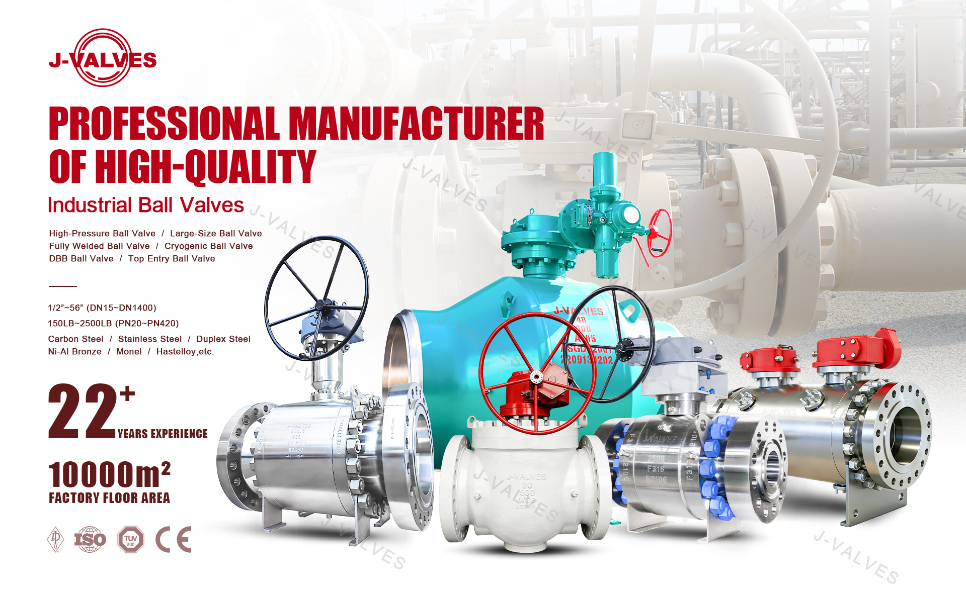
A pneumatic trunnion ball valve is a quarter turn isolation valve in which the ball is held on upper and lower trunnion bearings and rotated 90 degrees by a compressed air actuator. J-VALVES builds this version with a forged steel body, flanged ends to ASME B16.5 or ASME B16.47, a bore from DN50 to DN600 (2 to 24 inch) and a pressure range from Class 150 to Class 2500.
The pneumatic operator is usually the reason a buyer opens this page. On a line that must be opened and closed from a control room, on a fixed cycle, or on an emergency shutdown signal, a manual gear operator is too slow and an electric actuator is expensive to cycle several times an hour. Air does the same work with a smaller frame, a lower price and a spring that closes the valve when the air or the signal is lost.
The sections below cover the body and seat design, the actuator sizing logic, the material and test envelope, the applications where the combination pays for itself, and the data needed to quote the valve.
Why Air Instead of a Gear or an Electric Motor
Trunnion mounting and pneumatic actuation fit each other for one practical reason. A trunnion ball valve carries the ball on bearings, so line pressure does not press the ball into the seat and the operating torque stays almost flat across the pressure range. A flat torque curve means the actuator can be sized from a single number instead of a worst case, which keeps the actuator frame small, the air consumption low and the price down.
A floating ball valve at the same bore and class has a seat load that rises with the square of pressure. Its torque climbs steeply, so the actuator has to be oversized for the top of the range even though the valve spends most of its life at a lower pressure. That is one reason large floating ball valves above Class 300 are rarely automated.
A pneumatic actuator also brings a fail-safe action at no extra cost. A spring return unit holds the valve open or closed with no air and no power, which is exactly what an ESD loop, a fire signal or a compressor trip needs. An electric actuator needs a battery or a UPS to do the same, and both are a maintenance item that fails quietly.
Criterion | Pneumatic actuator | Electric actuator | Manual gear |
|---|---|---|---|
Initial cost | Lowest of the three | Highest | Lowest |
Cycle speed | 1 to 3 s for a 90 degree stroke | 10 to 60 s typical | Operator dependent |
Fail action on power loss | Spring return, no stored energy | Needs battery or UPS | Manual, on site |
High cycle duty | Preferred, no motor wear | Motor and brake wear | Not practical |
Position control | Open and closed, or modulating with a positioner | Full modulation | None |
Utility required | Clean dry air at 4 to 8 bar | Electrical supply | None |
Cold climate | Air dryer required | Enclosure heater required | None |
Best fit | ESD, batch, frequent cycling | Remote sites without air, modulation | Isolation only |
The trade-off is the air supply. A pneumatic package needs clean, dry instrument air at 4 to 8 bar. Wet or oily air destroys the seals and the solenoid, and a plant without a dryer will spend the savings on actuator seal kits. Where no instrument air exists and the line is remote, an electric actuator is the better answer, and we say so rather than sell the wrong package.
Body, Ball and Seat Construction
Forged body and split joint
The body is a two piece or three piece bolted split design forged from A105 carbon steel, with LF2 for low temperature, A182 F316 for corrosive duty and F51 duplex for chloride and sour service. Forging is specified rather than casting at Class 900 and above, and for bores below DN100, because a forged body has no shrinkage porosity, a finer grain flow and a wall that holds pressure without the extra thickness a casting needs. Above DN600 the economics reverse and a cast body is the sensible choice.
The body joint uses a spiral wound stainless and graphite gasket. Class 900 and above can be supplied with an RTJ ring joint to ASME B16.20 where the piping specification calls for it. Body bolts are A193 B7 with A194 2H nuts, zinc flake coated, and are torqued to a controlled procedure with the value recorded on the test sheet.
Trunnion bearings and ball support
The ball is fixed between an upper and a lower trunnion. On sizes DN100 and below both trunnions sit in the primary body; on DN150 and above they sit in separate bearing blocks bolted to the body. The trunnions run in metal backed, PTFE lined self-lubricating bearings, and a thrust washer takes the axial load so the ball cannot lift under pressure. Because the bearings carry the side load, the stem only transmits torque and never sees bending, which is why the stem can stay small and the operating torque stays repeatable after years in service.
The ball is A182 F316 with electroless nickel plating as standard. ENP lowers friction and resists galling against the seat, and it is the reason a DN200 Class 600 valve can still be turned by a modest actuator. Hard chrome and Stellite overlay are available where the fluid carries sand or scale.
Spring loaded seats
Two independent seat rings seal against the ball, one upstream and one downstream, so the valve is bidirectional. A ring of coil springs between each seat and the body pushes the seat onto the ball, which gives a seal at low or zero line pressure; as line pressure rises, the piston effect adds to the spring force and the seal tightens through the full range.
The seat type decides how the body cavity behaves, and this is the part most specifications get wrong.
Seat type | Seals both directions | Body cavity | Double block and bleed | Typical use |
|---|---|---|---|---|
Single piston effect (SPE) | Yes | Self relieving to the low pressure side | Yes | General process duty where thermal expansion of trapped fluid must vent itself |
Double piston effect, DIB-1 | Yes | Requires an external relief device | Yes | High pressure, toxic or flammable fluid, welded body valves |
Combined SPE x DPE, DIB-2 | Yes | Self relieving one side only | Yes, preferred direction | Where both cavity relief and a double barrier are required |
A DPE seat seals with pressure from either side, so if the upstream seat is damaged the downstream seat still holds. The price is that trapped fluid expanding in the cavity has nowhere to go, so the cavity must be protected by a relief valve or a rupture disc. An SPE seat vents that expansion back into the line by itself but gives up the double barrier. Choosing between them is a process safety decision, not a commercial one, and we ask for the line specification before quoting.
Every seat ring carries a sealant injection fitting. If solids, scale or wire damage the primary seal, sealant can be pumped into the seat groove to restore tightness until the next planned shutdown. The fitting is a needle valve with a non-return check, screwed into the body and connected to the seat ring.
Stem, sealing and fire safe behaviour
The stem is separate from the ball and is retained by the body cover, so it cannot be blown out by line pressure even if the gland is fully removed. Sealing is a triple barrier: two O-rings plus a graphite packing ring, which also provides the fire safe seal when the elastomer is destroyed. The upper O-ring can be replaced with the valve in line and the cavity vented, which turns a stem leak into a short job instead of a line shutdown.
An anti-static device connects ball, stem and body, keeping electrical continuity below 10 ohm so a static charge cannot build up in a flammable service. The mounting pad is machined to ISO 5211 with a square or keyed drive, so a pneumatic actuator, a gearbox or an electric actuator all fit the same valve without an adapter plate.
Fire safe behaviour follows API 607 and ISO 10497, with API 6FA available on request. If a fire destroys the soft seat insert, the metal seat ring seats against the ball and the graphite stem seal holds, so the valve keeps a barrier until the line can be depressurised.
Actuator Package and Torque Sizing
An actuator is sized on break torque, the torque needed to lift the ball off the seat after a period closed, not on running torque. Break torque can be two to three times running torque on a soft seated valve that has been sitting in dirty service, so the usual practice is to take the calculated break torque and apply a safety factor of 1.3 to 1.5, then check that the spring return unit still produces enough torque at the minimum site air pressure.
Air pressure matters more than most data sheets admit. A rack and pinion actuator rated at 8 bar loses roughly a quarter of its output at 5 bar, and a spring return unit loses more again on the spring stroke because the springs are being compressed. If the plant air header sags to 4.5 bar in the afternoon, an actuator sized at 7 bar will stall. We size spring return units at the lowest stated air pressure, not the nominal one.
Valve size | Class 150 | Class 300 | Class 600 | Class 900 | Class 1500 | Class 2500 |
|---|---|---|---|---|---|---|
DN50 (2 inch) | 55 | 75 | 110 | 160 | 220 | 340 |
DN80 (3 inch) | 90 | 130 | 190 | 270 | 380 | 560 |
DN100 (4 inch) | 140 | 200 | 300 | 420 | 600 | 880 |
DN150 (6 inch) | 280 | 400 | 600 | 850 | 1200 | 1800 |
DN200 (8 inch) | 450 | 650 | 980 | 1400 | 2000 | 2900 |
DN300 (12 inch) | 950 | 1350 | 2000 | 2900 | 4200 | 6100 |
DN400 (16 inch) | 1600 | 2300 | 3400 | 4900 | 7000 | 10200 |
DN600 (24 inch) | 3200 | 4600 | 6800 | 9800 | 14000 | 20000 |
Figures are indicative break torque in Nm for a soft seated valve at ambient temperature, with clean fluid and full pressure differential across the closed valve. Add the safety factor, then confirm against the final seat and trim selection. Do not use this table as a substitute for a torque calculation on abrasive, high temperature or dry gas duty.
The standard package pairs the valve with a rack and pinion actuator, a Namur solenoid valve and a filter regulator. A limit switch box, an air set with gauge, a speed control valve on each exhaust port and a declutchable manual override are added as the application requires.
Item | Standard | Option |
|---|---|---|
Actuator type | Rack and pinion, double acting | Scotch yoke, spring return |
Air supply | 4 to 8 bar, ISO 8573-1 class 3 air | 3 bar low pressure, 10 bar high pressure |
Rotation | 90 degrees, plus or minus 5 degrees adjustable | 120 or 180 degree |
Actuator body | Anodised aluminium | SS316, epoxy coated |
Sealing | NBR | Viton, silicone |
Ambient temperature | -20 to +80 °C | -40 to +150 °C |
Protection | IP66 and IP67 | ATEX II 2G Ex d IIB T4 |
Control | Namur 5/2 solenoid, 24 VDC or 220 VAC | Positioner, ESD relay, SIL 3 loop |
Feedback | Mechanical position indicator | Two SPDT limit switches, 4 to 20 mA |
Stroke time | 1 to 3 s at full air | Adjustable with exhaust flow controls |
Material Options
Component | Standard | Upgrade | Service notes |
|---|---|---|---|
Body | A105 forged carbon steel | LF2, A182 F316, F51 duplex | Forging preferred at Class 900 and above, and below DN100 |
Ball | A182 F316 with ENP | F304, hard chrome, Stellite overlay | ENP lowers torque and resists galling |
Stem | A182 F316 with ENP | F51, 17-4PH | Blow-out proof, anti-static connected |
Seat ring | A182 F316 | F51, Inconel 625 | Carries the sealant injection port |
Seat insert | RPTFE | PTFE, PEEK, nylon, metal to metal | Temperature and fluid driven |
Stem seal | Graphite plus two O-rings | PTFE lip seal | Triple barrier, fire safe backup |
Body gasket | Spiral wound SS316 with graphite | RTJ ring joint to ASME B16.20 | RTJ used at Class 900 and above |
Bolting | A193 B7 with A194 2H | A320 L7 for low temperature | Zinc flake coated |
Actuator body | Anodised aluminium | SS316, epoxy coated | Marine and offshore duty |
The seat insert is the part that sets the temperature limit. RPTFE covers -29 to +180 °C and most water, oil and gas duty. PEEK extends the upper limit and tolerates steam and aromatics. Nylon is used where a tighter low pressure seal is needed at moderate temperature. Metal to metal seating is specified for abrasive slurries and for fire exposed duty where no polymer may remain, and it is supplied with a lapped and hardened ball.
For sour service the wetted parts are supplied to NACE MR0175 and ISO 15156 with hardness controlled and verified per heat number, and the certificate records the results. For offshore and chloride bearing streams F51 duplex is the usual body choice because it resists chloride stress corrosion cracking at a yield strength carbon steel cannot reach.
Technical Specifications
Item | Standard build | Optional |
|---|---|---|
Nominal size | DN50 to DN600 (2 to 24 inch) | DN15 to DN40 on request |
Pressure class | ASME Class 150, 300, 600, 900, 1500, 2500 | PN16 to PN420 |
Body material | A105 forged carbon steel | LF2, A182 F304, F316, F51 |
Ball and stem | A182 F316 with ENP | F304, hard chrome, Stellite |
Seat insert | RPTFE, spring loaded | PTFE, PEEK, nylon, metal to metal |
Seat type | Single piston effect (SPE) | DPE (DIB-1), combined SPE x DPE (DIB-2) |
End connection | Flanged RF to ASME B16.5 | RTJ, hub, butt weld to ASME B16.25 |
Face to face | API 6D and ASME B16.10 | Special length to drawing |
Bore | Full bore, API 6D Table 1 | Reduced bore |
Temperature range | -29 to +180 °C | -46 °C low temp, +200 °C PEEK, -196 °C cryogenic |
Operation | Double acting pneumatic | Spring return, gear, electric, gas over oil |
Air supply | 4 to 8 bar, dry and filtered | 3 bar low pressure version |
Leakage class | API 598, ISO 5208 Rate A | Rate B for metal seated |
Design standard | API 6D and ISO 14313, ASME B16.34 | EN 12516, GB/T 12237 |
Fire safe | API 607 and ISO 10497, API 6FA | - |
Anti-static | Fitted as standard | - |
Documentation | EN 10204 3.1 material certificate | PED 2014/68/EU, ATEX, SIL 3 |
Standards and Compliance
Requirement | Standard | Supplied |
|---|---|---|
Valve design | API 6D and ISO 14313 | Yes |
Wall thickness | ASME B16.34 | Yes |
Face to face | API 6D, ASME B16.10 | Yes |
Flange drilling | ASME B16.5, ASME B16.47 | Yes |
Weld end preparation | ASME B16.25 | Optional |
Pressure and seat test | API 598 | Yes |
Fire safe test | API 607, ISO 10497, API 6FA | Yes |
Anti-static test | API 6D annex | Yes |
Sour service material | NACE MR0175, ISO 15156 | Optional |
Fugitive emission | ISO 15848-1 | Optional |
Actuator interface | ISO 5211, Namur VDI/VDE 3845 | Yes |
Functional safety | IEC 61508, SIL 3 capable | Optional |
Material certificate | EN 10204 3.1 or 3.2 | Yes |
European pressure equipment | PED 2014/68/EU | Optional |
The actuator interface deserves a note because it is the detail that decides whether a spare actuator fits. The mounting flange and drive are machined to ISO 5211, and the solenoid and switch box ports follow Namur VDI/VDE 3845. That means an off the shelf actuator, a positioner or a switch box from any major supplier will bolt on without an adapter, and a replacement can be sourced locally instead of from us.
Testing and Quality Control
Every valve passes a ten step inspection sequence, and each step is recorded so the test report, the material certificates and the torque record form one document package tied to the order.
Step | What is checked | Acceptance |
|---|---|---|
1 Incoming material | Heat number, chemistry, mill certificate | EN 10204 3.1, traceable |
2 Forging and NDT | Ultrasonic and magnetic particle on body | ASTM A788, no relevant defect |
3 Machining | Bore, seat pocket, face to face, concentricity | ASME B16.10, drawing |
4 Assembly | Bolt torque, spring load, sealant port | Procedure, no bind |
5 Shell test | 1.5 times rated pressure, water | API 598, no leak |
6 Seat test | 1.1 times rated pressure, both directions | API 598, ISO 5208 Rate A |
7 Anti-static and torque | Resistance, break and run torque | API 6D, values recorded |
8 Actuator function | Stroke time, fail action, limit switch setting | Customer specification |
9 Coating and marking | Dry film thickness, nameplate, heat number | Specification, legible |
10 Final and documents | Visual, packing, document set | Complete before shipment |
The shell test holds the body at 1.5 times the rated pressure with water while every joint is watched for weeping. The seat test applies 1.1 times the rated pressure to each seat in turn, in both flow directions, and measures leakage against the ISO 5208 rate agreed on the order. The anti-static test measures resistance from ball to body and must stay below the limit in API 6D. Torque is measured on the assembled valve and the figure is written into the test report, so the next actuator on that valve can be sized from a real number.
Applications
Industry | Duty | Why the pneumatic version |
|---|---|---|
Oil and gas gathering | Wellhead and manifold isolation | ESD signal closes the valve with no power available |
Refining and petrochemical | Feed, product and utility isolation | Fast cycling from the DCS, instrument air already on site |
Gas processing and LNG | Dryer and molecular sieve switching | 1 to 3 s stroke on a short repeating cycle |
Water and wastewater | Pump discharge and header isolation | Low cost per cycle, no motor heat in a wet pit |
Power generation | Cooling water, fuel gas, soot blower | Spring return fail-safe on a unit trip |
Chemical | Acid, solvent and slurry lines | Remote operation away from the hazard |
Marine and offshore | Cargo and ballast isolation | Compact frame, ATEX package, duplex body option |
Mining and slurry | Tailings and process water | Frequent cycling with a PEEK or metal seat |
The pattern across these duties is the same. The valve is not there to throttle, it is there to isolate, and it has to do so quickly and repeatably without an operator walking to the line. Where the cycle count is high, the pneumatic package wins on cost per cycle. Where the line is unmanned and has no air, the electric actuator wins, and we will recommend it.

Installation, Commissioning and Maintenance
Store the valve with flange protectors fitted, in the open position, on a dry floor. Do not lift by the actuator or the solenoid.
Clean the flange faces and the bore before fitting, and check that the ball is in the open position so the seat is not damaged during make up.
Torque the flange bolts in a cross pattern to the gasket supplier value. Support valves above DN300 independently so the pipe does not carry the actuator weight.
Blow the air line through before connecting. Fit a 5 micron filter regulator within a few metres of the actuator, and use dry air to ISO 8573-1 class 3.
Set the open and close stops to within one degree of the required position, then lock them. Over-travel is the most common cause of a damaged seat insert on a new installation.
Adjust stroke time with the flow control valves on the exhaust ports, not by throttling the supply, which starves the actuator and slows the last part of the stroke.
Test the fail action before the line is pressurised. Trip the air and confirm the spring drives the valve to the safe position within the specified time.
Cycle the valve five times dry, then pressure test the joints at operating pressure and check the seat for leakage.

In service, the items that need attention are the air set, the solenoid coil and the seat. Drain the filter bowl on schedule; a bowl full of water is the first sign of a dryer problem upstream. If a seat begins to pass, inject sealant through the fitting in small strokes until the leakage stops, and record the quantity, because a seat that needs sealant twice in a year is due for replacement. Replace the actuator seal kit every two to three years, or sooner in a hot or dusty location. Check the anti-static bond at each shutdown and re-torque the body bolts to the procedure if the joint has been opened.
How to Specify and Order
A complete enquiry needs nine pieces of information, and the ordering code below captures all of them in one line.
Position | Meaning | Options |
|---|---|---|
1 | Series | JV-PT pneumatic trunnion |
2 | Size | DN50 to DN600 |
3 | Class | 150, 300, 600, 900, 1500, 2500 |
4 | Body material | A105, LF2, F316, F51 |
5 | Seat insert | R RPTFE, P PTFE, K PEEK, M metal |
6 | Bore | F full, R reduced |
7 | Actuator action | DA double acting, SR spring return |
8 | Fail position | FC fail closed, FO fail open |
9 | Accessories | S solenoid, L limit switch, P positioner, F filter regulator |
An example: JV-PT-100-300-A105-K-F-SR-FC-SL is a 4 inch Class 300 valve, forged A105 body, PEEK seat, full bore, spring return actuator failing closed, with a solenoid valve and a limit switch box.
Along with the code, state the fluid, the design temperature, the pressure differential across the closed valve, the air supply pressure available at the actuator, the fail action required, and whether NACE, ATEX, SIL or PED documentation is needed. If the line specification calls for a seat type, quote it; if not, we will recommend SPE or DPE based on the fluid and the cavity relief arrangement.
Standard specifications ship in 2 to 4 weeks from one piece. The document package contains the EN 10204 3.1 material certificate, a dimensional report, the pressure and seat test report with torque values, the actuator function record, a coating report and a packing list. Third party inspection can be arranged at any stage, and the witnessed results are added to the package. Export packing uses a wooden case with the bore plugged, the flange faces protected and the actuator braced so it cannot move in transit.
FAQ
Q: What is the difference between a pneumatic trunnion ball valve and a pneumatic floating ball valve?
A: In a floating ball valve the ball is held only by the seats, so line pressure pushes it downstream and the seat load and torque rise steeply with pressure. In a trunnion valve the ball is fixed on upper and lower bearings, so the body carries the load, the torque stays nearly flat across the pressure range and the actuator can be sized smaller. Above Class 300 and DN150 the trunnion design is normally the cheaper package once the actuator is included.
Q: What air pressure does the actuator need, and what happens if the air supply fails?
A: Standard actuators run on 4 to 8 bar of clean dry air. A double acting unit holds its last position when air is lost, because the trapped air locks the pistons. A spring return unit drives the valve to the fail position, closed or open as specified, with no air and no electrical power. We size spring return units at the lowest air pressure stated for the site, not at the nominal 7 bar, so a sagging header does not stall the stroke.
Q: Can the valve be supplied for emergency shutdown service with SIL 3?
A: Yes. The pneumatic package can be supplied with an ESD solenoid, a partial stroke test function and a SIL 3 capable loop using an actuator and solenoid with IEC 61508 certification. The valve itself contributes a proven failure rate from the API 6D test record. Provide the required safety integrity level, the proof test interval and the fail action so the loop can be assessed as a whole.
Q: What is the largest size available with a forged steel body?
A: Forged A105 bodies are supplied up to DN600 (24 inch). Above that size a cast body is the practical choice on weight and cost, and it is covered by our cast steel trunnion range. The original page on our website quoted 2 to 56 inch for the whole trunnion family, which mixes forged and cast sizes; the forged pneumatic version in this page is DN50 to DN600.
Q: How do I calculate the actuator torque for my line conditions?
A: Start from the break torque for the size and class, apply a safety factor of 1.3 to 1.5, then check that the selected actuator still delivers that torque at the minimum air pressure available. Add margin for dry gas, abrasive solids, high temperature and long idle periods closed, because all four raise break torque. Send the fluid, temperature, differential pressure and air supply and we will return the calculation with the quotation.
Hot Products


News
Sanitary Clamp Ball Valves: 3-A, FDA And CIP Design Requirements
A sanitary clamp ball valve is not a polished standard valve. Cavity, seat wiping, Ra, drainability and 3-A paperwork decide whether it survives CIP.
Read More
Slurry Ball Valve Selection: Wear, Velocity, Seats And Materials
1. Slurries do not wear valves out; velocity doesA ball valve in clean water service can run for twenty years. The same valve in a 30 percent solids tailings line can be scrap in four months, and the difference is almost never the pressure class or the body material. Abrasive wear scales roughly wit
Read More
Fire-Safe Ball Valve Design: The Metal Backup Seat Behind API 607
How a fire-safe ball valve survives API 607: the metal backup seat, graphite packing and body joint that keep sealing after the soft parts burn.
Read More
Metal Seated Ball Valve: Clearance, Thermal Growth And Leakage Class
Metal-seated ball valves seal on hardfaced contact, not polymer: how clearance, differential growth and seat spring load set the leakage class.
Read More