
CHINA J-VALVES Offers Various High-quality I ndustrial Ball Valves
J-VALVES, a distinguished professional ball valve manufacturer rooted in China, takes pride in its extensive product portfolio. Our offerings span a wide range, including trunnion-mounted ball valves, floating ball valves, high-temperature ball valves, high-pressure ball valves, metal-sealed ball valves, ultra-low temperature ball valves, DBB ball valves, Three-way And Four-way Ball Valve, and fully welded ball valves. Each product is a testament to our commitment to precision engineering and reliable performance. Meticulously crafted, they are designed to not only meet but exceed the most stringent industrial demands, ensuring stable operation even under extreme conditions. This enables us to provide our clients with high-value services and makes our valves widely sought-after in industries.
Product Category
Contact Us


Pressure Rating: 1000 PSI WOG (6.9 MPa), PN64 metric nameplate
Port Design: Full port, bore equal to pipe inside diameter
Body Material: CF8 304, CF8M 316, CF3 304L, CF3M 316L investment cast
Ball and Stem: CF8M 316, solid ball lapped to Ra 0.2-0.4 um
Seat Material: PTFE, RPTFE, PPL, PEEK or metal to metal
Body Seal: PTFE standard, graphite for fire safe duty
End Connection: Butt weld to ASME B16.25, 37.5 degree bevel
Face to Face: ASME B16.10 / GB/T 12221
Design Standard: ASME B16.34, GB/T 12237
Test Standard: API 598, shell 1.5x and seat 1.1x rated pressure
Temperature Range: -20 C to +200 C PTFE, +250 C PPL, +260 C PEEK, +300 C metal seat
Operation: Lever with locking device, ISO 5211 mounting pad optional
Certification: EN 10204 3.1 material certificate, ISO 9001, CE/PED on request
-
Q11F
-
J-VALVES
What Is a Stainless Steel Three-Piece Butt Weld Ball Valve?
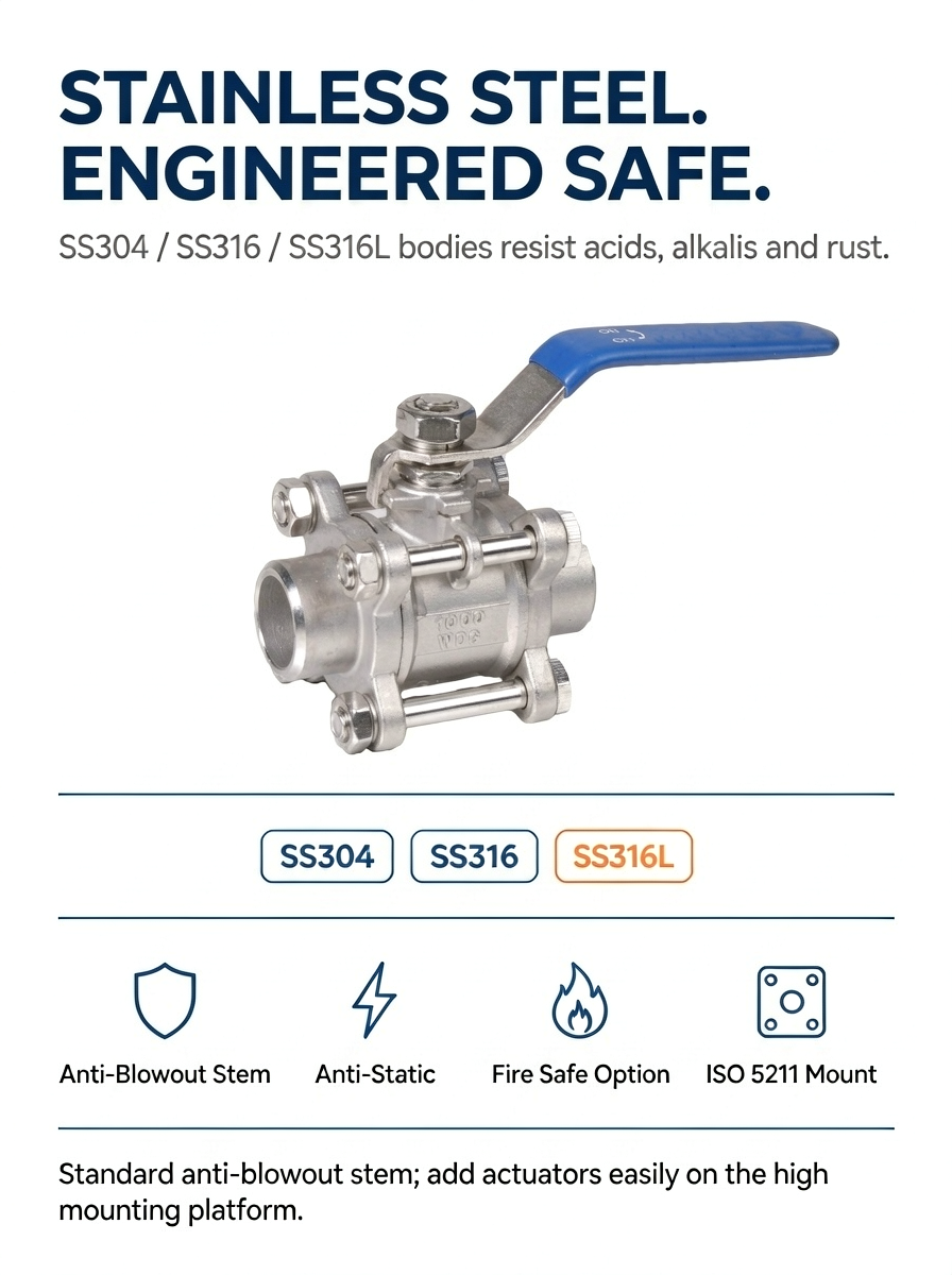
Direct answer: a stainless steel three-piece butt weld ball valve is a quarter-turn isolation valve whose body is split into a centre section and two weld-end tailpieces, clamped by four or more body bolts. The centre section carries the ball, seats and stem and swings out sideways, so worn seats and body seals can be replaced in the line without cutting the pipe. The J-VALVES Q61F series covers 1/4 inch to 4 inch (DN8 to DN100), full port, 1000 PSI WOG (6.9 MPa), in CF8 304, CF8M 316, CF3 304L or CF3M 316L investment cast stainless steel.
Key facts at a glance
Item | Value |
|---|---|
Model code | Q61F-64P (304), Q61F-64R (316), Q61F-64RL (316L) |
Size range | 1/4 inch to 4 inch (DN8 to DN100) |
Pressure rating | 1000 PSI WOG, 6.9 MPa, PN64 metric nameplate |
Port | Full port, bore equal to pipe inside diameter |
Body | CF8, CF8M, CF3 or CF3M investment cast stainless |
Ball and stem | CF8M 316, solid ball lapped to Ra 0.2-0.4 um |
Seat | PTFE standard, RPTFE, PPL, PEEK or metal optional |
End connection | Butt weld to ASME B16.25, 37.5 degree bevel |
Temperature | -20 to +200 °C on PTFE, +260 °C on PEEK, +300 °C on metal seat |
Testing | API 598, shell 1.5x and seat 1.1x, on 100 percent of production |
Repair | In line, centre section swings out after removing four bolts |
Why Three-Piece Construction Suits a Welded Stainless Line
The distinction that matters between a one-piece, a two-piece and a three-piece ball valve is not the parts count. It is what happens on the day a seat wears out.
In a one-piece or two-piece valve welded into a stainless line, a passing seat means cutting the pipe, and on a hygienic or high purity line that means re-purifying the whole spool afterwards. A three-piece valve needs four body bolts loosened. The centre section lifts out sideways between the two tailpieces, the seats and body seals are replaced on the bench, and the valve goes back into the same welded tails. No hot work, no re-test of the pipe weld, no shutdown of the rest of the line.
That serviceability is also why the three-piece body costs more than a two-piece. Two extra machined joint faces, two body seals and a longer bolt pattern all add machining time and a second leak test. The return is that the valve becomes a serviceable component instead of a consumable one.
The cost of that flexibility is two additional body joints. Each joint carries a PTFE or graphite body seal that has to be compressed to a set torque: too little and the joint weeps at pressure, too much and the seal extrudes into the bore and the ball drags. Every J-VALVES three-piece valve ships with a marked torque value and a diagonal two-stage tightening sequence, and the figure should be taken from the nameplate rather than from a general table, because the correct value changes with size, bolt grade and gasket material.
The Butt Weld Advantage, and the Weld Heat Problem It Creates
Butt weld ends machined to ASME B16.25 remove two leak paths that a threaded joint introduces. There is no thread root to trap moisture and start crevice corrosion, no sealant tape to degrade, no galling between stainless male and female threads, and no helical gap for bacteria to colonise on a hygienic line. A welded joint also weighs 30 to 40 percent less than the flanged equivalent at the same bore, which matters on a skid or an offshore module where every kilogram is carried by structure.
The trade-off is heat. A welding arc sits above 1500 °C within 100 mm of a PTFE seat that starts to degrade above 260 °C and melts at 327 °C. Heat conducts along the stainless tailpiece straight into the seat pocket. This is the single most common reason a soft seated weld-end ball valve fails its first pressure test after installation, and most catalogue pages mention the risk without offering a way out of it.
Three-piece construction provides the way out, and this is the strongest technical argument for choosing it. Unbolt the centre section first. Weld both tailpieces to the pipe with nothing but stainless steel inside them. Let them cool to ambient. Then bolt the ball, seats, stem and body seals back in. No seat, no body seal and no stem packing ever sees welding heat, so the full temperature rating of the valve survives installation intact.
A two-piece valve cannot be treated this way, because its single body joint does not allow the trim to come out without disturbing the welded end. That is the practical reason a three-piece valve is the correct specification for a welded stainless line, and it is worth stating in the quotation, because it changes the installation sequence on site.
When site conditions force the valve to be welded fully assembled, in small sizes or on a tie-in that cannot be broken, the seat material has to carry the heat. In that case specify PPL, PEEK or a metal seat rather than PTFE, wrap the body in a wet cloth, hold the interpass temperature at or below 150 °C measured 25 mm from the weld, and use the lowest heat input the procedure allows. The valve will survive, but part of the seat life is spent before the line is even pressurised.
Reading the Model Code: Q61F, Not Q11F
Chinese and most Asian valve catalogues encode the type in the model number, and reading it correctly is the fastest way to confirm what a quotation actually offers. For a ball valve the first letter is Q. The second digit gives the end connection: 1 is internal thread, 4 is flange, 6 is weld end. The third digit gives the ball arrangement: 1 is floating, 7 is trunnion mounted. The letter after that gives the seat material: F is the PTFE family, H is Cr13 stainless, Y is a hard alloy. The number after the hyphen is the nominal pressure, and the trailing letter gives the body material, where P is CF8, R is CF8M and RL is CF3M.
On that reading, a butt weld floating ball valve with a PTFE seat and a 316 body is Q61F-64R. Q11F, which appears on many listings for this product, is the threaded version of the same design, because the 1 in the second position means internal thread. The two valves share a ball, a stem and a seat, but they are not interchangeable on a purchase order, and quoting Q11F against a weld-end requirement is a documentation error that only surfaces at goods receipt.
Code | End connection | Ball | Seat | Rating | Body |
|---|---|---|---|---|---|
Q11F-16P | Internal thread | Floating | PTFE | PN16 | CF8 304 |
Q41F-16R | Flange | Floating | PTFE | PN16 | CF8M 316 |
Q61F-64R | Butt weld | Floating | PTFE | PN64 / 1000 WOG | CF8M 316 |
Q61F-64RL | Butt weld | Floating | PTFE | PN64 / 1000 WOG | CF3M 316L |
Q67F-64R | Butt weld | Trunnion | PTFE | PN64 | CF8M 316 |
Design and Construction
Ball
The ball is a solid CF8M casting rather than a hollow shell, and the through bore is machined to match the pipe inside diameter so the valve adds no measurable pressure drop. The sealing surface is lapped to Ra 0.2 to 0.4 um and then matched to its own seat pair during assembly, which is why balls and seats are supplied as a set rather than as loose parts. Hard chrome or electroless nickel is available where the medium carries fine abrasive solids.
Stem and anti-static path
The stem is bottom loaded from inside the body, so line pressure cannot blow it out even with the gland removed. Two O-rings backed by a PTFE thrust washer carry the stem seal, and a spring loaded anti-static device keeps the ball, stem and body in electrical contact, typically below 10 ohm, so a static charge from a fast flowing hydrocarbon cannot build up on the ball.
Seat options
The seat sets the real service limit of this valve. PTFE is standard and covers most water, oil and gas duty to 200 °C. RPTFE, reinforced with 15 to 25 percent glass or carbon, raises the allowable pressure-velocity product and reduces cold flow under sustained load. PPL takes the ceiling to about 250 °C and is the usual choice when the valve will be welded fully assembled. PEEK reaches 260 °C and above with better abrasion resistance. A metal seat with a hard faced insert covers abrasive slurries and the highest temperatures, at the cost of a lower leakage class.
Body seals and bolting
Standard body seals are PTFE gaskets seated in machined grooves. For fire safe duty the gaskets are graphite with a metal backup, so the joint still seals after a fire has destroyed the soft material. Body bolts are A2-70 stainless as standard and A4-70 for marine and chloride service. They are not re-used after a seat change, because a stretched bolt cannot reproduce the original joint load.
Operator interface
The lever is a 304 flat bar with a vinyl grip, a 90 degree stop and an optional padlockable locking device for lockout-tagout. A high platform version with an ISO 5211 mounting pad is available where a pneumatic or electric actuator will be fitted, and the pad can be machined at the time of order so the actuator bolts on without an adapter plate.
Material Selection: 304, 316, 304L or 316L
All four grades are austenitic stainless steels of similar strength, so the choice is driven by corrosion rather than by pressure. 304 (CF8) is adequate for potable water, neutral process water and general industrial service. 316 (CF8M) adds 2 to 3 percent molybdenum, which is what gives it resistance to chlorides, marine atmosphere, most organic chemicals and the dilute acids found in dosing systems.
The L grades exist for a reason that matters more on this valve than on a threaded one. Welding holds the heat affected zone between roughly 425 °C and 815 °C long enough for chromium carbides to precipitate at the grain boundaries. The metal immediately beside those carbides is left chromium depleted and becomes anodic, so the weld decay zone corrodes preferentially even in a mildly aggressive medium. A low carbon grade, with a maximum of 0.03 percent carbon, has too little carbon available to form those carbides. Because a butt weld valve is welded directly into the line, 316L is the safer default for chemical, food, beverage and pharmaceutical duty even though 316 has slightly higher nominal strength.
Chloride stress corrosion cracking is the other failure mode worth designing around. 304 is at risk in chloride bearing water above about 60 °C; 316 tolerates a higher temperature but is not immune. Above roughly 80 °C in a concentrated chloride environment a duplex body is the correct answer rather than a higher austenitic grade.
Grade | Cast equivalent | Best for | Avoid when |
|---|---|---|---|
304 | CF8 | Potable water, neutral process water, general industry | Chlorides above 60 °C, marine air, chemical dosing |
316 | CF8M | Chlorides, marine, most chemicals, food and beverage | Aggressive welded assemblies without post weld cleaning |
304L | CF3 | Welded lines in mildly corrosive service | Chloride service, higher strength demand |
316L | CF3M | Welded chemical, pharmaceutical and hygienic lines | Concentrated chloride above 80 °C |
Pressure Rating: What 1000 WOG Really Means
WOG stands for water, oil and gas, and it is a non-shock rating taken at ambient temperature. 1000 PSI WOG equals 69 bar or 6.9 MPa. It is a cold rating, and reading it as an allowable working pressure at 200 °C is the most common specification mistake made with soft seated valves.
The metric nameplate on the same valve is usually PN64, which is 6.4 MPa. That is about 7 percent below the imperial figure, so a valve dual marked 1000 WOG and PN64 is rated by the lower number whenever the metric class is used. The difference is small and the practice is conservative, but it should be stated rather than left for the buyer to discover, which is exactly the ambiguity that appears in most listings for this product.
Body wall thickness follows ASME B16.34 and is not the limiting element at these sizes. The seat is. The table below gives typical derating by seat material; confirm the final figure against the order drawing, because the curve shifts slightly with size and with the specific compound used.
Temperature | PTFE seat | PPL seat | PEEK seat | Metal seat |
|---|---|---|---|---|
-20 °C | 1000 PSI | 1000 PSI | 1000 PSI | 1000 PSI |
38 °C | 1000 PSI | 1000 PSI | 1000 PSI | 1000 PSI |
93 °C | 800 PSI | 900 PSI | 950 PSI | 1000 PSI |
150 °C | 600 PSI | 750 PSI | 850 PSI | 1000 PSI |
200 °C | 400 PSI | 620 PSI | 750 PSI | 980 PSI |
250 °C | Not suitable | 500 PSI | 700 PSI | 950 PSI |
300 °C | Not suitable | Not suitable | 600 PSI | 900 PSI |
Two practical consequences follow. First, a 1000 WOG valve on a 180 °C hot water line is really a 450 PSI valve, so a line rated at 25 bar is fine and a line rated at 40 bar is not. Second, the derating is a seat property and not a body property: the same body with a PEEK seat holds 750 PSI at 200 °C where the PTFE version holds 400 PSI. Upgrading the seat is usually cheaper than upgrading the whole valve.
Flow Capacity and Operating Torque
Full port means the bore matches the pipe inside diameter, so the valve behaves as a straight length of pipe and the pressure drop across it is negligible in the turbulent range. That is why the Cv of a full port valve is set by the line size rather than by the valve design, and why a reduced port valve of the same nominal size delivers only 60 to 70 percent of the figures below.
Size | DN | Bore | Cv (water) | Breakaway torque at 1000 PSI |
|---|---|---|---|---|
1/4 inch | DN8 | 6.4 mm | 5.5 | 8 Nm |
3/8 inch | DN10 | 9.5 mm | 8 | 10 Nm |
1/2 inch | DN15 | 12.7 mm | 14 | 16 Nm |
3/4 inch | DN20 | 19 mm | 25 | 24 Nm |
1 inch | DN25 | 25 mm | 42 | 38 Nm |
1-1/4 inch | DN32 | 32 mm | 68 | 55 Nm |
1-1/2 inch | DN40 | 38 mm | 100 | 78 Nm |
2 inch | DN50 | 50 mm | 175 | 120 Nm |
2-1/2 inch | DN65 | 65 mm | 280 | 175 Nm |
3 inch | DN80 | 76 mm | 420 | 230 Nm |
4 inch | DN100 | 100 mm | 750 | 360 Nm |
Torque figures are breakaway values at full rated differential with a PTFE seat at ambient temperature, which is the number an actuator has to overcome. Two corrections are normally applied when sizing: multiply by 1.3 to 1.5 as a safety factor, and add margin if the medium is above 100 °C or carries solids. A valve that turns easily by hand at 20 °C can stall an undersized pneumatic actuator at 150 °C, because seat friction rises as the PTFE softens and the stem seal tightens.
One-Piece, Two-Piece and Three-Piece Compared
Feature | One-piece | Two-piece | Three-piece |
|---|---|---|---|
Body joints | None | One | Two, bolted |
Repairable in line | No | No | Yes |
Seat replacement | Replace the valve | Replace the valve | Replace seat and seal set |
Welded into a line | Cut out to service | Cut out to service | Tails stay, trim comes out |
Relative cost | Lowest | Middle | Highest |
Pressure integrity | Best, no body joint | Good | Good, two controlled joints |
Typical use | Economy isolation, small bore | General service, budget projects | Welded lines, hygienic, chemical, high cycle duty |
One-piece wins where the valve is cheap and the line is not critical. Two-piece wins on price in general service where the valve will be replaced rather than repaired. Three-piece wins whenever the cost of cutting a welded stainless line exceeds the price difference between the valve types, which is almost always the case above 1 inch.
End Connection Comparison
Property | Butt weld | Socket weld | Threaded | Flanged |
|---|---|---|---|---|
Leak paths at the joint | None after welding | One fillet, crevice at socket | Thread spiral, sealant dependent | Gasket, bolt creep |
Pressure integrity | Highest | High | Limited by thread | High |
Hygiene and CIP | Best, flush bore | Crevice traps product | Thread gap traps product | Gasket shadow |
Removal | Cut the weld | Cut the weld | Unscrew | Unbolt |
Weight at equal bore | Lowest | Low | Low | 30 to 40 percent heavier |
Best for | Process, hygienic, high cycle thermal | Small bore utility | Maintenance access, low pressure | Frequent dismantling, equipment isolation |
Standards and Compliance
The valve is designed to ASME B16.34 and GB/T 12237, with butt weld ends machined to ASME B16.25, face-to-face dimensions to ASME B16.10, marking to MSS SP-25 and pressure testing to API 598. Where a project requires it, the same valve can be built and documented to API 6D for pipeline duty, which adds a documented design package, a fire test to API 607 and full material traceability.
Requirement | Standard | Status |
|---|---|---|
Valve design | ASME B16.34, GB/T 12237 | Standard |
Butt weld ends | ASME B16.25 | Standard |
Face-to-face dimensions | ASME B16.10, GB/T 12221 | Standard |
Pressure testing | API 598, GB/T 13927 | Standard |
Marking | MSS SP-25 | Standard |
Material certificate | EN 10204 3.1 | Standard |
Fire safe | API 607 | Optional |
European pressure equipment | PED 2014/68/EU | Optional |
Quality system | ISO 9001 | Certified |
On the PED point, valves above DN25 with a pressure above 0.5 bar fall inside the directive and normally need a CE mark with Category I or higher documentation. Below DN25 the same valve can be placed on the market under Article 4.3, sound engineering practice, without a CE mark. Buyers who need the CE route on 1/2 inch and 3/4 inch sizes should raise it at enquiry stage, because the paperwork has to be prepared with the order and not after it.
Testing and Quality Control
Every valve is tested, not a sample from each batch. The shell test pressurises the assembled body with water at 1.5 times the rating, which is 1500 PSI, and holds it for 15 seconds up to DN50 and 60 seconds from DN65 to DN200 as API 598 requires, with all joints and the body wall inspected for weeping. Each seat is then tested separately at 1.1 times the rating, 1100 PSI, in both flow directions, and a soft seated valve also takes the low pressure closure test at 80 to 100 PSI air with the seat submerged, because a seat that holds at 1100 PSI can still bubble at 90 PSI if the preload is wrong.
Step | What is checked | Acceptance |
|---|---|---|
Incoming material | Heat number, chemistry, mill certificate | EN 10204 3.1, grade match |
Investment casting | Wall thickness, porosity, surface | Dimensional report, visual |
Machining | Bore, seat pocket, face to face, bevel angle | ASME B16.10, ASME B16.25, drawing |
Assembly and function | Body bolt torque, open-close, lever stop | Torque record, smooth travel |
Shell test | Body and both joints at 1.5x | API 598, no leak, no sweating |
Seat test | Each seat at 1.1x, both directions | API 598, no visible leak |
Low pressure closure | 80 to 100 PSI air, submerged | No continuous bubble |
Final and documents | Marking, caps, certificate package | MSS SP-25, 3.1 set complete |
The document package that travels with the goods contains the EN 10204 3.1 material certificate for every pressure retaining part with its heat number, a dimensional report, the pressure test report with the torque record, and a packing list. Third party inspection, positive material identification, radiography of the body casting or a witnessed test can be added at any of these stages when the order calls for it.

Welding Procedure: Installing Without Damaging the Seats
The installation sequence below is the one that protects the trim, and it is only possible because the body comes apart.
Confirm the pipe grade and the valve body grade, and select the filler metal. Use ER316L for 316 to 316 joints and ER309L for a stainless to carbon steel transition; ER316L in a dissimilar joint will crack.
Unbolt the centre section and set it aside in a clean bag. The two tailpieces are now plain stainless fittings with nothing heat sensitive inside them.
Machine or grind the pipe end to a 37.5 degree bevel with a 1.5 mm land, and clean 25 mm either side of the joint to bare metal.
Tack weld in four places, check alignment against ASME B31.3 for the applicable service, then complete the root pass.
Purge the bore with argon at 8 to 12 litres per minute and keep the internal oxygen below 100 ppm until the root is complete. Without purge the inside of the weld oxidises into a rough black scale that traps product and starts pitting, which is unacceptable on a hygienic or high purity line.
Complete the fill and cap passes with a heat input of 1.5 kJ/mm or less and an interpass temperature of 150 °C or less.
Let the tailpieces cool to ambient, then clean the bore, fit new body seals, and bolt the centre section back in using the marked torque and a diagonal two stage sequence.
Pickle and passivate the weld and the heat affected zone with a gel, leave 20 to 30 minutes, and rinse to a neutral pH. Do not flood the valve bore with acid.
Re-test the valve seats at 1.1 times the rating before the line is handed over, and record the result against the valve serial number.
If the valve has to be welded fully assembled, add a wet cloth wrap around the body, weld in short passes with cooling between them, and check the body temperature with a contact thermometer rather than by hand. Anything above 150 °C at 25 mm from the weld is eating seat life.
Maintenance and Seat Replacement
The valve is designed so that a seat change is a bench job rather than a workshop job. Isolate the line, depressurise and drain both sides, then cycle the valve to the half open position so the ball is clear of both seats.
Mark the centre section orientation relative to the tailpieces before loosening anything, so it goes back in the same clock position.
Loosen the body bolts in a cross pattern in two stages, and keep the bolts in order.
Lift the centre section out. Inspect the ball for scoring, the seat faces for extrusion or swelling, and the body seal grooves for corrosion.
Replace the seats, body seals and stem packing as a set. A new seat against a worn ball will leak again within weeks.
Clean the seal grooves, fit new gaskets dry, and check that no gasket overhangs into the bore.
Re-torque to the nameplate value in two diagonal stages, then cycle the valve four times and re-check the torque.
Re-test both seats at 1.1 times the rating before returning the valve to service, and record the new seat set in the maintenance log.
Applications
Water treatment and reverse osmosis skids use the 316 body because the concentrate stream is aggressive to 304, and the full port bore keeps the pressure drop low enough that the high pressure pump duty does not have to be re-rated. Food, beverage and brewery lines use the three-piece body for clean-in-place duty: the centre section comes out for inspection without breaking a hygienic weld, and the flush bore leaves no place for product to sit.
Pharmaceutical and high purity water systems specify 316L with a low ferrite weld and full passivation, because the weld is inside the product contact boundary and the surface finish is a validation item. Chemical dosing and acid transfer lines use PTFE or PEEK seats with a 316 body, and often add the locking lever because the valve is left in a fixed position for long periods.
Marine and offshore utility systems use A4-70 bolting and 316 bodies against salt atmosphere. Fire protection systems use the valve as a sectional isolation on sprinkler and deluge headers, where the locking lever in the open position and the full port bore both matter to the authority having jurisdiction. Cryogenic service is handled with an extended stem so the stem seal sits outside the cold zone, and the same body is used with a modified stem length.
Common Problems and How to Avoid Them
Symptom | Likely cause | Action |
|---|---|---|
Seat leaks immediately after welding | Heat reached the PTFE seat during a fully assembled weld | Replace the seat set; for the future, weld the tails with the centre removed |
Body joint weeps at pressure | Body bolts under-torqued, or a gasket was re-used | Re-torque in the diagonal sequence with a new gasket |
Valve is hard to turn after a seat change | Body bolts over-torqued and the seal extruded into the bore | Back off to the nameplate value and check the gasket for extrusion |
Stem leaks at the gland | Packing not re-seated, or a scratched stem from grit | Replace the O-rings and thrust washer; inspect the stem surface |
Ball scored after a few months | Abrasive solids in the medium, or filter media breaking through | Move to a hard chrome ball or a metal seat; check upstream filtration |
Rust bloom on the body after installation | Free iron contamination from carbon steel tooling or a wire brush | Pickle and passivate; use dedicated stainless tools from then on |
Valve cannot be opened by hand | Thermal expansion of trapped liquid, or hydrate or scale build-up | Check for cavity pressure; fit a relief point upstream or cycle the valve warm |
How to Specify and Order
A complete order line reads like this: Q61F-64RL, 2 inch (DN50), full port, CF3M 316L body, PTFE seat, butt weld ends to ASME B16.25, locking lever, EN 10204 3.1 certificate, pickled and passivated, packed with weld end caps. Every element of that string maps to a decision that changes the price or the lead time, so stating all of them at enquiry stage is what keeps a quotation comparable between suppliers.
Standard specifications are accepted from one piece. Regular production lead time is 2 to 4 weeks for stock sizes, and 4 to 6 weeks where a special seat compound, a fire safe build or third party inspection is added. Export packing uses a plywood case with the weld ends capped and the bore plugged, and the case is marked with the heat numbers so the certificate package can be matched to the goods on arrival.
FAQ
Q: What does 1000 WOG mean on a ball valve?
A: WOG stands for water, oil and gas, and it is a non-shock cold rating taken at ambient temperature. 1000 PSI WOG equals 69 bar or 6.9 MPa. It is not the allowable pressure at elevated temperature: a PTFE seated valve at 200 C is typically rated around 400 PSI, so always read the seat derating curve before selecting a size.
Q: Is Q11F or Q61F correct for a butt weld ball valve?
A: Q61F is correct. In the model code the second digit gives the end connection, where 1 is internal thread, 4 is flange and 6 is weld end. Q11F is therefore the threaded valve, and the weld end version of the same floating ball design is Q61F. The suffix letter gives the body material, so Q61F-64R is a PN64 weld end valve with a CF8M 316 body.
Q: Can a three-piece ball valve be repaired without cutting the pipe?
A: Yes. That is the main reason to choose three-piece construction. Loosen the four body bolts, swing the centre section out sideways, replace the seats and body seals, then re-torque to the marked value. A one-piece or two-piece valve welded into the line has to be cut out instead.
Q: Do I need high temperature seats because the valve is welded in?
A: Only if the valve is welded fully assembled. The preferred method with a three-piece valve is to unbolt the centre section first, weld both tailpieces to the pipe, let them cool, then bolt the trim back in, so no seat sees welding heat. If site conditions force a fully assembled weld, specify PPL, PEEK or a metal seat and hold the interpass temperature at or below 150 C measured 25 mm from the weld.
Q: What is the difference between 304, 316, 304L and 316L for this valve?
A: 304 is for neutral water and general service, 316 adds molybdenum for chlorides, marine air and most chemicals. The L grades have a maximum carbon of 0.03 percent, which prevents chromium carbide precipitation in the weld heat affected zone. Because this valve is welded into the line, 316L is the safer default for chemical, food and pharmaceutical duty.
Q: How is the valve tested before shipment?
A: Every valve, not a sample, is tested to API 598. The shell test runs at 1.5 times the rating, 1500 PSI with water, held for 15 seconds up to DN50 and 60 seconds from DN65 to DN200. Each seat is then tested at 1.1 times the rating, 1100 PSI, in both directions, and soft seated valves also take a low pressure closure test at 80 to 100 PSI air.
Q: What is the flow coefficient of a full port 3-piece ball valve?
A: A full port valve has a bore equal to the pipe inside diameter, so its Cv is set by the line size. Typical values for water are Cv 14 at 1/2 inch, 42 at 1 inch, 100 at 1-1/2 inch, 175 at 2 inch and 420 at 3 inch. A reduced port valve of the same size would give roughly 60 to 70 percent of these figures.
Q: Can you supply a material certificate and a fire safe version?
A: Yes. EN 10204 3.1 certificates with heat number traceability are standard, and the certificate package can include dimensional, pressure and torque records. A fire safe version to API 607 is available with a graphite body seal, a graphite stem packing and a metal backup seat, and PED 2014/68/EU documentation can be added for European installations.
Hot Products


News
Sanitary Clamp Ball Valves: 3-A, FDA And CIP Design Requirements
A sanitary clamp ball valve is not a polished standard valve. Cavity, seat wiping, Ra, drainability and 3-A paperwork decide whether it survives CIP.
Read More
Slurry Ball Valve Selection: Wear, Velocity, Seats And Materials
1. Slurries do not wear valves out; velocity doesA ball valve in clean water service can run for twenty years. The same valve in a 30 percent solids tailings line can be scrap in four months, and the difference is almost never the pressure class or the body material. Abrasive wear scales roughly wit
Read More
Fire-Safe Ball Valve Design: The Metal Backup Seat Behind API 607
How a fire-safe ball valve survives API 607: the metal backup seat, graphite packing and body joint that keep sealing after the soft parts burn.
Read More
Metal Seated Ball Valve: Clearance, Thermal Growth And Leakage Class
Metal-seated ball valves seal on hardfaced contact, not polymer: how clearance, differential growth and seat spring load set the leakage class.
Read More