
CHINA J-VALVES Offers Various High-quality I ndustrial Ball Valves
J-VALVES, a distinguished professional ball valve manufacturer rooted in China, takes pride in its extensive product portfolio. Our offerings span a wide range, including trunnion-mounted ball valves, floating ball valves, high-temperature ball valves, high-pressure ball valves, metal-sealed ball valves, ultra-low temperature ball valves, DBB ball valves, Three-way And Four-way Ball Valve, and fully welded ball valves. Each product is a testament to our commitment to precision engineering and reliable performance. Meticulously crafted, they are designed to not only meet but exceed the most stringent industrial demands, ensuring stable operation even under extreme conditions. This enables us to provide our clients with high-value services and makes our valves widely sought-after in industries.
Product Category
Contact Us

Pressure Class: ASME Class 150 / 300 / 600 / 900 / 1500 / 2500
Body Style: Fully welded one or two piece, no body flange
Bore: Full bore or reduced bore to API 6D table 1
Body Material: A105 forged, WCB or LCC cast, A182 F316, F51 duplex
Ball and Stem: A182 F316 with ENP or hard chrome
Seat Arrangement: SPE, DPE (DIB 1) or combination (DIB 2)
Seat Insert: PTFE, RPTFE, PEEK, tungsten carbide, ENP metal
End Connection: Butt weld to ASME B16.25, flanged RF / RTJ, hub
Operation: Gearbox, pneumatic, electric, gas over oil
Design Standard: API 6D / ISO 14313, ASME B16.34
Test Standard: API 598, shell 1.5x and seat 1.1x both directions
Fire Safe: API 607 / ISO 10497 / API 6FA
Temperature Range: Minus 29 C to plus 200 C standard, minus 46 C low, minus 196 C cryogenic
Stem Extension: Made to order against site depth of cover
Coating: RAL 5015 standard, 3LPE or FBE for direct burial
Material Certificate: EN 10204 3.1 with heat number traceability
-
Q367F
-
J-VALVES
What Is a Fully Welded Trunnion Mounted Ball Valve?
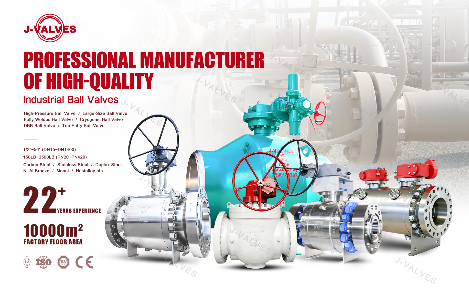
A fully welded trunnion mounted ball valve is a quarter turn isolation valve whose body sections are joined by a permanent circumferential weld rather than a bolted flange, with the ball carried on top and bottom trunnion bearings instead of floating into the seat. The welded body removes the body gasket, the body bolts and the two flange faces, which together account for most external leakage paths on a conventional bolted trunnion valve.
J-VALVES manufactures this valve from 2 inch (DN50) to 56 inch (DN1400) in ASME Class 150 through Class 2500, with full bore or reduced bore and with butt weld, flanged or hub ends. The design basis is API 6D / ISO 14313, wall thickness follows ASME B16.34, face to face dimensions follow ASME B16.10, and fire qualification is to API 607 / ISO 10497.
Because there is no body joint to open, the valve is normally specified where it will be buried, wrapped or left unattended for long periods: gas transmission block valve stations, city gate stations, district heating mains, underground storage wells and FPSO cargo or seawater lines. The trade off is explicit. You give up in line access to the ball and seats in exchange for a body with no gasketed joint to re torque, no bolts to corrode and a service life quoted in decades rather than in maintenance intervals.

Fully Welded or Bolted Body: How to Choose
The decision is usually made by installation method, not by pressure class. If the valve goes into a pit, a sleeve or directly into the ground, the welded body wins because there is nothing to inspect and nothing to leak. If the valve sits on a skid or in a plant where the body can be opened during a turnaround, a bolted body is easier to maintain and cheaper to buy.
Selection Factor | Fully Welded Body | Bolted Body |
|---|---|---|
Body joints | One circumferential weld, no gasket | Flange joint with spiral wound gasket and studs |
External leak paths | Body weld and stem seal only | Body weld, body gasket, body studs, stem seal |
Buried or sleeved installation | Preferred, no corrosion trap at the joint | Needs an accessible pit for inspection |
Body opening in service | Not possible, ball and seats are sealed for life | Possible at turnaround for seat replacement |
Stem seal renewal | Upper stem O rings replaceable in line | Replaceable in line |
Weight at equal bore | Lower, no body flanges or studs | Higher by the flange and bolt mass |
Relative cost | Higher first cost, lower lifetime cost | Lower first cost, higher maintenance cost |
Typical duty | Transmission pipeline, district heating, underground storage, subsea | Plant process, metering skid, manifold |
The rule most pipeline engineers apply is simple. If the valve will be inaccessible for more than five years, specify fully welded. If it will be opened at every turnaround, the welded body adds cost without adding value.
How the Welded Body Is Built
A fully welded body is not a bolted body with the flange welded shut. The body halves are machined as a matched pair, with the seat pockets, trunnion bores and end connections cut before welding so that seat concentricity is set by the machining rather than by the weld. The halves are then fitted, aligned and joined with a root pass that fully penetrates the wall, followed by fill and cap passes.
The weld sequence matters more than the weld itself. For carbon steel bodies in Class 900 and above the joint is preheated before the root pass and post weld heat treated after the cap pass to relieve residual stress in the heat affected zone. For stainless and duplex bodies the interpass temperature is capped instead, and the root is purged with argon to keep the wetted inner surface free of oxide for the life of the valve.
The critical constraint in a welded body valve is heat. The ball, seats and seals are already inside the body when the closure weld is made, so weld heat input has to be controlled to keep the seat inserts below their softening point. J-VALVES controls this with a chill ring around the weld prep, a monitored interpass temperature and a sequence that moves around the circumference in balanced steps instead of running one continuous pass. Seat pockets are checked dimensionally after welding, and the valve is not released to test until the body has cooled to ambient.
Every body weld is then examined. Root and cap receive penetrant testing, and the full volume is examined by radiography or ultrasonic testing depending on wall thickness and access. Weld maps, welder identification and heat numbers are recorded, so the weld on any individual valve can be traced back to the qualified procedure and the operator who made it.
Seat Design: SPE, DPE and DIB
Seat behaviour is the most important specification on a welded body valve, because a seat that fails cannot be reached by opening the body. J-VALVES offers three arrangements, and they are not interchangeable.
Seat Arrangement | Seals Both Directions | Cavity Self Relief | Double Barrier | Best Suited To |
|---|---|---|---|---|
Single piston effect (SPE) | Yes, line pressure assists one seat and relieves the other | Yes, thermal expansion vents to the low pressure side | No | Above ground lines, standard gas and water duty |
Double piston effect (DPE, DIB 1) | Yes, line pressure assists both seats | No, needs an external relief device | Yes | Buried and welded body valves, critical isolation |
Combination (DIB 2) | Yes, SPE one side and DPE the other | Yes, in the preferred flow direction | Yes, in the preferred direction | Lines where one side must self relieve |
For a welded body valve the recommendation is DPE, also called DIB 1. In that arrangement both seats are pushed onto the ball by line pressure from either side, so if one seat is damaged by debris the other still isolates the line. The cost is that the body cavity can no longer vent its own thermal expansion, so the cavity must be protected by an external relief valve or a bleed line to a safe location.
All three arrangements share the same spring preload. A set of helical springs sits between each seat ring and the body and pushes the seat onto the ball, so the valve seals even at zero line pressure, which is what allows a seat test to be run on an empty line. As pressure rises the piston area adds to the spring force, so sealing improves with pressure instead of depending on it.
Seat inserts are PTFE or RPTFE as standard, PEEK for higher temperature, and tungsten carbide, chrome carbide or ENP faced metal for abrasive duty. Every seat on 6 inch and larger valves, and on all welded body valves regardless of size, carries a sealant injection fitting so that sealant can be injected into the seat ring if the insert is scored by solids. Injection is a temporary measure that buys time to the next planned shutdown, not a repair.
Materials and Service Selection
Body material is driven by pressure class, bore and fluid. Forged A105 is the default for Class 900 and above and for sizes where the wall is thick enough that casting quality becomes difficult to guarantee. Cast WCB or LCC covers the larger low and mid pressure sizes where forging would be uneconomic. A182 F316 and F51 duplex are selected for chloride, sour and low temperature duty.
Component | Standard | Options | Selection Note |
|---|---|---|---|
Body | A105 forged | WCB or LCC cast, A182 F316, F51 duplex | Forged preferred for Class 900 and above and for buried duty |
Ball | A182 F316 with ENP | 410 stainless hard chrome, F51, weld overlay | Hard facing for abrasive or high cycle duty |
Stem | A182 F316 | 17 4PH, F51, ENP | Blow out proof, anti static path to body |
Seat ring | A105 or F316 | F51, overlay on sealing face | Sealant injection port on all welded bodies |
Seat insert | RPTFE | PTFE, PEEK, tungsten carbide, chrome carbide, ENP metal | Follows temperature and solids loading |
Stem seal | O ring plus graphite | PTFE lip seal, live loaded gland | Graphite provides the fire safe secondary seal |
Body weld | Matching consumable to ASME IX | Overlay for corrosive service | Qualified procedure, weld map recorded |
External coating | RAL 5015 sky blue | 3 layer PE, FBE, epoxy for burial | 3LPE for direct burial, DFT recorded |
For sour service the full wetted set is supplied to NACE MR0175 / ISO 15156 with hardness limits verified on each heat, and the results are written into the material certificate rather than left as a general statement of compliance. For low temperature duty down to minus 46 C the body and the weld procedure are impact tested at the design minimum. For cryogenic duty to minus 196 C the valve uses an extended bonnet with a metal seat.
Technical Specifications
The table gives the standard envelope. Values apply to the base configuration and move when the seat, end connection, stem extension or operator changes, so the order drawing governs.
Item | Value |
|---|---|
Size range | 2 inch (DN50) to 56 inch (DN1400) |
Pressure class | ASME Class 150, 300, 600, 900, 1500, 2500 |
Body style | One or two piece fully welded, no body flange |
Bore | Full bore or reduced bore to API 6D table 1, piggable on full bore |
Design standard | API 6D / ISO 14313, ASME B16.34 |
Face to face | ASME B16.10 and API 6D |
End connections | Butt weld to ASME B16.25, flanged RF or RTJ to ASME B16.5 and B16.47, hub, transition pup pieces |
Body material | A105 forged, WCB or LCC cast, A182 F316, F51 duplex |
Seat arrangement | SPE, DPE (DIB 1), combination (DIB 2) |
Seat insert | PTFE, RPTFE, PEEK, tungsten carbide, chrome carbide, ENP metal |
Temperature, standard | Minus 29 C to plus 200 C with soft seat |
Temperature, low | Minus 46 C with low temperature trim |
Temperature, cryogenic | Minus 196 C with extended bonnet and metal seat |
Operation | Gearbox, pneumatic, electric, gas over oil |
Shell test | API 598, 1.5 times rated pressure |
Seat test | API 598, 1.1 times rated pressure, both directions |
Fire safe | API 607, ISO 10497, API 6FA |
Fugitive emission | ISO 15848 1, class B or better on request |
Marking | API 6D nameplate with heat number and PSL level |
Buried Installation and Extended Stem
Most fully welded valves are bought for burial, and burial changes the stem design. The stem is extended from the ball to a gland plate at ground level, so the stem seal sits above the pit or above the ground line where it can be reached. The extension is a solid shaft inside a sealed tube, and a failure of the upper stem seal does not open a path from the buried body to atmosphere.
Three details decide whether a buried valve survives twenty years underground. The first is coating: a three layer polyethylene or fusion bonded epoxy system applied over the body and the weld area, with the field joint coated after the tie in weld and the dry film thickness recorded. The second is cathodic protection: a welded body has no isolated bolts or gaskets to shield current, so the whole body sits at one potential and the coating plus anode system can be designed as a single entity. The third is the cavity relief path, which on a DPE valve has to be piped to a vent above grade rather than left plugged.
Extended stem lengths are made to order and quoted against the depth of cover, the pit depth and the operator height, so the dimension comes from the site drawing rather than from a catalogue. Above ground installations use the standard stem with a gearbox or actuator mounted on an ISO 5211 pad.
Standards and Compliance
The valve is designed, welded and tested against the standards that govern pipeline isolation equipment. Two entries in the table deserve a note, because they are the ones most often misunderstood at enquiry stage.
Requirement | Standard | Availability |
|---|---|---|
Pipeline valve design | API 6D / ISO 14313 | Standard |
Pressure and wall thickness | ASME B16.34 | Standard |
Face to face and end to end | ASME B16.10 | Standard |
Weld end preparation | ASME B16.25 | Standard |
Flange ends | ASME B16.5, ASME B16.47 | Standard |
Pressure testing | API 598 | Standard |
Fire type testing | API 607, ISO 10497, API 6FA | Standard |
Welding qualification | ASME BPVC Section IX | Standard |
Non destructive testing | ASME Section V, ISO 9712 personnel | Standard |
Sour service | NACE MR0175 / ISO 15156 | Optional |
Fugitive emissions | ISO 15848 1 | Optional |
European pressure equipment | PED 2014/68/EU | Optional |
Material certificate | EN 10204 3.1 | Standard |
Product specification level | API 6D PSL 2, PSL 3 | Optional |
PSL 3 is not a material upgrade, it is a documentation and testing regime: it adds full heat number traceability, hardness verification on pressure retaining parts and NDT beyond the PSL 2 baseline. Pipeline operators whose own specification already calls for it should confirm the level at enquiry rather than after the order. ISO 15848 1 is a type test on the stem seal, and the class achieved depends on the packing arrangement, so a class B request should state the test temperature and the number of mechanical cycles.

Manufacturing, Welding and Traceability
Production of a welded body valve is a sequence of qualified steps rather than a single build. Body halves are forged or cast, rough machined, stress relieved where the procedure requires it, then finish machined so that seat pockets and trunnion bores are concentric to the bore within the drawing tolerance. The ball, seats, springs and stem are assembled into one half, the second half is fitted, and the closure weld is made under the controlled heat input described earlier.
Welding is performed to a procedure qualified under ASME Section IX, with a procedure qualification record on file for each material and wall thickness combination. Welders are qualified to the same code and each weld carries the welder stamp in the weld map. Consumables are controlled by batch and the batch number enters the record. After welding the body is radiographed or ultrasonically examined, then hydrostatically tested, then cleaned, coated and marked.
Traceability runs from the heat number on the body through the weld map, the NDT reports, the test report and the certificate. Every pressure retaining part carries a heat number that can be matched to an EN 10204 3.1 certificate, and the nameplate carries the API 6D marking, the class, the size, the heat number and the PSL level.

Testing and Inspection
Nine checks are recorded before the valve is released. Each one produces a document that enters the order file, so the buyer receives a package that can be audited against the valve on site years later.
Step | Check | Acceptance |
|---|---|---|
1 | Incoming material, chemistry and heat number | EN 10204 3.1, PSL 3 where specified |
2 | Machining, bore, seat pocket, face to face | Drawing and ASME B16.10 |
3 | Body weld, penetrant plus radiographic or ultrasonic | ASME Section V, no rejectable indication |
4 | Assembly and function, open and close torque | Smooth travel, no binding, torque recorded |
5 | Shell test at 1.5 times rated pressure | API 598, no leak at body or weld |
6 | Seat test at 1.1 times, both directions | API 598, ISO 5208 rate A where specified |
7 | Sealant injection and cavity relief function | Free passage, check valve holds |
8 | Coating dry film thickness and holiday test | Specified DFT, no holiday on buried valves |
9 | Final inspection, marking and document review | Nameplate and certificate set complete |
Seat testing on a welded body valve is run in both directions on both seats, which is more than a bolted body valve normally receives. The reason is that the seats cannot be reached later. Where the order calls for it, a witnessed test, a low temperature test or a nitrogen gas seat test can be added, and the witness name and date are recorded on the test report.
Applications
Transmission pipeline block valve stations are the largest single use. The valve is buried beside the line, the stem is extended to a gearbox or gas over oil actuator above grade, and the welded body means the only maintenance points are the stem seal and the operator.
City gate and metering stations use the valve upstream and downstream of the metering run, where double block and bleed seats let the run be isolated, vented and proved before a meter is changed. District heating mains use the welded body for a different reason: there is no gasket to weep over a twenty year life, and the lower thermal mass of the body reduces heat loss at the valve.
Underground gas storage and salt cavern wells specify the Class 1500 and 2500 versions, where the DPE seat and the sealant injection port give a second chance at sealing without pulling the valve. LNG and cryogenic duty uses the extended bonnet version so the stem seal stays above the cold zone, with a metal seat and a body tested at the design low temperature.
Offshore and FPSO installations use duplex and super duplex bodies for seawater and cargo duty, where the welded body removes bolted joints that would otherwise need inspection in a confined space.
Installation, Operation and Maintenance
At installation the weld ends are aligned within the root gap and fit up limits of the applicable piping code, usually ASME B31.4 or B31.8 for pipelines and B31.3 for plant piping. The valve is welded in the open position with the bore protected, the root is purged, and the field weld is inspected to the same standard as the body weld before the joint is coated. A valve welded closed traps heat and can distort the seat, so the open position is not optional.
Before burial the cavity relief line, the drain and the sealant injection points are proved clear and the coating holiday test is completed. After burial the stem is checked for free rotation through a full quarter turn, and the open and closed indicators are set against the operator.
In service the valve needs very little. Stem seal leakage is the one predictable wear item, and the upper O rings can be renewed in line by removing the gland plate with the valve closed and the cavity vented. Seat leakage, if it appears, is treated with sealant injection through the fitting on the seat ring, which restores sealing temporarily and should be followed by planning a replacement. Gearbox oil is changed at the interval in the operator manual, and the cavity relief device is checked for blockage at each station inspection.
How to Specify and Order
A complete enquiry needs twelve items, and a valve ordered without them usually comes back with a clarification. State the size in inch and DN, the pressure class, the bore (full or reduced), the body material, the ball and seat material, the seat arrangement (SPE, DPE or DIB 2), the end connection and its standard, the stem extension length if buried, the operator type, the design and test standards, any NACE or PSL requirement, and the coating system.
Standard configurations ship in two to four weeks from a single piece. The document package includes the EN 10204 3.1 material certificates, the weld map and NDT reports, the dimensional report, the shell and seat test report with torque record, the coating report and the packing list. Third party inspection can be arranged at any stage and the witnessed results are added to the package. Export packing uses a wooden case with the bore plugged and the weld ends protected by caps.
FAQ
Q: What is the difference between a fully welded and a bolted trunnion ball valve?
A: A fully welded valve joins its body halves with a circumferential weld and has no body gasket or body studs, so it has fewer external leak paths and can be buried permanently. A bolted valve has a flanged body joint that can be opened at a turnaround to replace the ball or seats. The welded body is chosen for inaccessible service, the bolted body for maintainable service.
Q: Can a fully welded ball valve be repaired if a seat leaks?
A: The body cannot be opened, so seat repair is limited to two options. Sealant injection through the fitting on the seat ring restores sealing temporarily and buys time to a planned shutdown. If that fails, the valve is cut out and replaced. This is why DPE seats, which keep a second barrier in place, are recommended on welded body valves.
Q: Why is double piston effect recommended for a welded body valve?
A: In a DPE or DIB 1 seat, line pressure pushes both seats onto the ball from either side, so a damaged seat on one side still leaves the other side sealing. Because the body cannot be opened for repair, that second barrier is worth more than the simpler cavity self relief of a single piston effect seat. The cavity then needs an external relief device.
Q: How long is the stem extension for a buried valve?
A: The length is made to order and measured from the valve centre line to the operator mounting face, based on the depth of cover, the pit or sleeve depth and the height of the gearbox or actuator. It is taken from the site drawing, not from a standard table, because the depth of cover varies by pipeline class and location.
Q: What sizes and pressure classes are available?
A: J-VALVES supplies the fully welded trunnion mounted ball valve from 2 inch (DN50) to 56 inch (DN1400) in ASME Class 150, 300, 600, 900, 1500 and 2500. Full bore and reduced bore are both available, and full bore valves are piggable to the API 6D bore table.
Q: Is the valve fire safe and suitable for sour gas?
A: Yes. Fire qualification is to API 607, ISO 10497 and API 6FA, with a graphite stem seal and a metal seat backup that hold a seal after the soft insert is destroyed. For sour gas the wetted parts are supplied to NACE MR0175 / ISO 15156 with hardness verified on each heat and recorded in the EN 10204 3.1 certificate.
Hot Products


News
Sanitary Clamp Ball Valves: 3-A, FDA And CIP Design Requirements
A sanitary clamp ball valve is not a polished standard valve. Cavity, seat wiping, Ra, drainability and 3-A paperwork decide whether it survives CIP.
Read More
Slurry Ball Valve Selection: Wear, Velocity, Seats And Materials
1. Slurries do not wear valves out; velocity doesA ball valve in clean water service can run for twenty years. The same valve in a 30 percent solids tailings line can be scrap in four months, and the difference is almost never the pressure class or the body material. Abrasive wear scales roughly wit
Read More
Fire-Safe Ball Valve Design: The Metal Backup Seat Behind API 607
How a fire-safe ball valve survives API 607: the metal backup seat, graphite packing and body joint that keep sealing after the soft parts burn.
Read More
Metal Seated Ball Valve: Clearance, Thermal Growth And Leakage Class
Metal-seated ball valves seal on hardfaced contact, not polymer: how clearance, differential growth and seat spring load set the leakage class.
Read More