CHINA J-VALVES Offers Various High-quality I ndustrial Ball Valves
J-VALVES, a distinguished professional ball valve manufacturer rooted in China, takes pride in its extensive product portfolio. Our offerings span a wide range, including trunnion-mounted ball valves, floating ball valves, high-temperature ball valves, high-pressure ball valves, metal-sealed ball valves, ultra-low temperature ball valves, DBB ball valves, Three-way And Four-way Ball Valve, and fully welded ball valves. Each product is a testament to our commitment to precision engineering and reliable performance. Meticulously crafted, they are designed to not only meet but exceed the most stringent industrial demands, ensuring stable operation even under extreme conditions. This enables us to provide our clients with high-value services and makes our valves widely sought-after in industries.
Product Category
Contact Us


-
J-VALVES-Q41F
-
J-VALVES
Overview of the J-VALVES reduced bore DBB flanged ball valve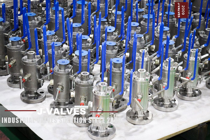
A double block and bleed valve carries one small port that reaches the space between its two isolating elements, and that port is where the whole idea is tested. The photograph on this page shows a three by two inch Class 600 stainless body with two levers and a needle valve on that port, and the question this page answers is what the port can and cannot tell you.
The valve is a two ball design. Each ball sits between two seat rings, and the space between the first ball and the second is a sealed volume of its own, bounded by the two closed balls and by the body bore. The bleed port is drilled into that volume and nowhere else. It does not reach the seat cavity around either ball, and no amount of turning the needle will make it.
The argument here is procedural. One port is enough to prove both balls, but only because the test is run twice, with the pressure applied to one side and then to the other. A test that opens the bleed once with pressure on one side has proved one ball and assumed the other, and that assumption is the one that fails when the line is opened for maintenance.
Design and Construction
The body is a forged stainless three piece pattern with two body joints, and it carries two balls on separate stems, each with its own seat pair. Two levers on top, one per stem. The needle valve on the centre port is the bleed, and the plug at the bottom of the body is a drain that belongs to a different volume, which is a distinction worth keeping straight before the test plan is written.
The reduced bore is what allows two balls to sit in a body of this length. A three inch body with a two inch bore has room for two balls of two inch nominal size and the seat stack around each of them, and the flange stays three inch so that the valve bolts to a three inch line. A full bore three inch twin ball body would be substantially longer, and the flange to bore relationship would put the seats further apart than the piping allows.
The seat arrangement decides what the bleed is for. With single piston effect seats the cavity pressure pushes the seat off the ball and relieves into the line, so the cavity empties itself in normal service and the bleed is a verification device. With double piston effect seats the pressure pushes the seat onto the ball from both directions, the cavity cannot relieve, and the bleed becomes the only way to empty it, which turns a convenience into a requirement.
Each body joint is a spigot and recess with a gasket, closed by a ring of studs, and on a body carrying two balls there are two joints, one at each end piece. The centre section is the piece that carries both balls and both sets of seat pockets, and it is the piece whose internal length decides whether the two balls close onto their seats at the same time.

Material Options
The body, the ends and both balls on this build are F316, with a polymer or metal seat and a stainless needle valve on the bleed. The parts that need a decision beyond the grade are the seats, the gaskets and the needle valve, and each of the three has a failure mode of its own.
| Part | Material on This Build | Note |
|---|---|---|
| Body and end pieces | A182 F316 forged | Three pieces, two joints |
| Balls | F316, polished | Two, one per stem |
| Stems | F316 or 17-4PH | One per ball, independent levers |
| Seats | Reinforced PTFE, polyimide, or metal | Sets the temperature and the relief behaviour |
| Seat effect | Single, double, or combined | Decides whether the cavity self relieves |
| Body joint gaskets | Spiral wound or metal jacketed | Two of them |
| Bleed valve | Stainless needle, graphited packing | The port the test is run through |
| Studs and nuts | B8M class 2 | Nickel alloy where the medium asks |
The seat effect row is the one to settle at the enquiry stage, because it changes the answer to a question most buyers ask much later: what happens to the cavity when the line heats up. A body full of liquid at ambient, closed off, and then heated will build pressure in that middle volume, and whether that pressure relieves into the line or stays in the cavity is decided entirely by the seat design.
The needle valve is not a detail on this valve. It is a small stainless valve with graphited packing, it is operated every time the cavity is proved, and it is the part most likely to be weeping when the valve is five years old. A bleed port fitted with a plug instead of a valve turns every proof into a job for a fitter with a wrench, and the proof stops being done.
Technical Specifications
| Item | Value |
|---|---|
| Size range | Two inch to four inch, DN 50 to DN 100 |
| Build shown | Three inch by two inch, Class 600 |
| Pressure class | Class 150 to Class 2500, PN 20 to PN 420 |
| Body | Forged A182 F316, three piece, two joints |
| Bore | Reduced, two inch through a three inch body |
| Balls | Two, on independent stems |
| Sealed volumes | Two seat cavities and one between the balls |
| Bleed | Needle valve into the middle volume only |
| Ends | Raised face or ring joint to ASME B16.5 |
| Face to face | Per drawing, B16.10 has no two ball entry |
| Design | API 6D, ASME B16.34, API 608 to Class 600 |
| Test | API 598 shell and seat, plus a cavity proof |
Class 600 on this size is inside the scope of API 608, which runs from DN 15 to DN 600 in Class 150 to Class 600, so the article can be built to either 608 or 6D. Above Class 600 the choice disappears, because 608 stops at 600 and 6D is the only document left. That is a real limit on a range table that offers this pattern to Class 2500, and it belongs in the specification rather than in a footnote.
The face to face line is the one that catches a replacement order. ASME B16.10 tabulates lengths for ball valves, and a body holding two balls with a cavity between them is not one of the tabulated articles. The dimension comes off the drawing, and a spool cut to the tabulated length for a single ball three inch Class 600 valve will not fit this article.
Standards and Compliance
| Requirement | Document | What It Means Here |
|---|---|---|
| Product requirements | API 6D | Design, materials, marking, and the DBB function |
| Alternative product standard | API 608 | Only to DN 600 and Class 600 |
| Wall and rating | ASME B16.34 | Class 600 for the group set by F316 |
| Flanges | ASME B16.5 | Facing and bolt circle |
| Pressure test | API 598 | Shell at 1.5 times, seat at 1.1 times |
| Fire test | API 607 or ISO 10497 | Type test against a stated scope |
| Material certificate | EN 10204 3.1 | Heat number per pressure part |
The double block and bleed function is a requirement in API 6D rather than a marketing term, and what the standard asks for is two independent isolating elements with a means of bleeding and proving the space between them. That is a structural requirement, and it is met here by two balls. A single ball with two seats is one isolating element, and calling it double block does not make the second seat independent of the first.
The fire test row applies to the bleed port as well, which is easy to overlook. A needle valve with polymer packing is a small pressurised fitting on the body, and in a fire the packing goes before the seats do. That is why the bleed valve on a fire rated build is specified with graphited packing rather than the standard polymer.
Manufacturing Process
Both balls and both seat pairs are machined as matched sets, and the centre section carries four seat pockets, two facing each way. The pockets on one side are cut from that face, the pockets on the other side from the other face, and the distance between the two sets is what sets the space the cavity occupies.
The bleed port is drilled after the seat pockets are finished, from the outside into the cavity, and its position relative to the pocket faces is checked because a port that breaks into a seat pocket rather than into the cavity is a port that will pass pressure from the wrong place. This is the kind of error that passes a hydrostatic test and fails a DBB proof, which is why the proof is worth running on every valve.
The two stems are machined to the same length and the two levers are keyed to them, so that both balls reach their seats on the same part of the quarter turn. A body where one ball seats early and the other seats late still seals, but the cavity proof becomes ambiguous: the bleed will be dry with one ball closed and the other open, and the operator cannot tell which is which from the outside.

Quality Control and Testing
| Step | Check | Acceptance |
|---|---|---|
| 1 Incoming | Heat number against the mill certificate | Chemistry and mechanicals |
| 2 Machining | Four seat pockets, cavity length | Drawing, both faces |
| 3 Port | Bleed breaks into the cavity, not a pocket | Drawing |
| 4 Shell test | Body and both joints at 1.5 times | API 598, no leakage |
| 5 Seat test | Four seat faces at 1.1 times | API 598 rate |
| 6 Cavity proof | Pressure one side, bleed watched, then reversed | Dry at the stated hold |
| 7 Operator | Both levers through a quarter turn, together | No fouling, seats contacted |
| 8 Final | Bleed closed, bores capped, tagged | Works standard |
The cavity proof row is the one that is unique to this article. With both balls closed the bleed is opened, pressure is applied to the upstream side, and the port is watched for the hold time in the test plan. Anything that appears there has passed the upstream ball, so the upstream ball is the element being proved. The valve is then turned round, or the pressure is applied from the other end, and the second ball is proved the same way.
The result is recorded per ball and per direction, which gives four results for a valve that has two balls. That is the same count as a single ball with two seats would produce, and the difference is what each result means: on this valve each result is a whole isolating element, and on the other it is one face of one element.

Applications and Industry Service
This valve belongs where a line has to be positively isolated and the isolation proved before the line is opened: instrument and impulse lines, sampling points, chemical injection, analyser systems and the isolation of pressure gauges and transmitters on a process unit. In all of those the reason for the valve is that a single block valve with a drain between it and the instrument is a two valve arrangement with a spool in the middle, and this replaces it with one body.
The reduced bore suits that duty because the flow is small. A two inch bore inside a three inch body passes everything an instrument line needs and keeps the body short enough to fit in a rack. On those lines the pressure drop across a reduced bore is not a cost, because there is no meaningful flow to lose.
It is the wrong valve where the line has to be pigged or where a full bore is needed for a scraper, because a two inch bore in a three inch line is an obstruction. It is also the wrong valve where nobody is going to run the proof, because an unproved double block and bleed is a single block valve with extra parts on it.

Installation, Operation and Maintenance
Installation is a flanged joint at each end with the usual rules: faces clean, pipe supported, studs tensioned in a cross pattern. The one addition on this valve is the orientation of the bleed. The needle valve has to be reachable from the platform and it has to be above the cavity, so that anything in the cavity can be bled out rather than sitting below the port, and that is decided by the flange bolt hole orientation.
The proof is run with the line isolated and the downstream side vented, in the sequence in the procedure, and the result is written down against the valve tag rather than remembered. A dry bleed is a statement about one ball at one moment, and the value of the record is in the comparison with the last one, not in the reading itself.
Maintenance is a seat replacement on each ball, done with the body joints broken and the balls lifted out. The bleed valve is repacked or replaced at the same interval rather than when it starts to weep, because a weeping needle valve makes every future proof ambiguous, and an ambiguous proof is the same as no proof when the line is opened.
How to Specify and Order
The six entries that define the article are size, class, body grade, seat, end connection and operator, and on this valve two more have to be added: the seat effect and the bleed arrangement. The seat effect decides whether the cavity self relieves; the bleed arrangement decides whether the cavity can be proved without a wrench. Both of them are cheap at the enquiry stage and expensive later.
The size has to be written as two numbers, the body size and the bore, because the two are not the same on this valve and the flange size follows the body. A three by two inch valve has a three inch flange and a two inch bore, and an order that says three inch without the second number can be supplied as a full bore three inch article which will not fit the space.
Documents to name: the EN 10204 3.1 certificate covering both end pieces and the centre section, the seat test record with four results, the cavity proof record showing the pressure side and the hold time for each of the two proofs, and the general arrangement drawing with the face to face dimension, the bleed position and the orientation of the needle valve relative to the flange bolt holes.
FAQ
Q: Does one bleed port really prove both balls?
A: It does, because the test is run twice. With both balls closed the bleed is opened and pressure is applied to one side; anything at the port has passed that ball, so that is the element being proved. The pressure is then applied from the other end and the second ball is proved the same way.
Q: What does the bleed not reach?
A: The annular space around each ball between its two seat rings. That space is sealed off by the ball and its own seats, and the port is drilled into the volume between the two balls and nowhere else. A test plan that treats the port as a general drain is testing the wrong volume.
Q: What changes if the seats are double piston effect?
A: The cavity stops relieving into the line. With single effect seats the cavity pressure pushes the seat off the ball and relieves; with double effect it pushes the seat onto the ball from both sides, so the cavity is sealed both ways and the bleed becomes the only way to empty it.
Q: Is this valve covered by API 608?
A: At Class 600 and three inch, yes, because 608 runs from DN 15 to DN 600 in Class 150 to Class 600. Above Class 600 the article is 6D only. The range table offers this pattern to Class 2500, and the top of that range is outside 608.
Q: Why is the bore smaller than the flange?
A: Because two balls and the cavity between them need axial space. A two inch bore inside a three inch body gives room for both balls and their seats and keeps the flange at the line size, where a full bore twin ball body would be substantially longer than the piping allows.



Hot Products


News
Remanufactured Ball Valves: Five Checks That Decide Whether A Rebuild Deserves A Certificate
A rebuild at 45 percent of price with half the life is no saving. Five checks that separate a real remanufacture from a repaint with a certificate.
Read More
The Squeeze Is A Residual: How Tolerance Stack-Up Decides Whether A Ball Valve Seals
No dimension sets the seat squeeze. Five tolerances do, in series. Why identical valves feel different, and why a new ball changes the arithmetic.
Read More
Why A Ball Valve Gets Harder To Turn: Five Causes, And The Test That Tells Them Apart
A ball valve that stiffens over months points at one of five parts. Measure torque with the line pressurised and again vented, and the split becomes visible.
Read More
The Ball Valve at Four Thousand Bar: Seat Load, Erosion And Fatigue in Waterjet Circuits
At 4,000 bar a 10 mm bore puts 31 kN on the seat and a 0.1 mm leak cuts steel. What a ball valve must survive in a waterjet or intensifier circuit.
Read More