A drawing is approved twice, and the second approval is the one you will need
The first approval is for the outline. Does this valve physically fit where it is going: the gap between the flanges, the height under the beam, the room for the lever to swing, the bolt pattern on the mating pipe. Almost every buying department does this one, and does it well, because it is the approval that answers the question the project asked.
The second approval is for the section. Is the thing inside the outline the thing that was ordered: this bore, this ball, this seat, this stem, this test. That approval is skipped far more often, and it is where the money is, because a valve can pass the first approval perfectly and fail the second completely. A ball valve GA drawing is the only document that lets a buyer do both before steel is cut, and a ball valve general arrangement drawing that carries an outline and no section has really only been approved once.
What follows is not a guide to drafting conventions. It is the short list of ball valve drawing dimensions and blocks that decide, at installation time, whether the valve was the right purchase, in the order they tend to bite.
One: face-to-face, the dimension that decides interchangeability
Face-to-face is the length between the two flange faces, and it is the dimension that decides whether a valve drops into an existing gap or whether the pipe has to be cut. It is also the dimension most often quoted as a bare number, which makes it impossible to check.
The ASME B16.10 face to face tables list these lengths by nominal size and by class, and they list more than one pattern for the same size, so the same valve can be legitimately built in more than one length. A drawing that carries a length but not the standard and the pattern it came from cannot be verified by anybody outside the supplier's own office. The correct entry on the drawing is a length plus a reference: this length, to B16.10, this pattern, for this size and class. With that on the sheet, a tape measure settles it in ten seconds. Without it, a disagreement about a hundred millimetres becomes a conversation about who read the catalogue correctly.
The same logic explains why replacement is harder than new build. A valve ordered today goes into a gap that was set by a valve ordered years ago, possibly to a different pattern, possibly with weld ends whose length is governed by a different table in the same standard. That is a long enough subject to have its own treatment in why replacement ball valves do not fit, and it is the single best argument for putting the number on the drawing with its reference attached.
Two: the bore, which the outline leaves out
A size is not a bore. DN50, or 2 inch, describes the end connections; it says nothing at all about the hole through the ball, and the hole is what the process sees. A full-port valve has a bore close to the pipe bore, though not identical to it, because the ball needs material around the seat. A reduced-port valve has a bore deliberately smaller than the pipe, and the amount by which it is smaller is a design choice made for torque reasons rather than a fixed percentage of anything.
So the drawing must state a ball valve bore diameter, and the parts list must say which ball is fitted. If the general arrangement shows only the end size, what has been approved is a size, not a valve. The failure this prevents is quiet and expensive: the valve bolts in, the line runs, and the flow is short of what the pump curve assumed, or the pig that was supposed to pass does not, or the pressure drop is higher than the calculation. None of those failures look like a purchasing error at the time, and all of them are one.
Three: a flange is four dimensions wearing one label
The order says DN50, Class 150. That is one label and four dimensions: outside diameter, bolt circle, number and diameter of bolt holes, and the facing. The drawing has to carry all four, and it has to name the standard they come from, because two valves that both read DN50 PN16 can be built to different drilling standards and will not bolt to the same pipe.
The ASME B16.5 flange dimensions, EN 1092-1 and JIS B2220 are three separate answers to the same nominal size, and the bolt circles and bolt counts differ between them. That is why the flange block on a GA drawing should read as a specification rather than a size: standard, size, class or PN, facing, and, where the facing is a ring joint, the groove. The facing itself is not a detail either. Raised face, flat face and ring joint are three different gasket interfaces, and a valve drawn with the wrong one is a valve that will be forced together with the wrong gasket. The wider question of how the end is chosen at all is covered in flanged, weld and threaded end connections; the drawing's job is only to pin down the answer that was chosen.
Four: height, swing and the ball valve actuator envelope
The dimension nobody checks until the skid is built is the one above the valve. Three numbers belong on the drawing: the height from the pipe centre line to the top of the stem or operator, the space the operator needs to move, and the space a person needs to reach it.
A lever sweeps through ninety degrees, so what it needs is not its length but its length plus a hand, in the plane it sweeps. A gear operator needs room for a handwheel and for somebody standing at it. An actuator is the worst case, because a cylinder with its accessories is longer, wider and heavier than the valve it is mounted on, and its air ports have a side. On an insulated line the insulation adds a layer to all of it, and on a skid the structural steel is usually exactly where the lever wants to go. This is why a ball valve actuator envelope belongs on the drawing as a swept shape and not as a note, and why the torque chain that sizes the actuator and the envelope that houses it have to be settled in the same conversation.
The ISO 5211 mounting pad is part of this block. Its designation says what will bolt on, and if the pad was not part of the order it cannot be added later without changing the stem and the bonnet. A drawing that shows a bare stem where the order asked for a pad has not drawn the valve that was bought.
Five: weight and lifting points belong on the drawing
Weight is the dimension that never appears in a technical argument and always appears in a rigging plan. It belongs on the drawing for the same reason the bore does: so that the number the site works to is a document rather than an estimate carried in somebody's memory from a similar job.
The same block should carry the lifting arrangement for the sizes where a valve is no longer a two-person object, and it should say whether the lifting points are on the valve body, the packing, or neither. A valve lifted from its lever, or from a flange bolt hole with a sling through the bore, is a valve that will be inspected for a bent stem three weeks later, and the inspection will find what the sling did.
The materials block: a grade without a process is not a material
The ball valve parts list material call-outs are the least read and the most consequential part of the drawing. Body, ball, stem, seat, seals, and for each one a designation that a certificate can be written against.
A standard designation carries a process with it, and that is the point. A216 WCB is a cast carbon steel; A105 is a forged carbon steel; A351 CF8M is a cast stainless; A182 F316 is a forged stainless. A parts list that says stainless steel, or 316, has not chosen a material, it has chosen a family, and the certificate that arrives at the end will be for whichever member of the family the works happened to use. The difference between the cast designation and the forged one is not academic, because it decides which specification the test certificate is issued to and which defects are possible in the part. This is the same distinction that decides which grade to order in the first place, set out in 304, 316 and 316L and what actually decides; the drawing's job is to make sure that decision survives into manufacturing.
The test block belongs beside it: the standard the valve is tested to, the medium, and the multiples for shell and seat, so that the acceptance criteria at the end of the order are the ones on the drawing and not the ones in somebody's recollection.
The revision letter has to travel with the valve
A drawing approved as revision A and manufactured as revision B is a claim waiting for a date. The revision letter is the only cheap way to prevent it, and it works only if it appears in four places: on the drawing, on the approval record, on the nameplate or tag fixed to the valve, and on the packing list. When something is questioned two years after delivery, the letter is the only thing that says which drawing the valve was built to, and without it the answer is a search through correspondence.
The block also needs a rule: any change to a dimension, a material or a test returns the drawing for approval. A revision that is issued for information and never approved is a change that has happened without a decision, which is the worst of both.
What each block must contain, and what breaks without it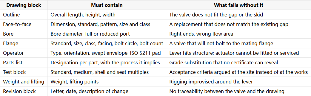
Five lines for the approval comment
An approval that says approved, no comment has approved the outline and nothing else. Five lines do the rest, and they cost a minute:
Bore stated. Face-to-face to ASME B16.10 with the pattern named. Flange drilling standard and facing named. Operator and its swept envelope shown, with the mounting pad designation. Parts list to standard designations, revision letter to appear on the nameplate and the packing list.
None of those five ask the supplier to change anything a competent works was not already going to do. They only make sure that what was done is written down, which is the entire function of a ball valve drawing approval.
How J-VALVES issues drawings
J-VALVES issues a GA drawing for approval before manufacture on ball valves from 1/2 to 56 inch (DN15 to DN1400), ASME Class 150 to 2500, in carbon steel, stainless steel, duplex and low-temperature grades. The drawing carries the outline and the section, the face-to-face reference, the bore, the flange specification, the operator envelope with its ISO 5211 pad where one is ordered, the parts list with standard designations, the test block, and a revision letter that is repeated on the nameplate and the packing list. Shell tests at 1.5 times and seat tests at 1.1 times the rated pressure, with EN 10204 3.1 certificates for body and stem on request.
Frequently Asked Questions
What must a ball valve GA drawing show? Two views and five numbers. The outline for fit and the section for content; then face-to-face with its standard and pattern, the bore, the flange specification, the operator envelope, and the weight. Add the parts list with standard designations and the test block, and the drawing covers everything that can become a claim later.
Does a GA drawing show the bore? It should, and often does not. The end size on the drawing belongs to the flanges, not to the ball, so a section without a bore dimension leaves the buyer unable to tell a full-port valve from a reduced-port one. If the bore is not on the sheet, ask for it, because it cannot be added to the valve afterwards.
Why do two DN50 PN16 ball valves have different bolt circles? Because PN16 names a rating, not a drilling standard. ASME B16.5, EN 1092-1 and JIS B2220 each define their own bolt circle, bolt count and facing for the same nominal size, so the drilling standard has to be named on the drawing and on the order. A valve built to one will not bolt to a flange built to another without an adapter.
Should the drawing be approved before production starts? Yes. Once the body is cast or forged and the bore is machined, every dimension on the sheet has become expensive to change. The approval is worth most in the window before material is released, and it is worth almost nothing after the pressure test.
What is the difference between the outline and the section on a valve drawing? The outline answers whether the valve fits: length, height, flange pattern, operator space. The section answers what the valve is: bore, ball, seat, stem, wall and the joints between them. A buyer who approves only the outline has confirmed that the valve will go in, not that it is the valve that was ordered.