


One word, four jobs
“With bypass” in a valve inquiry can mean four different things, and they are not variations of one idea. It can mean equalize the pressure before opening, so the valve can be operated without damaging its seat. It can mean keep the line running while the main valve is worked on. It can mean provide a warm-up or cool-down path so a cold line does not arrive at a closed valve all at once. And it can mean provide a relief path for trapped liquid that expands. Tap point, valve type, size and normal position are different for each of those, and the phrase on its own does not choose between them.
The consequence is not usually a wrong valve. It is a correct valve applied to the wrong job, which is worse, because everything looks right: the bypass line exists, it is on the drawing, it was built, and it does not do what the operating procedure assumes it does.
Why a large ball valve will not open against full differential
A quarter turn is a small motion, not a small force. When a ball valve is closed, the ball is held against the upstream seat by the differential across it, and the seat is pressed onto the ball by the same pressure. To rotate the ball you must first break that contact, and breaking it means sliding the seat face across the ball surface while the full load is still sitting on it.
That load is what a gear operator or an actuator is sized against, and it is the reason a large trunnion valve needs a gearbox at all; the chain from breakaway to running to seating torque is set out in actuator sizing and the torque chain. But the damage is not done by the load alone. It is done by the load multiplied by the distance the seat is dragged, and a seat dragged across a ball at full differential for a few degrees of travel has been lapped by the ball with whatever debris was in the gap.
This is the argument for equalizing, and it is a wear argument before it is a torque argument. The torque figure tells you whether the operator can turn the valve. The wear tells you whether he should turn it in that state, and the two answers can disagree: an actuator with generous margin will turn a valve that should never have been turned dry.
Equalization changes the pressure state, not the force
With the same pressure on both sides, the differential that pressed the seat onto the ball is gone. The seat is then held by its own spring preload, which is deliberately small, because that preload only has to seal at low pressure; the higher the pressure, the more the medium itself does the sealing. Turning the ball in that state is a different mechanical event. The seat lifts off, the ball turns without scrubbing, and the seat reseats on the other side when pressure returns.
That reframing has a practical consequence. If the purpose of the bypass is to protect the seat, the procedure has to equalize before the quarter turn begins, not during it. A bypass cracked open while the main valve is being turned still leaves a differential across the seat for part of the travel, and the scrubbing happens anyway, only more slowly. A half equalized valve has half the seat load and the same wipe.
It also explains why the equalization has to be complete rather than approximate, and why it takes time. The only state that removes the wear is equal pressure on both sides, and reaching it means moving enough mass through a small passage against a large volume. The bypass exists to make that possible inside the time the procedure allows; how the seat load itself behaves under pressure is described in seat loading on a floating ball valve, and the same logic applies to the upstream seat of a trunnion valve.
Where the bypass taps in, and the three mistakes
The upstream tap belongs upstream of the upstream seat, on the pressure side of the closed valve, not in the body cavity. A tap into the cavity is the most common mistake, because the cavity already has a port and it is the easiest place to weld a connection. It reads the wrong space. In a double block and bleed arrangement the cavity is precisely the volume between the two blocks, so a bypass taken from it equalizes the cavity with one side of the line and leaves the valve itself exactly as loaded as before.
The downstream tap belongs beyond the downstream seat, for the same reason in reverse. On a valve with a self-relieving seat the cavity is connected to the upstream side through the seat itself, so a cavity tap on that valve appears to work when the line is pressurized from one end and does nothing when the flow reverses. A bypass that works in one direction only is a bypass that fails on the day the line is turned around.
The third mistake is the tap that exists on the drawing and is plugged in the plant. A bypass valve that cannot be reached, a connection buried under insulation, a bypass line blanked during construction because it wept: each of those is a bypass in the documentation and not in the plant. The procedure that assumes it is a procedure with a step nobody can perform, and the person who discovers this is the operator at three in the morning.
A bypass left open is a leak across the isolation boundary
The bypass is a permanent connection between the two sides of a valve whose entire purpose is to separate them. Its normal position is therefore a safety decision, not an operating preference. Closed, it is a bypass. Open, it is a leak path that no isolation certificate will show, because the certificate is about the main valve and the main valve is doing exactly what it was asked.
That is where the three valve arrangement comes from: an isolation valve at each end of the bypass line, with the bypass valve between them. The two outer valves let the bypass valve be proved tight, and let it be replaced without cutting into a live line. A single bypass valve with no isolation is the arrangement built to save two valves. It cannot be tested for tightness without stopping the line, it cannot be replaced at all, and when its seat passes, the isolation test on the main valve fails and the main valve is blamed.
The position also has to be lockable, and the lock has to belong to the isolation procedure rather than to whoever added a padlock afterwards. A bypass that any passer-by can open is an isolation that depends on nobody being curious, which is not an isolation at all. Where the bypass is a warm-up path it may be required to be open, and then the requirement has to be written down as such, with the reason, so that the next shift does not close it “for safety”.
The bypass valve wears like a throttling valve
During equalization the small valve in the bypass is the restriction, and it is being used to control flow, which is not what a general purpose ball valve is for. At crack-open the passage is smallest, the velocity is highest, and whatever solid or flashing liquid is in the line does its damage there. The seat edge erodes, the ball scores, and the damage concentrates in the first few degrees of travel, which is exactly the position the valve is used in every single time.
If the procedure needs flow control rather than a path, the ball valve is the wrong component even when it is the right size. A needle or globe valve, or a V-port ball valve with a characterised disc, divides the pressure drop over more travel and puts the wear on a part designed to take it. Where the medium can flash or freeze, the same argument applies with more force, because the restriction is also the place where the temperature collapses.
The bypass valve also inherits the duty cycle of the procedure, and duty cycles are rarely written down. A valve opened twice a year is a valve whose seat never beds in; a valve opened twice a shift will need a seat long before the main valve does. Buying a trunnion valve selected for the main duty and putting a stock ball valve in the bypass is a way of concentrating the whole maintenance burden of the installation into the smaller, cheaper component.
Sizing is a procedure question, not a ratio question
Bypass sizes are habitually chosen by rule of thumb: one size down, two sizes down, the same as the drain. The number that actually sets the size is the time the procedure allows for equalization, together with the volume that has to be filled or vented. Both of those live in the operating procedure, and neither of them appears on a valve data sheet.
That is why a bypass should be quoted against a stated equalization time rather than against a pipe size. A supplier told “equalize within the time the procedure allows, downstream volume is this” can size it and state the assumption behind the size. A supplier told “with a one inch bypass” has been handed the answer instead of the question, and will build it.
The same logic covers the cases where equalization is not possible at all: a line whose two sides must never be connected, or a medium that must not be allowed across. Those need a different answer, such as a pressure balanced seat, an actuator with enough margin for the dry operation, or explicit acceptance of seat wear at a defined interval. They are engineering decisions, and a bypass is not a substitute for one.
Bypass, bleed and cavity relief are three different paths
A bypass changes the pressure state on the downstream side by connecting it to the upstream side. A bleed proves that a cavity is at zero by letting it out. A cavity relief protects the body when trapped liquid expands. Three different functions, drawn with symbols from the same family, and described with the same word in most site conversations.
Using a bleed as a bypass is the commonest confusion, and it fails for a simple reason: a bleed port is sized to pass a diagnostic trickle, not to fill a downstream volume inside the time a procedure allows. The operator opens it, waits, the gauge does not move, and the conclusion is that the valve is stuck when the valve is fine and the port is simply too small.
Using a bypass as a relief is the other direction and the more dangerous one, because a bypass line is not necessarily rated or routed for the relief case. A relief path has to discharge at the rate the thermal expansion produces, into something that can take the discharge. A one inch bypass into a bucket is not a relief path, and the fact that it is connected does not make it one.
When the bypass is temporary, the procedure is the product
A temporary bypass assembled on site, out of hoses, a portable valve and clamps, is a pressure boundary that nobody designed. The rating of the hose, the restraint at each end, the direction the open end faces, the order of the valve lineup and the signature that releases it are all part of the equipment, and none of them arrives in the box.
The rules are unglamorous. The temporary line is rated for the higher of the two sides, never the average. It is restrained so that the reaction at the connection does not become a bending load on the flange. It is depressurized before it is broken, not merely isolated. And it is removed before the line returns to service, with the removal recorded, because a temporary bypass left in place is a permanent bypass that no one specified and no one tests.
Where the bypass is drawn as a dotted line on a P&ID, it will be built by whoever reads the drawing, to whatever size is on the truck. The dotted line is a note to the future, and notes to the future are how unrated bypasses get installed. On valves that are opened for maintenance rather than for operation, the same decision shows up as a choice between top entry and side entry construction, since a valve that can be worked on in line needs less bypass than one that has to be cut out.
What to put in the order
Eight lines settle it, and each one closes a specific failure.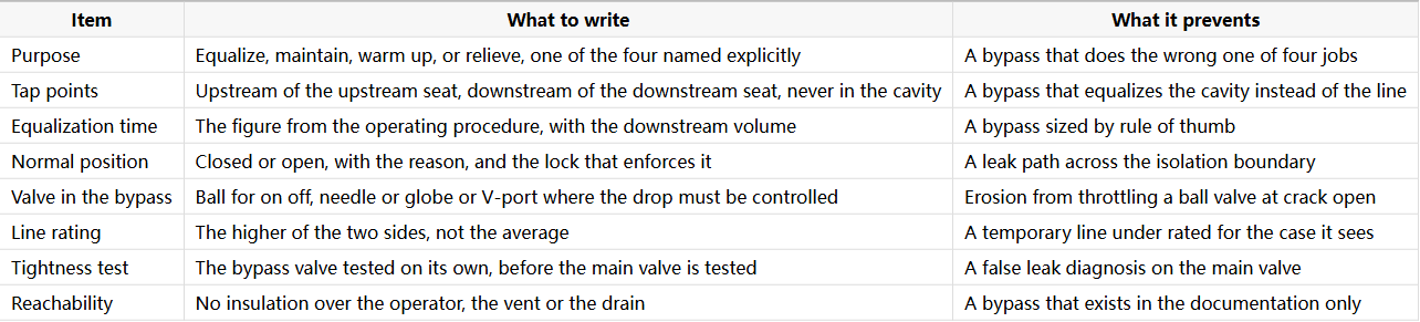
Where J-VALVES sits
J-VALVES builds both valves in the arrangement: the main trunnion mounted ball valve and the smaller ball valve in the bypass, from 1/2 to 56 inch (DN15 to DN1400) in ASME Class 150 to 2500, shell tested at 1.5 times and seat tested at 1.1 times rated pressure to API 598, with EN 10204 3.1 certificates available.
What we do not do is design the bypass loop. The tap points, the equalization time and the normal position belong to the piping design and the operating procedure, and they are the three inputs that decide which valve goes in the bypass. When they are stated, both valves can be quoted against them. When they are not, the honest deliverable is a question rather than a proposal, because a bypass built around an unstated procedure is a fitting that will be blamed for a decision nobody made.
Frequently Asked Questions
Does a large ball valve need a bypass to open? It does not need one to be turned; it needs one if the seat is to survive being turned. The differential holds the seat against the ball, so opening under full load drags the seat across the ball surface. Equalizing first removes that load and lets the ball turn without scrubbing. A valve with a large actuator will open without a bypass, which is exactly why the wear is easy to miss until the seat is inspected.
How big should a ball valve bypass be? The size is set by the equalization time the operating procedure allows and by the volume that has to be filled or vented, not by the size of the main valve. There is no universal ratio, and a rule of thumb such as one size down is a guess that happens to work on some lines. State the time and the volume, and let the size be calculated against them.
Can the cavity bleed be used as a bypass? No. A bleed port is sized to pass a diagnostic trickle so that a cavity can be proved at zero, while a bypass has to move enough mass to bring a downstream volume to line pressure inside the time allowed. Opening a bleed and waiting produces a gauge that does not move, and the usual conclusion is that the main valve is stuck when the port is simply too small for the job.
Does a bypass reduce the torque needed to operate the valve? It does, as a side effect, because the seat load that produces most of the breakaway torque comes from the differential. But treating that as the purpose is a mistake. Actuator sizing still has to assume the valve can be operated without a bypass, since a bypass may be closed, plugged or forgotten, and the reason to equalize is seat wear rather than torque.


