CHINA J-VALVES Offers Various High-quality I ndustrial Ball Valves
J-VALVES, a distinguished professional ball valve manufacturer rooted in China, takes pride in its extensive product portfolio. Our offerings span a wide range, including trunnion-mounted ball valves, floating ball valves, high-temperature ball valves, high-pressure ball valves, metal-sealed ball valves, ultra-low temperature ball valves, DBB ball valves, Three-way And Four-way Ball Valve, and fully welded ball valves. Each product is a testament to our commitment to precision engineering and reliable performance. Meticulously crafted, they are designed to not only meet but exceed the most stringent industrial demands, ensuring stable operation even under extreme conditions. This enables us to provide our clients with high-value services and makes our valves widely sought-after in industries.
Product Category
Contact Us


-
J-VALVES-Q11F
-
MSNL
Overview of the J-VALVES pneumatic three piece screwed NPT ball valve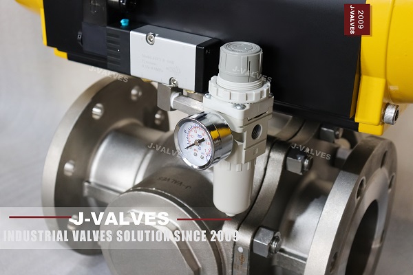
Two pneumatic actuators sit on a desk and look identical: same body, same ports, same square drive. One of them will close the valve when the air is lost and the other will leave the ball exactly where it was. The difference is a spring inside the housing, and it is the first question that should be asked about an automated valve, ahead of torque, ahead of bore and ahead of price.
The valve underneath is a three piece 316 stainless body with NPT threaded ends, a floating ball on polymer seats, offered from a quarter inch to four inch, with a maker rating of 1000 PSI on the page. The actuator is mounted on a bracket over an ISO 5211 pad, and the bracket and coupler are as much a part of the assembly as the body.
The argument here is that fail position is a property of the actuator and not of the valve, that a double acting unit has no fail position at all, and that the pressure figure on the page belongs to a different language from the standard it is printed beside. All three points change what should be written on an order.
Design and Construction
The body is three pieces: two end pieces carrying the threads and one centre section carrying both seat pockets. The ball and the two seats load into the centre section, and the end pieces close onto it with gaskets and studs. That is two gasketed joints rather than the one a two piece body has, and both are pressure boundaries that are tested as such.
The three piece pattern exists for the machine before it exists for the fitter. The two seat pockets are cut from opposite faces of the centre section in one setting, so the two seats are concentric with each other by construction rather than by a second operation. Each end piece can be machined and inspected on its own, and the threads are cut on a piece that does not yet carry the bore. Access for maintenance is real, but it is what falls out of that arrangement rather than the reason for it.
The actuator is a quarter turn pneumatic unit with a pinion and two pistons, or with one piston and a spring stack. In the double acting version air on one port drives the pistons one way and air on the other port drives them back. In the spring return version one side holds a spring pack and air on the single working port drives against it, so removing the air lets the spring drive the stem back.
The junction between valve and actuator is the pad, the bracket and the coupler, and it is the part most often got wrong. The pad is drilled to ISO 5211 with a stated bolt circle and a stated drive form, the bracket converts that to the actuator's own pattern, and the coupler has to match the stem flats. A bracket that lines up but a coupler that is loose will round the stem flats within a few hundred cycles.
Material Options
The page gives 316 for the body, the ball and the stem, and adds nothing for the actuator, which is where the material choice for the assembly actually continues. The table keeps the page's entries and adds the parts that have to be selected rather than assumed.
| Part | Material on This Build | Note |
|---|---|---|
| Body and end pieces | 316 stainless, three pieces | Two gasketed joints |
| Ball | 316 stainless, polished | Floating, no trunnion |
| Stem | 316 stainless | Blowout proof shoulder |
| Seats | PTFE or reinforced PTFE | Sets the temperature ceiling |
| Body joint gaskets | Spiral wound or PTFE sheet | Two of them |
| Studs and nuts | A4 stainless | Sized by the class |
| Actuator body | Anodised aluminium | Seals to the maker's specification |
| Coupler and bracket | Stainless or plated steel | Matched to the stem flats |
The two joints are the material decision that differs from a two piece body, because each joint is a gasket and a ring of studs that has to hold the class. Two joints mean two gaskets and twice the stud torque work, and they also mean two places where a seal can fail invisibly behind insulation. On the other hand, the centre section can be replaced without cutting the line out, which is the practical return on the extra joint.
The actuator materials are usually outside the buyer's control, but the seals inside it are not. Nitrile seals are the default and they are fine for clean dry air; where the air is oily or where the ambient is cold, the seal compound has to be chosen, and an actuator that sticks at minus ten is a seal problem rather than a valve problem. The air supply itself should be filtered and dry, because a spool valve fed with wet air will fail long before the ball does.
Technical Specifications
The specification below keeps the page's figures and separates the pressure language, which is the part that most needs separating.
| Item | Value |
|---|---|
| Size range | Quarter inch to four inch, DN 6 to DN 100 |
| Pressure rating | 1000 PSI on the page, a maker rating |
| For comparison | Class 600 is 102.1 bar at 38 Celsius |
| Body | 316 stainless, three pieces, two joints |
| Ball | 316 stainless, floating |
| Seats | PTFE or reinforced PTFE |
| Temperature | Minus 29 to plus 200 Celsius on a polymer seat |
| Ends | NPT to ASME B1.20.1 |
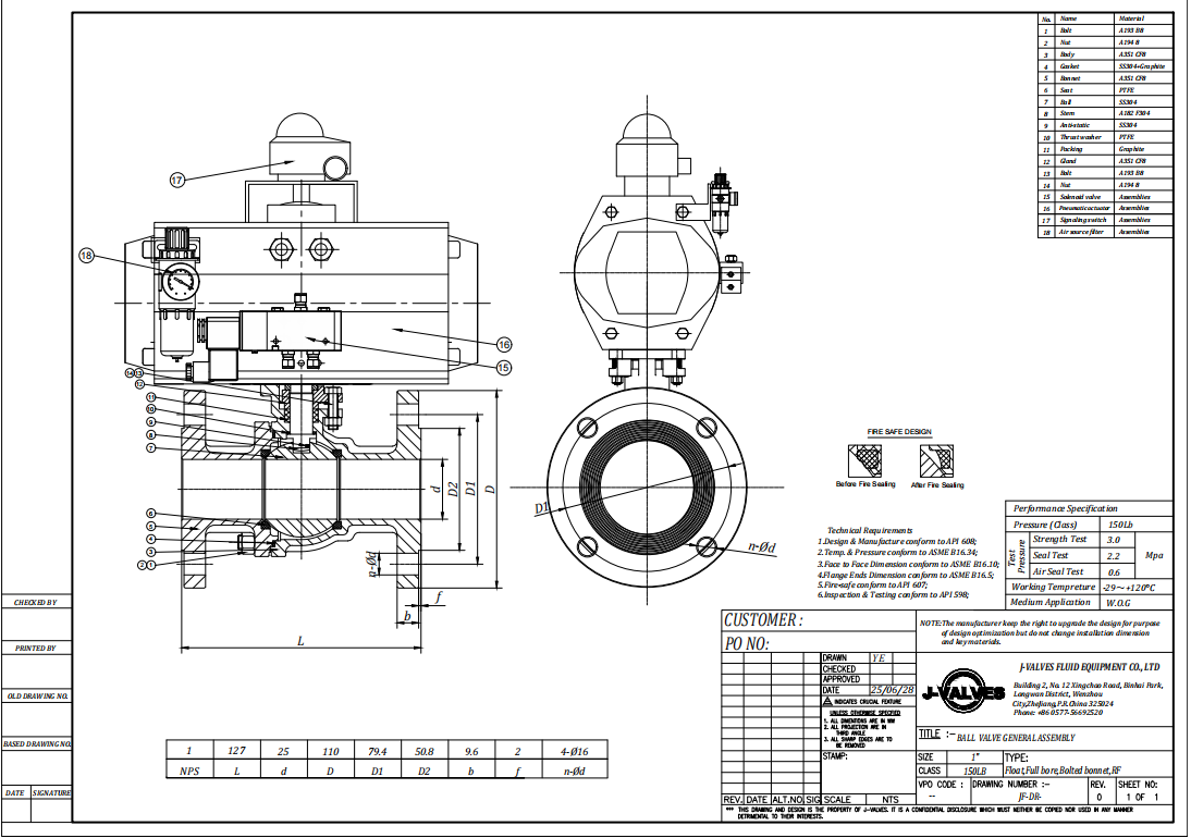
| Design | API 608, ASME B16.34 |
| Test | API 598 and ISO 5208 |
| Actuator | Double acting or spring return |
| Interface | ISO 5211 pad, bracket, coupler |
The pressure line is the one that has to be read carefully. API 608, which the page cites, works in classes: 150, 300 and 600. There is no 1000 psi class in it. Class 600 for a 316 body is 102.1 bar at 38 Celsius according to the material group table, and that is a pressure with a temperature attached to it. A figure of 1000 psi with no temperature attached is a commercial rating for cold non shock service, and it sits beside the standard rather than inside it.
The NPT thread is the second thing that carries no rating. ASME B1.20.1 defines the thread form, the taper and the gauging, and it says nothing about how much pressure a threaded joint will hold. The pressure boundary at a threaded end is made by the thread engagement and the sealant, and the body behind it is rated by its class. A valve that is described as 1000 psi at the threads is describing the body and hoping the joint follows.
Standards and Compliance
Five documents appear across the page's standard lines, and one of them is used outside its scope. The table sets out what each fixes and where it stops.
| Document | What it fixes | What it does not fix |
|---|---|---|
| API 608 | Steel ball valves, Class 150 to Class 600 | A 1000 psi rating of any kind |
| ASME B16.34 | Wall thickness and material groups | Thread form or joint strength |
| ASME B1.20.1 | NPT thread form, taper and gauging | Pressure rating of the joint |
| API 598 | Shell and seat test procedure | Actuator behaviour or cycle life |
| ISO 5208 | Leakage rate classes for industrial valves | Which rate the order requires |
ISO 5208 is the one worth pausing on, because it is a rate table rather than a pass mark. It defines leakage classes from a bubble rate downward, and a valve tested to ISO 5208 without a stated class has been tested to a procedure with no acceptance criterion. On a soft seated ball valve the usual expectation is the tightest class, and that expectation should be written as a class rather than as a word.
The fire test under API 607 is a type test rather than a routine one: it says that a valve of this design and size was tested once, not that the unit in the crate was. That distinction matters when a project asks for a fire safe certificate and receives a test report for a different size, which happens more often than it should.
Manufacturing Process
The centre section is the piece that carries the design. Both seat pockets are bored from their respective faces with the piece held once, so the two pockets share an axis; then the bore is cut through, and the result is a body whose two seats are concentric without a second setting. That single operation is what a three piece pattern buys, and it is why the pattern survives in a market that would otherwise prefer two pieces.
The end pieces are machined separately, threaded, and then faced so that the thread axis is square to the gasket face. A thread that is square to nothing will pull the joint into a bind when it is tightened onto a pipe, and the leak that follows is blamed on the gasket. The threads themselves are gauged with a plug or ring gauge to B1.20.1 rather than checked by eye.
Assembly fits the seats and the ball into the centre section, closes both end pieces onto gaskets, fits the stem and packing, then mounts the bracket and the actuator and cycles the assembly. The cycle test is done with the actuator fitted, because the bracket and coupler are part of the torque path and a misaligned bracket shows up as a stiff or incomplete stroke.

Quality Control and Testing
The shell test is applied with the ball open at one and a half times the class rating, and on a three piece body both joints are under observation. The seat test follows at one point one times, one side at a time, because a floating ball only loads its downstream seat. Both results belong on the record, and a single sided seat test should be read as half a test.
The actuator is cycled through its full stroke before dispatch, with the air supply at the maker's stated pressure, and the stroke is checked at the indicator or at the switch box if one is fitted. A valve that strokes on the bench but not on site is usually a bracket that has moved, and a bracket that is checked at the works with a torque wrench is one that will not move.
The plate and the actuator label are checked against the order together, because the assembly is sold as one item. Size, class, body grade, seat material and heat number belong on the plate; actuator model, spring direction and working pressure belong on the label. An assembly whose label says double acting and whose drawing says spring return will fail at commissioning, and the failure will look like a control problem.

Applications and Industry Service
The duty this assembly is sold for is small bore automated isolation on skids, dosing lines, sample systems, utility headers and packaged plant. A quarter inch to four inch line that has to open and close on a signal is exactly the case where a three piece screwed valve with a quarter turn actuator is cheaper than any alternative and easier to replace.
The spring return version is the one specified wherever the safe state has to happen without power. Fuel gas lines, chemical dosing, and any line where a loss of instrument air must not leave a valve open will carry a spring return unit, and the spring direction is written on the data sheet as fail closed or fail open. The double acting version is used where the valve can stay where it is, which is most process lines that are not safety related.
Where the assembly should not be used is on lines that need throttling, and on services where the medium would attack the actuator's seals or its anodised body. A ball valve is a quarter turn isolator; a pneumatic head does not make it a control valve, and a valve cycled to intermediate positions will erode its seat edge regardless of what is driving it.

Installation, Operation and Maintenance
Installation is a threaded joint at each end, made up with a sealant or tape to the thread standard, and the body is supported so that the pipe does not hang from the threads. The actuator needs a filtered dry air supply, a solenoid or a manual valve to command it, and a bracket that is tightened after the coupler is aligned rather than before.
Operation is a quarter turn with a definable failure position. The working pressure of the air is set at the regulator and not at the compressor, and the solenoid is mounted at the actuator ports so that the exhaust does not have to travel through a long tube. A flow regulator on the exhaust is the usual way to slow the stroke, and slowing the stroke is often what stops a small valve from hammering its seat.
Maintenance splits into two halves that need different skills. The valve side is packing adjustment, seat and ball replacement through the two joints. The actuator side is seal replacement, spring inspection and coupler wear. Records should keep them apart, because a valve that fails to stroke is usually an actuator fault and a valve that leaks is always a valve fault.
How to Specify and Order
The order lines below are the ones the page leaves open, and the first one is the one this page exists to make explicit.
| Line on the order | What to write | Why it matters |
|---|---|---|
| Fail position | Fail closed, fail open, or fail last | Decides the actuator type before the torque |
| Actuator type | Spring return or double acting | Double acting has no safe state |
| Air supply | Pressure and dew point | Wet air is the usual cause of a stuck spool |
| Size and end | For example one inch NPT | Thread standard, not just size |
| Accessories | Solenoid, limit switch, regulator | They mount on the same interface |
The fail position line comes first because it decides the actuator, and the actuator decides the bracket, the coupler and the price. A double acting unit ordered for a line that needed fail closed will work perfectly in normal service and will be discovered on the first air failure, which is the worst possible time to discover it.
Written that way, the assembly is a known object: a three piece 316 body with two joints, a floating ball on polymer seats, NPT ends, and a quarter turn actuator whose spring, or lack of one, has been chosen deliberately. The 1000 psi figure stays on the page as a maker rating, and the class it would sit in, 600 with a bar figure and a temperature, is written beside it rather than substituted for it.
FAQ
Q: What does a double acting actuator do when the air is lost?
A: It stays where it is until something moves it. There is no spring in the unit, so the ball holds its last position as long as the seals hold. That is a fail last behaviour, not a fail safe one, and a line that needs a defined position on air failure cannot use it.
Q: Then how do I get fail closed?
A: Order a spring return actuator whose spring drives the ball shut against the line, with air used to open it. Fail open is the same hardware assembled with the spring on the other side. The spring and the valve torque decide whether the unit can actually close against the pressure, so the two are selected together.
Q: Is 1000 PSI a pressure class?
A: No. The classes in the document this valve cites are 150, 300 and 600, and 600 is 102.1 bar at 38 Celsius. The 1000 psi figure is a maker rating for cold non shock service, and on a page that also names API 608 it should be read as a commercial figure rather than a class.
Q: Does fitting an actuator change the pressure rating?
A: No. The body still governs. What the actuator adds is torque, a cycle rate, and a failure mode. The bracket and the coupler are what join the two, and a coupler that does not match the stem flats will round them off long before the body is anywhere near its rating.
Q: Why three pieces on a screwed valve?
A: Because the two seat pockets are cut from opposite faces and each piece can be machined and inspected on its own, and because the screwed ends are cut on separate end pieces rather than on a body that already carries the bore. The maintenance access is real but it is a consequence, not the reason.
Hot Products


News
Remanufactured Ball Valves: Five Checks That Decide Whether A Rebuild Deserves A Certificate
A rebuild at 45 percent of price with half the life is no saving. Five checks that separate a real remanufacture from a repaint with a certificate.
Read More
The Squeeze Is A Residual: How Tolerance Stack-Up Decides Whether A Ball Valve Seals
No dimension sets the seat squeeze. Five tolerances do, in series. Why identical valves feel different, and why a new ball changes the arithmetic.
Read More
Why A Ball Valve Gets Harder To Turn: Five Causes, And The Test That Tells Them Apart
A ball valve that stiffens over months points at one of five parts. Measure torque with the line pressurised and again vented, and the split becomes visible.
Read More
The Ball Valve at Four Thousand Bar: Seat Load, Erosion And Fatigue in Waterjet Circuits
At 4,000 bar a 10 mm bore puts 31 kN on the seat and a 0.1 mm leak cuts steel. What a ball valve must survive in a waterjet or intensifier circuit.
Read More