


CHINA J-VALVES Offers Various High-quality I ndustrial Ball Valves
J-VALVES, a distinguished professional ball valve manufacturer rooted in China, takes pride in its extensive product portfolio. Our offerings span a wide range, including trunnion-mounted ball valves, floating ball valves, high-temperature ball valves, high-pressure ball valves, metal-sealed ball valves, ultra-low temperature ball valves, DBB ball valves, Three-way And Four-way Ball Valve, and fully welded ball valves. Each product is a testament to our commitment to precision engineering and reliable performance. Meticulously crafted, they are designed to not only meet but exceed the most stringent industrial demands, ensuring stable operation even under extreme conditions. This enables us to provide our clients with high-value services and makes our valves widely sought-after in industries.
Product Category
Contact Us

-
J-VALVES-Q9367F
-
J-VALVES
Overview of the J-VALVES twelve inch Class 300 A105 fully welded trunnion ball valve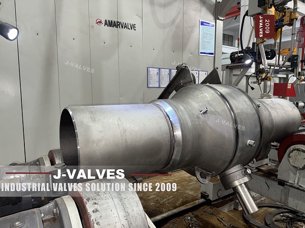
The photograph at the top of this page carries five stamped lines on the shell: the maker's name, the number twelve, the number three hundred, the steel A105 and the code H1262. That is the whole identity of the unit in the picture, and it is more precise than anything in the specification block beside it, which offers three body steels and five forms of operation as if all of them were on the shelf.
The valve is a twelve inch Class 300 welded trunnion ball valve, forged in A105, with butt weld ends and an electric actuator carrying a handwheel. There is no body flange and no bolted cover, so the shell is closed for its life and the only ways in are the top, the drain and the two seat injection ports.
This page reads the valve from the stamp outward. What those five lines fix, what they leave to the certificate, and why a bore described as an exact match to the pipe is a statement about one schedule rather than about the valve.
Design and Construction
The body is welded from a forged pipe section and two forged ends. The ends are machined with the weld preparation first, then aligned, tacked and welded, and the shell is radiographed before anything is bored into it. Forging rather than casting matters here for one practical reason: a forged section has no shrinkage porosity to find later, and a weld made into it is a weld into uniform material.
The ball sits on an upper and a lower trunnion, so the pressure load goes into two bearing shafts and the seats are left with sealing only. At twelve inch and Class 300 that is what keeps the operating torque low enough for a quarter turn actuator, and it is the reason the same size in a floating design does not exist in this range.
The top flange is the one bolted joint left on the assembly, and it is worth naming as such. The body is welded, but the drive is not: eight studs hold the actuator mounting pad to the stem housing, which means the drive can be changed in the field and the stem packing can be reached without cutting the line. A welded body is not a sealed box; it is a box with a lid on the top.
The stamp sits on the body, not on a separate plate, and that is deliberate. A plate can be lost, swapped or painted over. A stamp in the forging survives the coating, the transport and the next twenty years, which is why the first thing a pipeline inspector does on arrival is read the shell rather than the paperwork.
That unpainted view is the clearest argument for welding the shell and bolting the top. The seam is ground flush because it will be coated and because a proud weld under a coating is a holiday waiting to happen. The lug is there because the assembly is lifted as one piece. The drain is piped to the side of the saddle so that it can be reached with a wrench once the valve is set on its foundation.

Five Lines on the Shell
Read line by line, the stamp is a specification compressed to five words. Twelve is the nominal size and with it the bore, the wall and the length. Three hundred is the class and with it the test pressure. A105 is the steel of the shell. H1262 is a code, and the page does not say whether it is a heat number or a serial number, which is the first thing to settle because it is the only handle on the material certificate.
The class line is the one that needs no interpretation. Class 300 is a row in the rating table and it does not depend on what the page says elsewhere. The confusing rows are the two the page presents as choices. A body in A350 LF2 or in A182 F316 is a different valve with a different temperature range and a different price, and the photograph of a unit stamped A105 is evidence of one build, not of three.
| What the Stamp Says | What It Fixes | What You Still Have to Ask |
|---|---|---|
| Twelve | Nominal size, bore, wall and face to face | Which pipe schedule the bore is matched to |
| Three hundred | Class, and the shell and seat test pressures | Nothing, the class is the class |
| A105 | The steel of the shell, forged carbon | Heat treatment, and any impact test required |
| H1262 | The heat or serial number | Which certificate it belongs to |
| J-VALVES | The maker of the shell and the assembly | Who signed the test report |
The bore deserves its own paragraph because the page overstates it. It says the twelve inch full bore matches the pipeline inner diameter exactly, and a full bore valve is indeed bored to the pipe it is ordered for. But the inner diameter of a twelve inch pipe is not one number: it changes with the wall schedule, and a valve bored for one schedule is not an exact match for another. The honest description is that the bore follows the schedule stated on the order.
The last consequence of the stamp is about records rather than geometry. A heat code is only useful if it points at a certificate that carries the same code, the chemical analysis and the mechanical results for that heat. A 3.1 certificate to EN 10204 is the document that does this, and the chain is broken if the code on the shell and the code on the certificate are not compared at goods inward.
Technical Specifications
The table is the build as the photograph shows it, with the options moved to a separate row so that the two are not read as one. The seat range and the body range do not agree at the bottom end, and the lower of the two governs: a seat rated to minus forty six does not make an A105 shell a low temperature valve.
| Item | Value |
|---|---|
| Nominal size | 12 inch, DN 300 |
| Pressure class | Class 300, PN 50 |
| Temperature | Minus 29 to plus 425 Celsius, carbon steel body |
| Body | ASTM A105 forged carbon steel, welded shell |
| Body options | A350 LF2 to minus 46, or A182 F316 as an upgrade |
| Body joints | None, welded shell |
| Ball | A105 with ENP, hard chrome or tungsten carbide |
| Ball support | Upper and lower trunnion |
| Trunnion | Surface hardened A105 or 17-4PH |
| Stem | 17-4PH, or A105 with ENP |
| Stem seal | Graphite packing, wire reinforced |
| Seat | PTFE or RPTFE to 180 Celsius, PPL to 280, PEEK to 260, metal with graphite to 425 |
| Seat design | Single piston effect or double piston effect, named on the order |
| Ends | Butt weld to ASME B16.25, optional flanged transition |
| Operation | Electric quarter turn with handwheel, as photographed |
| Top flange | Bolted pad for gear, electric, pneumatic or hydraulic drive |
| Design | API 6D and ASME B16.34 |
| Test | API 6D and API 598 |
Two rows of that table are written the way the photograph forces them to be written. The operation row names the electric unit with its handwheel, because that is what is on the valve, and not a list of five possibilities. And the body options row sits below the body row rather than inside it, because a choice is not a specification.
The seat range also fixes what the valve can be sold for. Class 300 at minus twenty nine is the standard build, and the low temperature version of this valve is a different body steel with a different certificate. Writing minus forty six into the seat row and leaving the body at A105 is the most common way a data sheet ends up promising a valve that cannot be shipped.
Standards and Compliance
API 6D governs the valve and ASME B16.34 the wall and the ratings, and the two are complementary rather than alternative. The weld ends are cut to ASME B16.25 unless the pipeline specifies its own profile, and the shell and seat tests are to API 598 as called up by 6D.
| Document | What It Fixes | What It Leaves Open |
|---|---|---|
| API 6D | Classes, test, marking, cavity relief | The steel certificate behind the marking |
| ASME B16.34 | Wall thickness and pressure ratings | The weld procedure |
| ASME B16.25 | The weld end profile | The pipe end it will meet |
| API 598 | Shell and seat test method | The acceptance rate for a metal seat |
| EN 10204 3.1 | The certificate that carries the heat number | Whether anyone compares it to the shell |
| NACE MR0175 | Hardness limits for sour service | Whether the service is sour at all |
The certificate line is the one that turns the stamp into a record. A 3.1 certificate is issued by the mill and countersigned by the maker, and it is specific to a heat. Without it the five lines on the shell describe a valve; with it they describe a valve whose steel can be traced to a furnace, which is what a pipeline operator is actually buying.
Sour service is a separate decision and it is not visible on the stamp. NACE MR0175 limits hardness in the shell, the welds and the heat affected zones, and a valve that meets it will normally be marked or certificated separately. A page that lists the option without saying so invites an order that arrives without the documentation the service requires.
Manufacturing Process
The forging comes in as a pipe section and two ends, both machined with the weld preparation before anything is joined. The circumferential welds are made under a qualified procedure by gas metal arc or submerged arc welding, and the shell goes to radiography before the bore is finished, because a defect is cheaper to find in a rough shell than in a finished one.
Machining follows the radiography. The bore, the seat pockets, the stem bore and the trunnion bores are cut in one setting where the size allows, so that the ball sits square to both seats. Then the ports are drilled and tapped: one drain at the lowest point, two injection points at the seats.
Marking is done after machining and before coating, and it is stamped rather than painted. That ordering is not a detail. A stamp applied after coating either damages the coating or is applied to it and lost, and a stamp applied before the final machining can be cut away. The window is narrow and it is the reason the marking on a sound valve is legible twenty years later.
The coating is applied last, with the ends masked. A welded valve with painted weld ends is a valve that will have to be stripped in the field, and the masking is part of the process rather than a convenience.

Quality Control and Testing
Every shell weld is radiographed, and the shell and seat tests follow to API 6D and API 598. The shell test proves the welded body and the two sleeve-free ends; the seat test proves each seat in the direction it is loaded, which for a single piston design is the downstream direction only.
The check that belongs to this page is the identity check. The heat code on the shell is compared with the code on the mill certificate, the certificate is compared with the chemical and mechanical requirements of A105, and the result is filed with the valve. That is a five minute job at goods inward and it is the only thing that makes the stamp worth stamping.
The actuator is tested separately, because it is a bought item on a bolted pad. The travel is set against the valve, the limit switches are set at both ends, and the handwheel is proved to engage and disengage with the drive disengaged. A valve that arrives with the actuator stroked but not set will report closed while the ball is a few degrees short.

Applications and Industry Service
The first use is isolation on a transmission line or in a station, where a twelve inch Class 300 valve is a section boundary and the drive is electric because the site has power and no instrument gas. The welded body suits that duty because there is no joint to leak at and no gasket to replace.
The second use is a buried installation, and there the top flange is the part that decides the maintenance plan. A welded body below ground with a bolted top flange above it can have its packing and its drive reached from a pit; the same body with the ports buried and no pit cannot be injected at all.
The valve is the wrong choice where the line is sour and the certificate cannot be produced, and where the pipe schedule is not settled at the time of order, because the bore is cut to a schedule and cannot be changed afterwards. It is also the wrong choice where the ground moves, since a welded shell transmits settlement into the pipe rather than absorbing it.

Installation, Operation and Maintenance
Installation is a butt weld at each end, made to the pipeline procedure, with the valve in the open position and the bore protected from spatter. The body is supported on its own feet or on a saddle rather than hung from the pipe, because a twelve inch Class 300 shell with an actuator on top is a weight the line should not be asked to carry.
Alignment matters more than usual on a welded valve because there is no flange to absorb a mismatch. The two pipe ends have to be true to the valve bore before the root is made, and a valve pulled into line by its own weld is a valve with a preload in the shell that nobody will ever measure.
Operation is a quarter turn with the handwheel as the manual override, and the two readings worth recording at commissioning are the turns to travel and the motor current at each end. A current that climbs over the first months points at a seat or a bearing; a travel that changes points at the linkage between the actuator and the stem.
Maintenance is limited to the packing, the actuator and the injection ports. The seats cannot be replaced without cutting the body, so the injection ports are the maintenance path: sealant restores a weeping seat, and the drain proves the cavity before any work is done on the line.
How to Specify and Order
The order lines below are the ones the page leaves open, and the first three are the ones that decide whether the delivered valve matches the stamp on it.
| Line on the Order | What to Write | Why It Matters |
|---|---|---|
| Size and schedule | Twelve inch, and the wall schedule of the pipe | The bore is cut to the schedule |
| Class | Class 300 to API 6D | It is a row in the table, not a preference |
| Body steel | A105, or LF2 or F316 if the temperature needs it | The stamp follows the order |
| Heat traceability | EN 10204 3.1, with the heat code compared at receipt | The stamp is only as good as its certificate |
| Seat | PTFE, RPTFE, PPL, PEEK or metal, with the temperature | The range narrows as the temperature rises |
| Seat design | Single or double piston effect | The cavity relief depends on it |
| Ends | ASME B16.25, and the pipe profile if it differs | The two profiles are not the same shape |
| Operation | Electric quarter turn, with the handwheel stated | The photograph is one build, not a menu |
Read as a whole, the page describes a valve whose identity is stamped into it. The class and the steel are fixed at the forge, the bore is fixed at the machine, and the drive is the one part that can still be changed on site. What a buyer needs from the page is not a list of possibilities but the five lines that are actually on the shell, and the certificate that makes them mean something.
FAQ
Q: What do the markings stamped on the body actually tell me?
A: They give the size, the class, the body steel and a code that is either a heat number or a serial number, plus the maker. The first three fix the geometry and the rating, and the fourth is the only route to the material certificate. What they do not tell you is the pipe schedule the bore was cut for, which is why that line has to be on the order.
Q: Is the bore really an exact match to the pipeline inner diameter?
A: Only for the schedule it was bored for. A full bore valve is machined to the inside diameter of the pipe it is ordered against, and that diameter changes with the wall schedule. The same twelve inch valve ordered against two schedules will not have the same bore, so the schedule belongs on the order and not in an assumption.
Q: Can the body steel be changed after the valve is made?
A: No, and that is the point of reading the stamp rather than the data sheet. A105, A350 LF2 and A182 F316 are three different forgings with three different temperature ranges, and the unit in the photograph is stamped A105. The optional steels in the specification block are other builds, not variants of this one.
Q: Why is the top flange bolted if the body is welded?
A: Because the drive has to be changeable and the packing has to be reachable. Welding the shell removes the body joint and the gasket that goes with it, but it leaves the stem housing as an opening, and that opening is closed by a bolted pad. A welded body with a bolted top is not a contradiction; it is the normal arrangement.
Q: How is the heat code used after delivery?
A: It is compared with the code on the EN 10204 3.1 certificate, and the certificate is compared with the chemical and mechanical requirements of the steel. If the two codes do not match, the stamp describes a valve but not a heat, and the traceability the operator is paying for has not been delivered.


Hot Products


News
Urea Plant Ball Valves: The Wetted Path Survives Only While Oxygen Is Being Fed To It
Carbamate at 150 bar and 185 C eats stainless 50 times faster once the passive film starves. The valve cavity is where the oxygen runs out first.
Read More
Stiction: What A Ball Valve Becomes When Nobody Turns It
A valve that stood closed for years has not worn out. The seat has bonded to the ball, and the first stroke is a step, not a ramp. What the trace shows.
Read More
Molten Salt Ball Valves: The Valve Works at 565 C And Dies at 219 C
Salt freezes at 220 C and decomposes at 565 C. Everything a molten salt ball valve does happens in that 345 kelvin gap, and the gap is not generous.
Read More
Direct Air Capture Ball Valves The Vacuum Side Runs The Seal Backwards, And Three Hundred Thousand Strokes Decide The Design
A solid sorbent DAC plant moves 1.3 million cubic metres of air per tonne of CO2, then asks a DN50 ball valve to hold 0.9 bar from the wrong side.
Read More