


CHINA J-VALVES Offers Various High-quality I ndustrial Ball Valves
J-VALVES, a distinguished professional ball valve manufacturer rooted in China, takes pride in its extensive product portfolio. Our offerings span a wide range, including trunnion-mounted ball valves, floating ball valves, high-temperature ball valves, high-pressure ball valves, metal-sealed ball valves, ultra-low temperature ball valves, DBB ball valves, Three-way And Four-way Ball Valve, and fully welded ball valves. Each product is a testament to our commitment to precision engineering and reliable performance. Meticulously crafted, they are designed to not only meet but exceed the most stringent industrial demands, ensuring stable operation even under extreme conditions. This enables us to provide our clients with high-value services and makes our valves widely sought-after in industries.
Product Category
Contact Us

-
J-VALVES-Q647F
-
J-VALVES
Overview of the J-VALVES API 6D fully welded trunnion ball valve, gas hydraulic actuated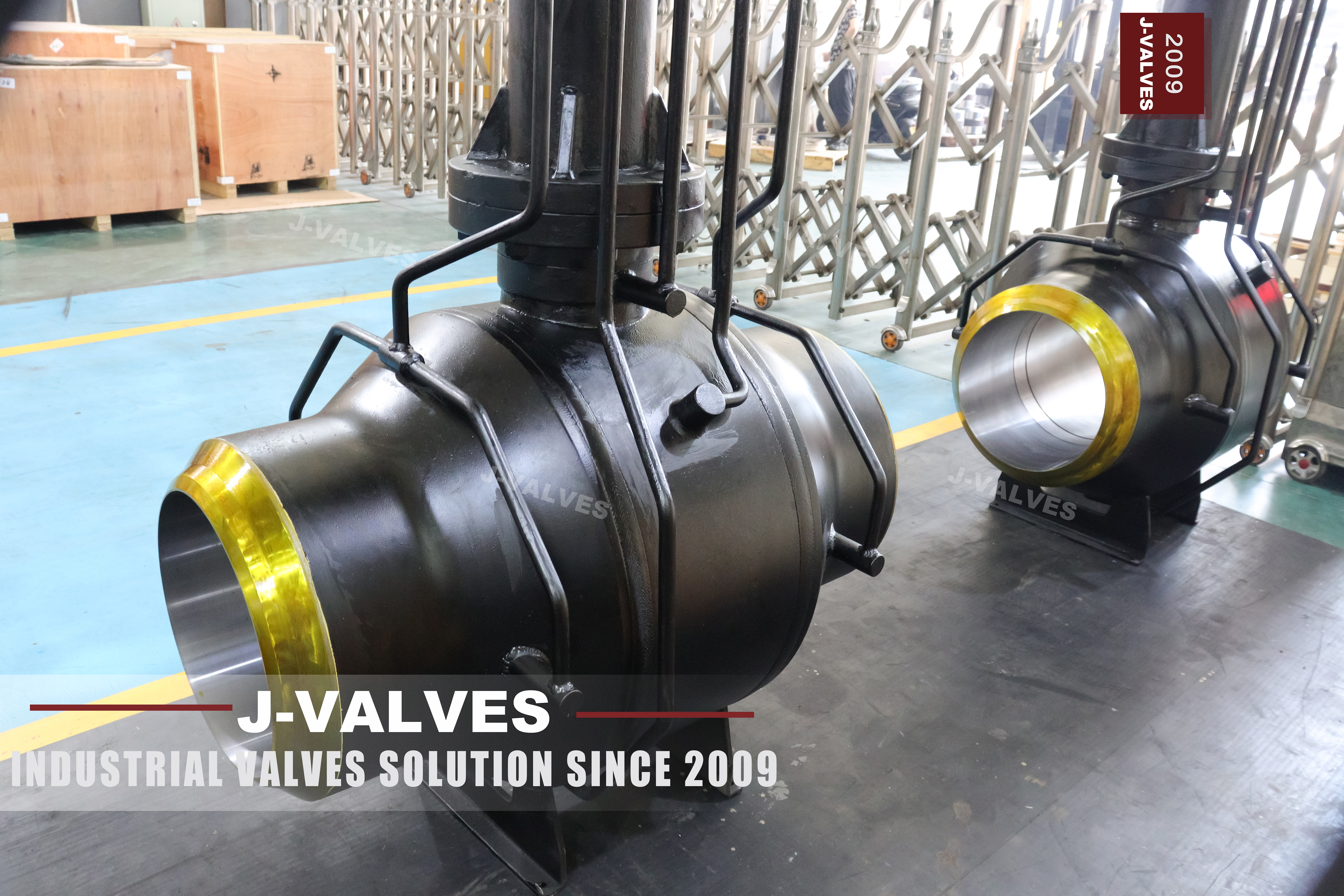
The actuator on this valve has no power supply of its own. It takes gas from the pipeline at half a megapascal to one megapascal, passes it through an intensifier, and uses the resulting hydraulic pressure to turn the ball through its quarter. Nothing is wired to it, nothing is charged from a battery, and there is no instrument air header to run. On a remote section of a transmission line that is exactly what an operator wants.
It is also the one thing about this valve that can strand it. The gas that opens and closes the valve is the gas the valve is there to stop, and every stroke that uses line gas has to put that gas somewhere afterwards. The page describes the arrangement as a feature and moves on; this page stays with it, because the choice between a gas hydraulic unit, an electric actuator and a pneumatic one is a system decision that outlives the valve.
The body underneath is a forged, circumferentially welded trunnion valve from two inch to sixty inch and Class 150 to Class 2500, with butt weld ends to ASME B16.25 as standard and flanged transition pieces on request. None of that is unusual. What is worth reading closely is how the valve is powered, how it behaves when the line it sits on is blown down, and what has to be written on the order for the actuator to still work on the day it is needed.
Design and Construction
The body is built from forged pipe sections and forged end pieces, welded around their circumference. There is no body flange, no bolted cover on the shell, and therefore no gasket that can weep. The two girth welds are full penetration, radiographed after welding, and they are the only places where the pressure boundary is joined rather than machined from one piece. That is the whole argument for a welded body, and it is a good one.
Inside, the ball is carried on an upper and a lower trunnion. The page draws a line between two builds: at four inch and smaller the trunnions are housed in the primary body, and at six inch and larger they are housed in two bearing blocks. The difference matters more than it looks. A trunnion bore cut directly in the body cannot be renewed; a bearing block can be replaced, and the block also lets the bore be machined on a separate setup where the tool reaches it.
The stem is a separate part from the ball and does not carry the side load that line pressure puts on the ball. Two O-rings and a graphite gasket give it a triple barrier at the top, the packing can be renewed with the line live by removing the gland bushing, and the shoulder below the packing is the anti blow out feature that API 6D asks for. A sealant injection fitting is standard on the stem as well.
The seats are the usual three arrangements: single piston effect, double piston effect, and a combination where one seat is SPE and the other is DPE. The page recommends DPE for welded body valves, and its own table says that a DPE seat is not self relieving. Both statements are correct and they point in opposite directions, which is a subject for the section on the cavity rather than this one.

Actuator and Power Supply
A gas hydraulic actuator is a small hydraulic power pack fed by gas. Line gas at half to one megapascal pushes a piston in an intensifier; the hydraulic side of that piston is a much smaller area, so the pressure multiplies and the hydraulic oil drives the actuator cylinder. The gas does not enter the hydraulic circuit. What it does is provide the energy, and it does that without any electrical supply, which is why this arrangement is common where a line has no power.
| Part | What the Page Offers | What Actually Decides It |
|---|---|---|
| Body and ends | A105, A350 LF2, A694 F52 or F65, A182 F316 | The design temperature and the pipe grade it is welded to |
| Ball | A105 with ENP, hard chrome or tungsten carbide, or solid F316 | Whether the medium is dry gas or carries solids |
| Trunnion | Surface hardened A105, or 17-4PH | The seat load and the number of cycles |
| Stem | 17-4PH, or nickel alloy 718 to UNS N07718 | Torque at temperature, and the packing compression |
| Seats | PTFE or RPTFE, PEEK, or metal with graphite | The temperature column, not the preference |
| Packing | Flexible graphite with a nickel alloy wire core | The top of the temperature range |
| Actuator | Gas hydraulic, from line gas or nitrogen | Gas quality, vent destination and stored volume |
| Ends | Butt weld to ASME B16.25, flanged on request | The pipe specification and the tie in method |
The gas supply is taken upstream of the valve. That is deliberate: a closed valve still has pressure on its upstream side, so the actuator keeps its supply after it has closed. What breaks the arrangement is the next step in the sequence. A shut off valve exists so that the section downstream can be blown down, and once that section is empty the actuator on the valve that isolated it can only move again if it has gas from somewhere else.
That is what the accumulator is for, and why it should not be read as an accessory on the option list. A hydraulic accumulator stores enough oil at pressure for a defined number of strokes with no gas supply at all. One stroke is enough to close a valve whose upstream is dead; it is not enough to open it again, close it, and open it again during a maintenance campaign. The volume of the accumulator, not the pressure of the gas, is what sets how many strokes are available with the line dead.
The closing time follows from the same parts. Five to thirty seconds is adjustable because the hydraulic exhaust is throttled, not because the gas pressure is changed; the throttle sets how fast the oil leaves the cylinder. An emergency shutdown in under ten seconds cannot come from gas passing through an intensifier in that time, so it comes from stored hydraulic volume released at once. The page lists both figures as if they were properties of the actuator. They are properties of the actuator plus its accumulator.
Technical Specifications
The table is the build as the page states it, with the actuator row written as an actuator rather than as a benefit. Sizes and classes are quoted as ranges because a two inch Class 150 and a sixty inch Class 2500 are not the same valve and do not share a drawing.
| Item | Value |
|---|---|
| Size range | 2 inch to 60 inch, DN 50 to DN 1500 |
| Pressure class | Class 150 to Class 2500, PN 20 to PN 420 |
| Temperature | Minus 29 to plus 425 Celsius for the carbon steel body |
| Body | Forged carbon steel A105, three girth welds, no body flange |
| Ball | A105 with ENP or carbide coating, or solid F316 |
| Trunnion | In the body to 4 inch, in bearing blocks from 6 inch |
| Stem | 17-4PH or nickel alloy 718, anti blow out, injectable |
| Seat | SPE, DPE or combination, PTFE to metal with graphite |
| Ends | Butt weld to ASME B16.25, flanged transition on request |
| Actuation | Gas hydraulic from line gas or nitrogen, 0.5 to 1 MPa |
| Stroke time | 5 to 30 seconds adjustable, emergency closure under 10 |
| Design and test | API 6D and ASME B16.34, tested to API 6D and API 598 |
Two things in that table deserve a note. The temperature range belongs to the carbon steel body and to the seat that is fitted, not to the valve in general: a metal seat with graphite can go to the top of the range while a PTFE seat stops far below it, and the page prints a single figure over both. And the actuator supply is gas quality dependent. Wet gas, glycol carryover and hydrate forming conditions all reach the intensifier before they reach the ball.
Standards and Compliance
API 6D is the governing document for this valve. It sets the pressure classes, the test requirements, the marking and the fire test expectation, and it is the standard under which a pipeline valve is bought. ASME B16.34 supplies the wall thickness for the material group and the pressure temperature ratings behind each class. ASME B16.25 fixes the weld end profile that the pipe is jointed to, which is the detail that decides whether the field weld is a fit up or a fight.
| Document | What It Fixes | What It Leaves Open |
|---|---|---|
| API 6D | Classes, test, marking, fire test, cavity relief intent | How a welded body relieves its cavity |
| ASME B16.34 | Wall, material groups, ratings against temperature | The internals and the actuator |
| ASME B16.25 | Weld end profile and dimensions | The welding procedure at site |
| API 598 | Shell and seat test procedure | The class of the test |
| API 607 and API 6FA | Fire test of the design | Whether the unit shipped was tested |
| IEC 60079-0 | Temperature class T6 means 85 Celsius surface | The gas quality inside the enclosure |
The actuator's explosion protection is worth reading carefully because it is usually quoted as a single badge. Ex d IIC T6 says the enclosure contains an internal explosion without transmitting it, that it is rated for the gas group that includes hydrogen and acetylene, and that no surface of it exceeds 85 Celsius. The last of those is a limit on the enclosure in still air, and an enclosure painted dark and standing in sun reaches it before the process does.
Manufacturing Process
The pipe sections and forged ends are cut, bevelled, aligned and welded. Alignment is the operation that decides the valve, because the two ends have to be coaxial to the bore and square to each other before the weld is made; a body welded out of line cannot be corrected afterwards, and the seats will show it as one seat carrying more load than the other. The weld is full penetration, and it is radiographed in full rather than by sample.
After welding the body is heat treated if the procedure requires it, then the bore, the seat pockets and the trunnion bores are machined. On sizes from six inch the bearing blocks are separate parts and their bores are cut on their own setup, which is one of the reasons the page distinguishes them from the small sizes where the trunnion runs directly in the body.
The ball and the seat rings are made separately, coated or hardfaced, ground and lapped, and matched before assembly. The stem goes in from the top through the packing housing, the operator mounting pad is machined square to the stem axis, and the whole assembly is tested with the actuator or a test unit fitted so that the stroke can be verified against the limit switches rather than by eye.

Quality Control and Testing
The shell test is applied to the assembled body with the ball open, at the multiple of the class that API 6D names, and the two girth welds are the parts under observation. There are no body joints to watch, which is the point of the design, so a weep during the shell test is a weld defect and not a gasket problem. The radiographs are the record that the weld was sound before the test, and the test is the record that it still is.
The seat test is run from each side. On a DPE build both seats are barriers in both directions, which is what makes a double block and bleed check meaningful; on an SPE build the upstream seat is not a barrier against the cavity, so the test is done from the side that is loaded and the result is read as one seat, not two.
The actuator is set up on the valve, not on a bench. The open and closed positions are set against the mechanical stops, the limit switches are set to those positions, and the stroke time is measured with the specified supply pressure and the specified accumulator charge. A unit that is set up on air and shipped to a gas line with a different supply pressure arrives with its switches out of position, and the first symptom is a valve that reports closed while it is not.

Applications and Industry Service
Transmission lines are the first use, and the gas hydraulic unit is why. A block valve station on a line that has no power is exactly the case this actuator was made for: line gas is available, electricity is not, and the valve has to close on command. The same arrangement is used at city gate stations, at metering runs and at the inlet of a storage field.
The second use is anywhere the valve is expected to close on a signal rather than by hand, and where the isolation is the last barrier before a flare or a vent. That is also the case where the power source deserves the most thought, because a valve that depends on the gas it is isolating will not operate on a section that has already been blown down, and the sequence in an emergency is not always the one drawn on the panel.
Where the valve should not be used is on a line whose gas is wet, sour or dirty beyond what the intensifier and the seals will tolerate, unless the supply is taken from a clean nitrogen bottle instead. It is also the wrong choice where the vent of the actuator cannot be routed to a safe location, because every stroke that uses line gas puts that gas out of the exhaust.

Installation, Operation and Maintenance
The valve is welded into the line, so installation is a welding procedure, a fit up check and a radiograph of the field joints, not a flange make up. The body is supported so the pipe does not hang from the shell, and the actuator is left with room for its exhaust and its hand pump to be reached without removing anything. The gas supply line to the actuator is a small bore tube with its own isolation and filter, and it should be installed so that it can be isolated without shutting the main line.
Operation is a quarter turn and the actuator does it in seconds, which makes the valve feel simpler than it is. The two positions that matter are the mechanical stops, and both should be checked against the ball position at commissioning rather than against the switch indication. A valve that has been set to stop on the switch will slowly lose travel.
Maintenance on the body is limited to what can be reached without cutting it out: the stem packing, the seat injection fittings and the drain. The page promises a maintenance free life of fifty years, and that figure is a statement about the shell, not about the actuator. The intensifier seals, the hydraulic hoses and the accumulator precharge are the parts that will be attended to first, and they are all above ground.
How to Specify and Order
The order lines below are the ones the page leaves open, and the first is the one that decides whether the valve can still be operated after the section it isolates has been emptied.
| Line on the Order | What to Write | Why It Matters |
|---|---|---|
| Actuator power source | Line gas, nitrogen bottle, or instrument air, with the pressure band | The valve's ability to move depends on this |
| Stored volume | Accumulator size and the number of strokes required with the supply dead | One stroke is not a maintenance campaign |
| Vent destination | Where the actuator exhaust is piped, and whether it is captured | Every gas powered stroke puts gas out |
| Stroke and emergency time | Normal time, and the emergency time with the accumulator only | The two come from different volumes |
| Seat arrangement | SPE, DPE or combination, per seat, in writing | The two behave differently on cavity pressure |
| Body material and ends | Grade, weld end profile, and the pipe grade it joins | The field weld is made to one of them |
| Stem and packing | Alloy designation to UNS, not a trade name | The brand says who made it, not what it is |
| Class and test | Class to API 6D with the test pressure and duration | The class on the plate is a tested class |
Read as a whole, the page describes a valve whose body is the least interesting part of the decision. The welded shell, the trunnion and the butt weld ends are all settled practice at this size and class. What separates a valve that works from a valve that does not is whether the actuator was specified as a system with a power source, a stored volume and a vent, or as a badge on a drawing.
FAQ
Q: Where does a gas hydraulic actuator get its power?
A: From the pipeline. Line gas at half to one megapascal enters an intensifier, the hydraulic side of the intensifier is much smaller in area, and the resulting oil pressure drives the cylinder. No electricity and no instrument air are involved, which is why the arrangement is used on sections of line that have neither.
Q: What happens to the gas that was used to move the valve?
A: It is exhausted. The gas side of the intensifier has to return to its starting position before the next stroke, and the gas that pushed it is vented at the exhaust. On a valve that strokes a few times a year this is small; on a valve that is cycled often it becomes a reported quantity, and the exhaust has to be piped somewhere safe or captured.
Q: Why does the valve need an accumulator if the gas is always there?
A: Because the gas is taken upstream of the valve, and the reason the valve exists is that the section downstream will be emptied. After a blow down the upstream side may still be live, but once the isolated section is depressurised and the upstream is later isolated too, the actuator has no supply. The accumulator supplies the strokes for that period, and its volume sets how many.
Q: Can the valve close in under ten seconds from line gas alone?
A: Not through an intensifier. Raising hydraulic pressure from a gas supply takes time, and the ten second figure comes from releasing stored hydraulic volume rather than from generating it. That is why the emergency time and the normal time are two different numbers on the same actuator.
Q: Is Ex d IIC T6 the same as a gas tight enclosure?
A: No. It says the enclosure will contain an internal explosion, that it is rated for the gas group that includes hydrogen, and that no surface exceeds 85 Celsius. It says nothing about where the exhaust of the actuator goes, and the exhaust is where the gas actually leaves.


Hot Products


News
Urea Plant Ball Valves: The Wetted Path Survives Only While Oxygen Is Being Fed To It
Carbamate at 150 bar and 185 C eats stainless 50 times faster once the passive film starves. The valve cavity is where the oxygen runs out first.
Read More
Stiction: What A Ball Valve Becomes When Nobody Turns It
A valve that stood closed for years has not worn out. The seat has bonded to the ball, and the first stroke is a step, not a ramp. What the trace shows.
Read More
Molten Salt Ball Valves: The Valve Works at 565 C And Dies at 219 C
Salt freezes at 220 C and decomposes at 565 C. Everything a molten salt ball valve does happens in that 345 kelvin gap, and the gap is not generous.
Read More
Direct Air Capture Ball Valves The Vacuum Side Runs The Seal Backwards, And Three Hundred Thousand Strokes Decide The Design
A solid sorbent DAC plant moves 1.3 million cubic metres of air per tonne of CO2, then asks a DN50 ball valve to hold 0.9 bar from the wrong side.
Read More