

CHINA J-VALVES Offers Various High-quality I ndustrial Ball Valves
J-VALVES, a distinguished professional ball valve manufacturer rooted in China, takes pride in its extensive product portfolio. Our offerings span a wide range, including trunnion-mounted ball valves, floating ball valves, high-temperature ball valves, high-pressure ball valves, metal-sealed ball valves, ultra-low temperature ball valves, DBB ball valves, Three-way And Four-way Ball Valve, and fully welded ball valves. Each product is a testament to our commitment to precision engineering and reliable performance. Meticulously crafted, they are designed to not only meet but exceed the most stringent industrial demands, ensuring stable operation even under extreme conditions. This enables us to provide our clients with high-value services and makes our valves widely sought-after in industries.
Product Category
Contact Us


-
J-VALVES-Q347F
-
J-VALVES
Overview of the J-VALVES high pressure trunnion mounted ball valve range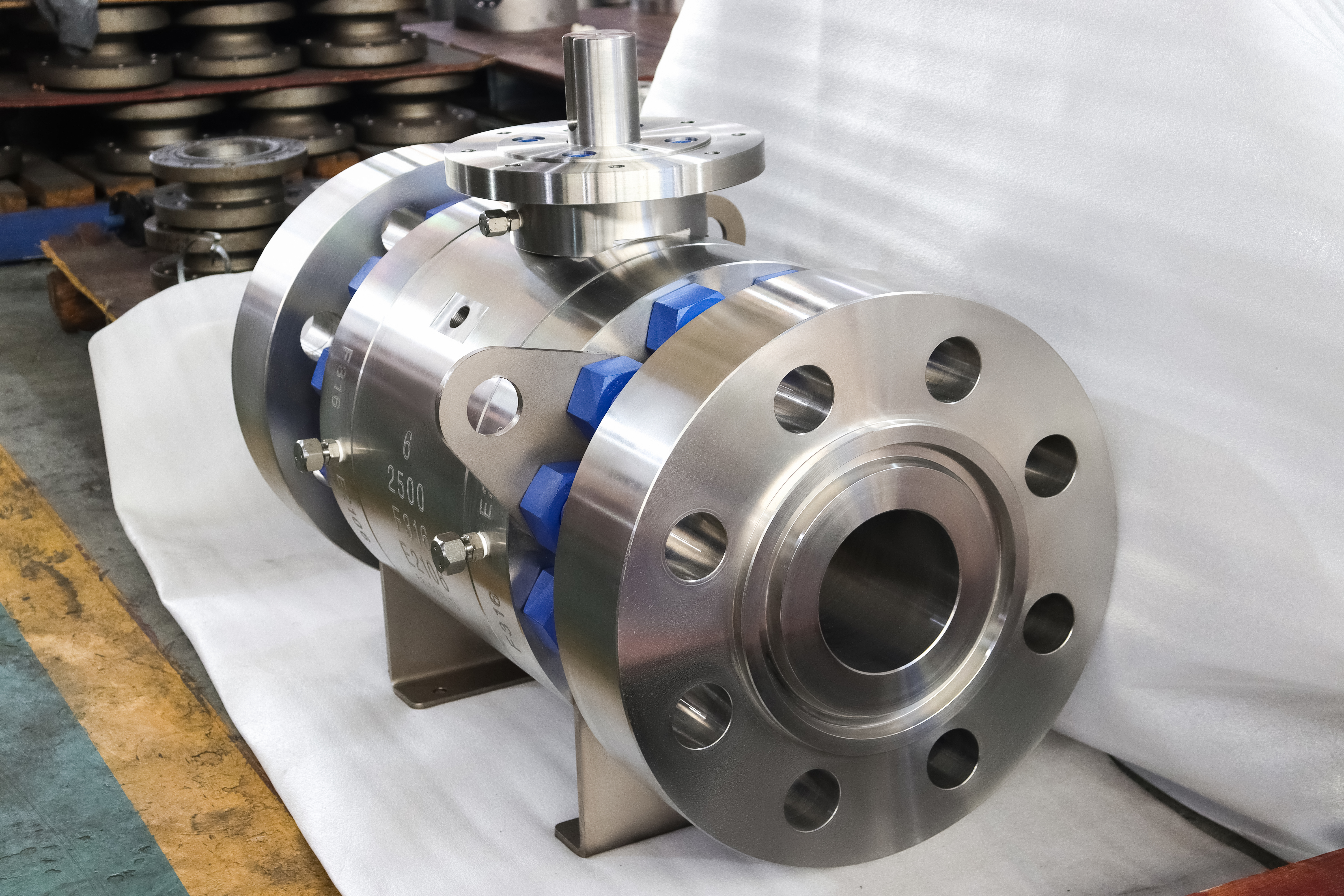
Two inch to fifty six inch, Class 150 to Class 2500, in 316 stainless with a polymer seat and a raised face flange. Read as one sentence, that is a product range. Read against the flange standards, the seat materials and the rating tables, it is four different valves, and three of them cannot be built to the sentence as written.
The photograph is the top of the range and it is worth reading before the table. The marks cast into the body are the class and the grade, the body is in three pieces with bolted joints at both ends, and the operator is a bevel gearbox with a chainwheel rather than a handwheel on a stem. That is what a Class 2500 stainless valve looks like when it is built.
The argument here is that a catalogue range is a statement about what a factory can make, not a statement about any one valve. The four places where this span breaks are the seat, the flange, the rating curve and the operator, and each of them is decided by a different document.
Design and Construction
The construction is a three piece body with a trunnion mounted ball: a centre section carrying the ball, the seats and the stem, and an end piece bolted to each side. Both joints carry line pressure. The ball is held on an upper and a lower trunnion in bearings, so the thrust from the differential pressure goes into the body instead of into the seats.
At the top of the class range the trunnion is not a refinement, it is the reason the article exists. A floating ball at Class 2500 would press on the downstream seat with the whole differential, and the seat ring would have to be a bearing as well as a seal. Putting the ball on trunnions takes that load out of the seat and leaves it with only the sealing job.
The body in the photograph carries two support feet under the centre section. On a valve of this mass they are not decoration: the body is supported so that the pipe is not asked to carry it, and the feet are positioned so that the valve sits on a structure rather than hanging from its flanges. A large valve installed without them puts its own weight into the body joints.
The operator is the part that changes most across the range and the part that is described least accurately. A two inch valve has a lever, a mid size valve has a handwheel through a gearbox, and a Class 2500 valve of any size has a geared operator with a chainwheel or an actuator, because the torque at the seat is beyond what a person can apply directly.
The end connections are the first place the range breaks, and it breaks at twenty four inch. Below that size a raised face flange to ASME B16.5 is available in every class up to 2500. Above it the flange is an ASME B16.47 item, and that standard goes to Class 900 and stops. A flanged Class 1500 or 2500 valve above twenty four inch has no standard flange to bolt to.
The seat is the second break and it is the one that is most often glossed over. The table on this range offers PTFE and reinforced PTFE across the whole span. A polymer seat ring has a compressive limit, and at Class 2500 the seat load per unit area on a ring that size is beyond what the polymer will carry: it extrudes rather than seals, and it does so quietly.

Material Options
The material list on this range is short, which is a virtue and also a limitation. Body, ball and stem are all 316, so the wetted path has one corrosion behaviour and one welding procedure. That is exactly right for chemical and process water duty, and it is not a substitute for a duplex or a nickel alloy where the chloride level or the temperature asks for one.
| Grade | Family | Where It Belongs |
|---|---|---|
| 316 | Austenitic stainless, Mo bearing | The standard build, group 2.2 in B16.34 |
| 316L | Austenitic stainless, low carbon | Welded bodies, where carbide precipitation matters |
| 304 | Austenitic stainless | Mild duty, where chlorides are absent |
| Duplex | Ferritic austenitic | Chlorides with stress corrosion risk |
| Carbon steel | WCB or A105 | Where stainless is not needed and cost decides |
| Alloy steel | Chrome moly | Temperature duty above the stainless ceiling |
The single grade is worth defending before it is criticised. One grade through the body, the ball and the stem means one heat treatment, one passivation procedure and one corrosion behaviour at the seat band, which is where a mixed material build goes wrong. A 316 body with a different ball grade is a galvanic pair sitting in the medium.
It is also worth knowing where 316 stops. The grade is good in chlorides at moderate temperature and it is not good in chlorides at high temperature under stress, where chloride stress corrosion cracking starts. A range page that offers 316 from two inch to fifty six inch and from Class 150 to 2500 is offering a material that is right for most of that span and wrong for part of it.
The pressure capability of 316 is not the limit at the top of the range. In ASME B16.34 group 2.2, Class 2500 is six thousand pounds at 38 Celsius, roughly 414 bar, and the austenitic stainless wall can carry it. What cannot carry it at that class is the polymer seat and, at the very top of the size range, the flange drilling.
Technical Specifications
The class number is the most misread figure on a page like this, because it is a curve and not a pressure. Class 2500 is six thousand pounds at 38 Celsius for this material group and less at every temperature above that. The temperature ceiling of the range and the class of the range have to be read together, and the lower of the two decides what the valve can actually do.
| Item | Value |
|---|---|
| Size range | Two inch to fifty six inch, DN 50 to DN 1400 |
| Pressure class | Class 150 to Class 2500, PN 20 to PN 420 |
| Build shown | Class 2500, F316, three piece body |
| Body, ball, stem | 316 stainless as the standard build |
| Rating | ASME B16.34 group 2.2, 6000 psi at 38 C |
| Seat | Polymer at the lower classes, metal at the top |
| Ends | Raised face to B16.5 to 24 inch, B16.47 above |
| Ends above Class 900 | Butt weld, because B16.47 stops at 900 |
| Face to face | ASME B16.10 where tabulated |
| Temperature | Minus 46 to plus 200 Celsius, seat limited |
| Operator | Lever at small sizes, gear and chainwheel above |
| Body joints | Two, one at each end piece |
| Packing | PTFE or graphite, by temperature |
| Design | ASME B16.34, API 6D, API 608 to Class 600 |
| Test | API 598, or ISO 5208 with a stated rate |
The API 608 reference needs narrowing on this range. That standard covers ball valves from DN 15 to DN 600 in Class 150 to Class 600, so it covers the bottom left corner of this table and none of the top right. A Class 2500 valve is an API 6D article, and quoting 608 for it is quoting a standard that does not reach the class.
The test row has the same problem in a different form. API 598 and ISO 5208 both describe a pressure test, and they do not use the same acceptance language: ISO 5208 sets out leakage rates from the tightest to the loosest, and API 598 sets a permitted leakage by size and by seat type. Naming the standard without naming the rate leaves the acceptance to the works.
Standards and Compliance
| Requirement | Document | What It Means Here |
|---|---|---|
| Product requirements | API 6D | The standard that covers the whole range |
| Product requirements | API 608 | Only to DN 600 and Class 600 |
| Wall and rating | ASME B16.34 | Group 2.2 for 316, group 1.1 for carbon steel |
| Flanges to 24 inch | ASME B16.5 | Every class to 2500 |
| Flanges above 24 inch | ASME B16.47 | Series A and B, and only to Class 900 |
| Face to face | ASME B16.10 | Tabulated lengths, per size and class |
| Pressure test | API 598 or ISO 5208 | Different acceptance languages |
| Material certificate | EN 10204 3.1 | Heat number for each pressure part |
The flange row is the one that decides the shape of the range, and it is worth stating as a table of its own in the buyer's mind. Below twenty four inch, flanged in any class. Above twenty four inch, flanged only to Class 900. Above twenty four inch and above Class 900, butt welded, because there is no standard flange to make. That is not a manufacturing preference; it is what the standards contain.
The face to face row is the quiet one. ASME B16.10 tabulates a length for each size and class, and the length changes with the class and with the pattern. On a large valve the difference between a tabulated length and a drawing length is a spool that has to be remade, so the figure to order against is the one on the drawing and the standard is only a cross check.
Manufacturing Process
The three piece body means two end pieces and one centre section, and on a large valve each of those is a substantial casting or forging in its own right. The two end pieces are usually identical, which is the economy of the construction: one pattern, one machining programme, and a spare part that fits either end.
Machining on a body of this size is done on a large horizontal machine with the seat pockets, the joint faces and the flange facing referenced to one centreline. The seat pockets in the centre section have to be coaxial with each other and square to both joint faces, because the two end pieces close onto those faces and any error is transferred straight into the seat contact.
The stainless route adds the passivation step and the cleaning that goes with it. Every machined surface is passivated after the last cut and after any weld repair, and the body is cleaned and capped before assembly. On a valve that will carry chemical duty, a body that has been machined and left unpassivated is a body with a surface that will pit before the seats wear.

Quality Control and Testing
The test schedule for a large valve is the same in outline as for a small one and different in what it costs to get wrong. A shell test on a fifty six inch body is a lot of water under pressure, and a seat test that fails at that size is a strip down rather than a seat change. That is why the dimensional checks come before the pressure test on this range.
| Step | Check | Acceptance |
|---|---|---|
| 1 Incoming | Heat number against the mill certificate | Chemistry and mechanicals |
| 2 Identity | Positive material identification on body and trim | Grade match |
| 3 Machining | Seat pockets coaxial, square to joint faces | Drawing figures |
| 4 Passivation | Record after machining and after repair | By procedure |
| 5 Shell test | Body and both body joints at 1.5 times | API 598, no leakage |
| 6 Seat test | Each of the four seats, each direction | Rate named on the order |
| 7 Operator | Gearbox and chainwheel function under load | Fitted and set |
| 8 Marking | Size, class, grade, standard | API 6D marking |
The seat test row is where the four seats come from. A three piece trunnion valve with two seats has four seat faces, two per seat ring, and each is tested in the direction it has to hold. A test record that reports one result for the valve has not reported the seats.
The operator row is on the test schedule rather than at dispatch because a geared valve that has been set up badly will pass a pressure test and fail in service. The gearbox is run through its travel under load, the chainwheel is checked for the chain it will carry, and the limit positions are set to the ball's actual open and closed positions rather than to the gearbox's internal stops.

Applications and Industry Service
The duty is high pressure process water, chemical feed, gas letdown and the isolation points on a unit where the pressure is above what a soft seated floating valve can hold. In all of those the trunnion and the metal seat at the top of the range are what make the valve possible, and the 316 body is what makes it survive the medium.
The second duty is large bore isolation on a line that has to be operated from a platform rather than from a hand. That is where the gearbox and the chainwheel in the photograph come in: the operator is part of the specification, not an accessory, and the space needed to pull a chain is a layout question for the piping designer.
It is the wrong range to buy from without narrowing. A buyer who orders from the top of the table gets a Class 2500 stainless valve with a geared operator and a butt weld end, and a buyer who needs a two inch Class 150 valve on a water line gets none of that. The range is a catalogue statement and the order is a specification.
Installation, Operation and Maintenance
Support the body before the flanges are made up, and set the feet on the structure rather than packing under them after the joint is tight. On a large valve the sequence decides whether the body joints end up carrying the pipe's weight, and a joint that carries weight will weep at the gasket under thermal cycling even if it passed its shell test.
Operate through the full travel at commissioning with the line at pressure, and record the gearbox input torque in both directions. On a geared valve the input torque is the only number an operator can read, and a rise between commissioning and the first year is the earliest warning of a seat that is loading up.
For maintenance the line is isolated and vented, both body joints are opened, and the centre section is lifted out with the ball and the seats. On a valve of this size the lift is a rigging operation with a marked mass and marked lifting points, and the drawing is the document that gives both. The seat rings are replaced as pairs and the body gaskets renewed.
How to Specify and Order
Six decisions define the article: size, class, body grade, seat material, end connection and operator. On this range the sixth line is where most orders go wrong, because a valve specified as manual can arrive with a lever, a handwheel or a chainwheel and only one of those is what the site expects.
Four things belong on the order because the range table cannot carry them. The seat material at the class being ordered, since a polymer seat and a Class 2500 body are not a pair. The flange standard at the size being ordered, because above twenty four inch it changes. The test standard and the acceptance rate, since the two standards do not use the same language. And the operator type with its mounting, because a gearbox pad is a machining feature and not an accessory.
Documents to name: the EN 10204 3.1 certificate with a heat number for the centre section and both end pieces, the positive material identification report, the passivation record, the shell test with each body joint reported, the seat test with a result per seat face, the operator setting record, and the general arrangement drawing with the face to face, the mass and the lifting points.
FAQ
Q: Can a class 2500 valve have a PTFE seat?
A: Not usefully. The class sets the seat load, and a polymer ring at that load extrudes rather than seals. The range table that offers PTFE across the whole span is a statement about what can be made at the bottom of the range; the top of the range is a metal seat.
Q: Why can a fifty six inch valve not be flanged at class 2500?
A: Because there is no standard flange to bolt it to. ASME B16.47 covers twenty six inch to sixty inch and stops at Class 900, so above twenty four inch and above Class 900 the connection is a butt weld. That is a limit of the standards, not a preference of the works.
Q: Is Class 2500 the same pressure at every temperature?
A: No. Class is a rating curve. Six thousand pounds at 38 Celsius for group 2.2 is the first point on it, and the rating falls as the temperature rises. A valve quoted by class alone has had its pressure specified and its temperature left open.
Q: Does API 608 cover this range?
A: Only the bottom left corner. API 608 runs from DN 15 to DN 600 in Class 150 to Class 600, so it covers a two inch Class 150 valve and none of the Class 2500 articles. Above Class 600 the article is API 6D.
Q: Why does a large valve have a chainwheel rather than a handwheel?
A: Because the torque at the seat at that class is beyond what a person can apply on a wheel of a usable diameter. The gearbox multiplies it and the chainwheel lets the operator stand where the wheel is reachable, which makes the chain run a layout question for the piping designer.



Hot Products


News
Why A Ball Valve Gets Harder To Turn: Five Causes, And The Test That Tells Them Apart
A ball valve that stiffens over months points at one of five parts. Measure torque with the line pressurised and again vented, and the split becomes visible.
Read More
The Ball Valve at Four Thousand Bar: Seat Load, Erosion And Fatigue in Waterjet Circuits
At 4,000 bar a 10 mm bore puts 31 kN on the seat and a 0.1 mm leak cuts steel. What a ball valve must survive in a waterjet or intensifier circuit.
Read More
Large Diameter Ball Valves: Four Limits That Change The Design
Above a certain size a ball valve stops being a scaled one. Ball weight, operator torque, body split and the test bench each set a limit at a different size.
Read More
Cast Or Forged Ball Valve Body, And What A Radiography Acceptance Level Actually Buys You
Casting or forging is only half the decision. What RT, UT, MT and a proof test each find in a ball valve body, and where the geometry defeats all of them.
Read More