

CHINA J-VALVES Offers Various High-quality I ndustrial Ball Valves
J-VALVES, a distinguished professional ball valve manufacturer rooted in China, takes pride in its extensive product portfolio. Our offerings span a wide range, including trunnion-mounted ball valves, floating ball valves, high-temperature ball valves, high-pressure ball valves, metal-sealed ball valves, ultra-low temperature ball valves, DBB ball valves, Three-way And Four-way Ball Valve, and fully welded ball valves. Each product is a testament to our commitment to precision engineering and reliable performance. Meticulously crafted, they are designed to not only meet but exceed the most stringent industrial demands, ensuring stable operation even under extreme conditions. This enables us to provide our clients with high-value services and makes our valves widely sought-after in industries.
Product Category
Contact Us


-
J-VALVES-Q47F
-
J-VALVES
Overview of the J-VALVES eight inch Class 300 WCB two piece trunnion valve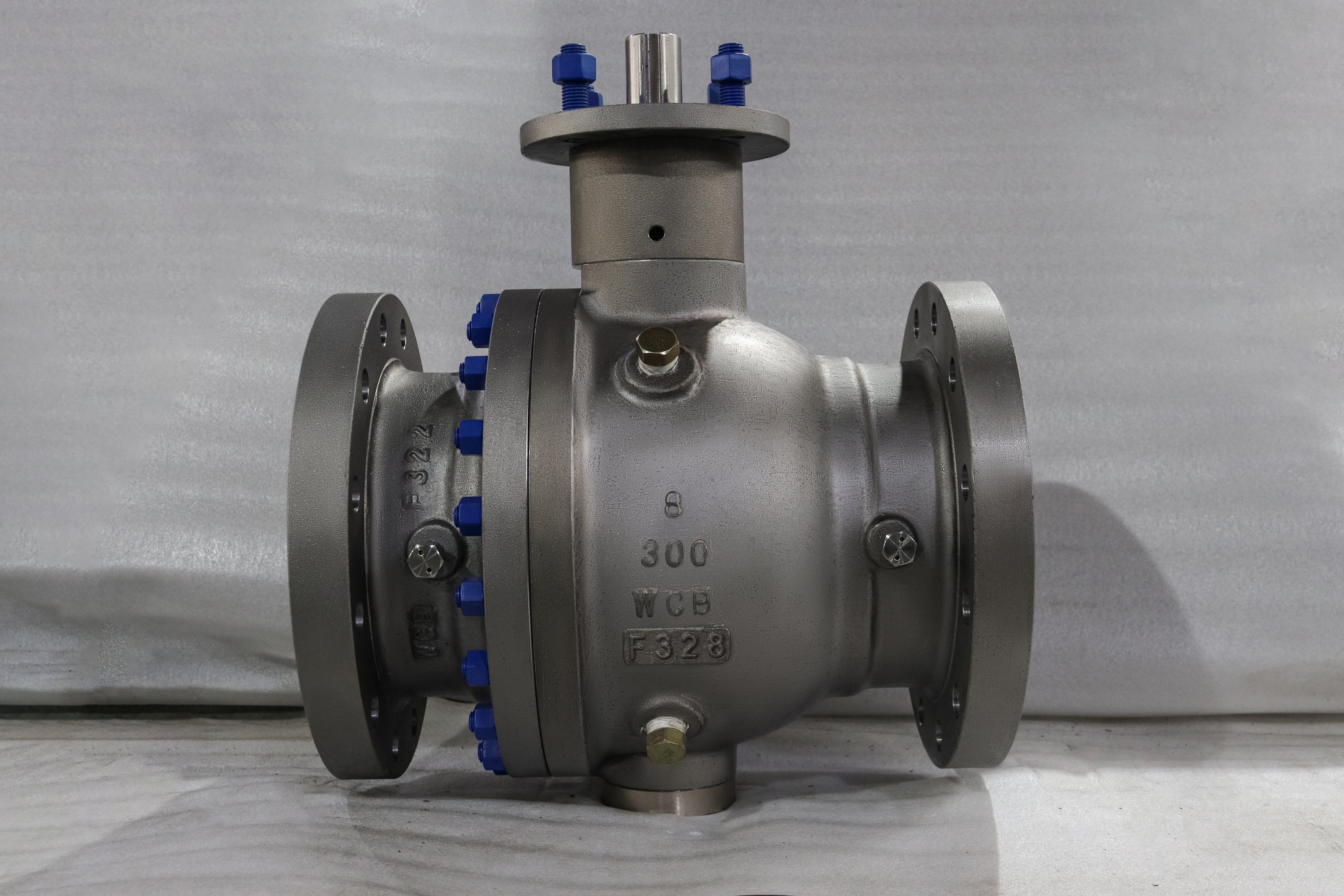
The article name says top, and the photograph shows a small round pad with four studs sitting on a neck above a body whose bore is eight inch. Those two facts do not fit together, and settling which one is right is the whole of this page. A top entry valve is one whose ball comes out through an opening in the top of the body. On this valve the top opening is sized for a stem, a packing set and a gearbox pad.
The build is eight inch, Class 300, cast carbon steel to A216 WCB, in a two piece body with a trunnion mounted ball, from minus 29 to plus 425 Celsius. The photograph carries the four marks that matter cast into the body itself: the size, the class, the grade, and a fourth figure that is a works number rather than a standard designation.
The argument here is that the word top describes where the operator sits, not where the ball goes in. That distinction decides how the valve is maintained, what has to be disconnected to change a seat, and whether the article is the right one for a line that cannot be taken out of service.
Design and Construction
The body is in two pieces: a main body with one end flange formed on it, and a separate end piece bolted to the other side. There is one gasketed body joint and it carries line pressure. That is the only route into the trim, and it is on one side only, which is the practical difference between this article and a three piece body where both ends open.
Look at the bore in the end view and then look at the pad on top. The opening at the end is large enough for the ball to pass through it, which is why the end piece can be unbolted and the ball withdrawn that way. The pad on top is smaller than the stem housing it caps, and no ball of any useful size will pass through it.
That is the general rule behind the naming, and it is worth stating because it explains why two piece valves are sometimes called top entry. When the ball is larger than the end bore, which is what a reduced bore body looks like, the ball cannot be inserted from the end and the body must open at the top instead. On a body where the end bore will pass the ball, the end joint is the way in and the top is only a bonnet.
The ball is held on an upper and a lower trunnion in bearings, so the end thrust from the line pressure goes into the body rather than into the seats. The two seats are then only asked to seal against the pressure that reaches them, which is what makes a trunnion valve practical at Class 300 in eight inch where a floating ball would need a much heavier operator.
Two small hex fittings sit on the body, one above the joint and one below. On a build of this kind they are sealant injection points, used to restore a seat seal in an emergency without taking the line down. They are not a substitute for a seat that was made properly, and a works that offers them as a feature is describing a repair route rather than a design improvement.
The operator is not fitted in the photograph, and the four studs on the pad are the reason. That pad is the mounting interface for a gearbox or an actuator, and the stem above it is left bare on a valve that will be geared at the works or on site. On an eight inch Class 300 valve a lever is not offered, because the torque at this size belongs to a gear.
Material Options
The body is A216 WCB, which is the cast carbon steel grade for this duty and the grade cast into the body in the photograph. The page lists A105 as an alternative, and that is the forging rather than the casting, so it belongs to a different body route for the same duty rather than to a different material property.
| Grade | Family | Where It Belongs |
|---|---|---|
| A216 WCB | Cast carbon steel | The body in the photograph, general service |
| A105 | Forged carbon steel | The same duty on a forged body route |
| WCC | Cast carbon steel, higher strength | Heavier sections and higher stress |
| CF8 | Austenitic stainless casting | Mild corrosion, where carbon steel is not enough |
| CF8M | Austenitic stainless casting, Mo bearing | Chlorides and process gas |
| A105 with ENP | Coated carbon steel | Ball and stem, wear resistance at low cost |
The two carbon steel options are not interchangeable in practice because one is cast and one is forged, and the choice between them is made by size and by the shape of the body rather than by a property table. At eight inch the casting is the ordinary route and the forging is the exception bought for a particular reason.
The ball in a WCB valve is normally carbon steel with an electroless nickel coating, and on this article that is what the trim list leads with. The coating is the wear surface and the corrosion barrier at once, so its thickness and its adhesion are the properties to specify. A ball with a coating that is too thin wears through at the seat band first, and the failure looks like a seat problem rather than a ball problem.
The fourth mark on the body is worth a sentence because it is the one that gets misread. A216 defines WCB; it does not define the figure beside it. Whatever that figure records, it is a works reference and not a grade, and quoting it in a material field is how a carbon steel valve ends up described as something it is not.
Technical Specifications
Class 300 at ambient temperature is 51.1 bar for the carbon steel group in ASME B16.34, and the 5.0 MPa that appears in trade literature for this class is that figure rounded down. Both statements describe the same valve, and the reason to prefer the standard is that the rating falls as the temperature rises, so a single round number cannot describe the whole service range.
| Item | Value |
|---|---|
| Size | Eight inch, DN 200 |
| Pressure class | Class 300, PN 50 in the API 6D table |
| Rating at 38 Celsius | 51.1 bar, ASME B16.34 group 1.1 |
| Temperature | Minus 29 to plus 425 Celsius |
| Body | A216 WCB cast carbon steel |
| Ball | A105 with electroless nickel, or stainless |
| Stem | F6a, F304 or F316 |
| Seat | Reinforced PTFE, PPL, or metal |
| Studs | The B16.5 figure for the flange, twelve at this size |
| Ends | Raised face or ring joint to ASME B16.5 |
| Face to face | ASME B16.10 for eight inch Class 300 |
| Body joints | One, at the end piece |
| Sealant | Injection fittings on the body |
| Operator | Gearbox or actuator on the four stud pad |
| Test | API 598 shell and seat |
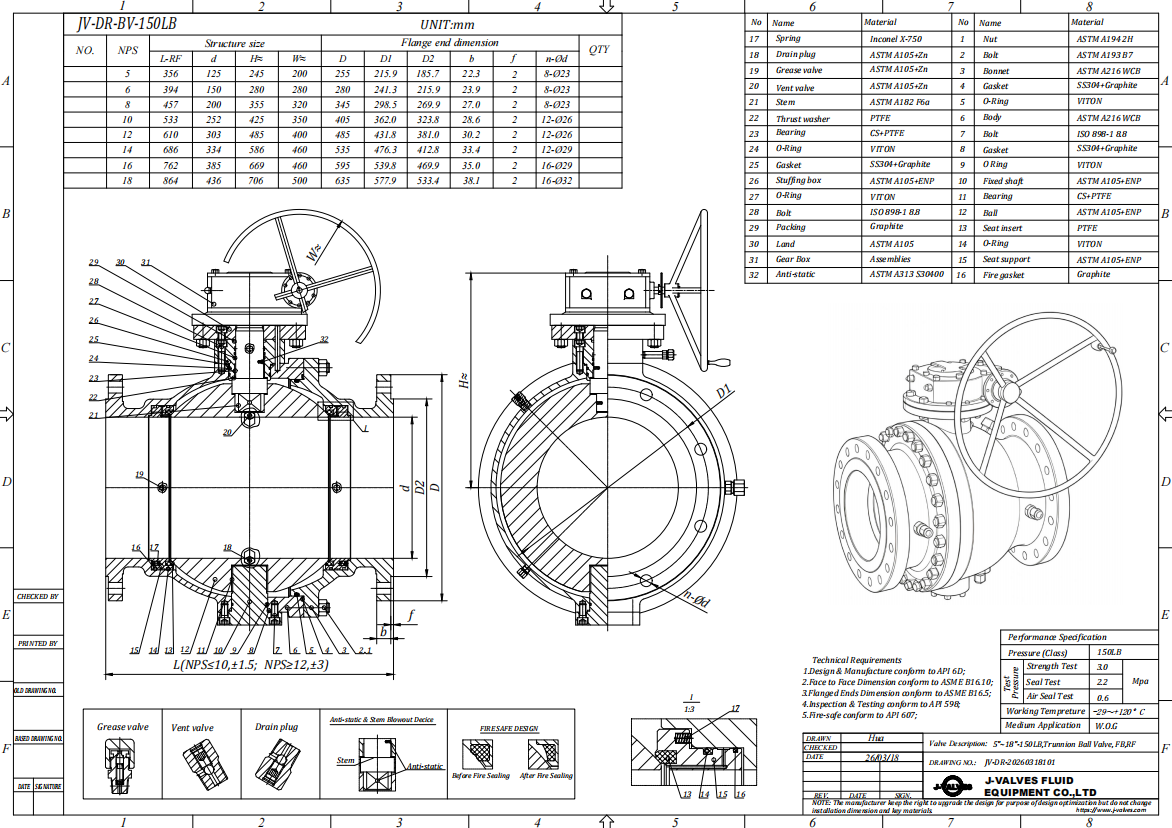
The bolt row is the one that gets checked first on site. An eight inch Class 300 flange in ASME B16.5 carries twelve bolts, and a valve drilled for a different count is a valve that will not mate with the pipe however well the faces line up. The count belongs on the drawing and on the purchase order, and it is faster to check there than in a pipe rack.
The face to face row is a B16.10 figure because this is a single valve body, and that is one place where the two piece construction and the top pad make no difference at all. A valve that is given a B16.10 length can be dropped between two flanges, which is the point of the standard, and an eight inch Class 300 body is inside its scope.
Standards and Compliance
| Requirement | Document | What It Means Here |
|---|---|---|
| Product requirements | API 6D | Design, materials, marking |
| Product requirements | API 608 | Ball valves DN 15 to DN 600, Class 150 to 600 |
| Wall and rating | ASME B16.34 | Group 1.1 for WCB and A105 |
| Casting quality | MSS SP-55 | Visual acceptance levels |
| Pressure test | API 598 | Shell at 1.5 times, seat at 1.1 times |
| Fire test | API 607 or ISO 10497 | Type test with a stated scope |
| Flange drilling | ASME B16.5 | Twelve bolts at this size and class |
| Material certificate | EN 10204 3.1 | Heat number per pressure part |
MSS SP-55 is the row that is usually missing from a specification and usually present on a good casting. It defines the visual imperfections in a casting and grades their severity, so a buyer who names a level is buying a body judged against a published scale rather than against an inspector's opinion on the day. On an eight inch cast body that line is worth more than it looks.
Neither product standard distinguishes a top entry body from a two piece end entry body. API 6D and API 608 set requirements for the body, the joints, the stem, the seats and the tests, and a valve that meets them is conforming whichever way the trim is inserted. A quotation that claims one body style is required is quoting a preference as a rule.
Manufacturing Process
The body is cast, which means a pattern and a core for each piece and a gating system that decides where the metal solidifies last. On this body the heavy sections are around the seat pockets and the flanges, and the last metal to freeze is where porosity will be if the feeders are wrong. That is why the casting route carries a radiography or a visual acceptance level as a scope rather than as an extra.
Machining is done with the two flange faces, the body joint face and the seat pockets referenced to one centreline. The joint face and the seat pocket on the end piece have to be square to each other within a tolerance that is a drawing figure, because the seat ring sits in one and the ball bears on it while the other controls where the joint closes.
The weld repair question belongs here rather than in a sales document. A cast body can be repaired by welding, the repair is allowed by the specification within limits, and the heat treatment after repair is a recorded step on a carbon steel body. A body with a repair and no stress relief record is a body with an unrecorded thermal history.

Quality Control and Testing
The check that answers the title of this page is a dimensional one and it takes a rule. Measure the opening at the end of the body and measure the ball; measure the opening at the top of the body and measure the ball again. Only one of those openings will pass it, and that opening is the maintenance route, whatever the article is called.
| Step | Check | Acceptance |
|---|---|---|
| 1 Incoming | Heat number against the mill certificate | Chemistry and mechanicals |
| 2 Casting | Visual to MSS SP-55 at the stated level | Level named on the order |
| 3 Weld repair | Procedure and stress relief record | By procedure, recorded |
| 4 Identity | Positive material identification on body and trim | Grade match |
| 5 Shell test | Body and the single body joint at 1.5 times | API 598, no leakage |
| 6 Seat test | Each seat at 1.1 times | API 598 rate |
| 7 Flange | Bolt count, bolt circle and facing | ASME B16.5, twelve bolts |
| 8 Marking | Size, class, grade, standard | API 6D marking |
The marking row is where the four cast figures finally sort themselves out. A nameplate carries the size, the class, the body material and the standard. It does not carry a pattern number, and it does not carry a works reference. A valve whose only material identification is a figure cast into the body has no material record at all.
The flange row deserves its own line because it is the failure that reaches site most often on a cast body. Bolt count, bolt circle, facing type and facing height are four separate checks, and a valve that passes three of them will still not bolt up. On an eight inch Class 300 body with twelve studs the check takes a minute with a tape.

Applications and Industry Service
The duty is general plant service on a medium pressure line: steam headers, cooling water, utility air, fuel gas and the isolation points in a process unit where the medium is not aggressive enough to need stainless. Class 300 in eight inch is the size and class that appears most often on a utility header, which is why the cast body is the ordinary route.
The second duty is where the line can be taken out of service for maintenance but the valve has to be repairable where it sits. With one body joint and an end bore that passes the ball, the trim can be reached by unbolting one flange and one joint, without lifting the body out of the rack. That is the honest description of the maintenance claim on this article.
It is the wrong valve where the line cannot be opened at all. A body with one joint has one access route, and a valve in a welded, buried or congested run needs a body that opens from above with the pipe left in place. That is what a genuine top entry body is for, and this article is not one, whatever the name on the page says.
Installation, Operation and Maintenance
Support the body and bring the flanges up parallel before tensioning, and leave the valve part open while the joint is made so that no stress is locked into the body. On a cast body the joint face is the part that suffers if the flanges are pulled together with the studs, and a leak at that face is a gasket problem that was made at installation.
Operate fully open or fully closed, and record the gearbox input torque at commissioning. On a geared valve the input torque is the cheapest indicator of seat condition, and a baseline taken on the first day is worth more than any later measurement without one to compare against.
For maintenance the line is isolated and vented, the flange at the end piece is broken, the body joint studs are released, and the end piece comes away with the seat in it. The ball and the other seat are then reached through the open end. Seats are replaced as a pair, the body gasket is renewed, and the studs are brought up in a cross pattern to the drawing figure.
How to Specify and Order
An order that defines the valve carries six items: size, class, body grade, seat material, end connection and operator. On this article the operator line has a second half, because a bare stem on a four stud pad is a different delivery from a valve with a gearbox fitted, and only one of them can be operated on arrival.
Three things belong alongside the six lines. The body joint count, because one joint and two joints are different maintenance propositions. The flange bolt count and facing, because twelve studs and a raised face is a specification rather than a default. And the casting acceptance level to MSS SP-55, because it is the only line on the order that turns a visual inspection into a decision.
Documents to name: the EN 10204 3.1 certificate with the heat number for the body and the end piece, the MSS SP-55 acceptance record, any weld repair procedure with its stress relief record, the positive material identification report, the shell and seat test record, and the general arrangement drawing with the face to face, the bolt count and the top pad drilling.
FAQ
Q: Is this valve top entry?
A: No. Top entry means the ball leaves through an opening in the top of the body, and that opening has to be larger than the ball. On this valve the opening at the end of the body passes the ball and the four stud pad on top passes a stem, so the ball goes in through the body joint.
Q: Why is it called top then?
A: Because the bonnet, the stem seal and the gearbox pad sit on top of the body. That is a description of where the operator is mounted, and on a two piece body it says nothing about where the trim is inserted. The check that settles it is the size of the opening against the size of the ball.
Q: When would a two piece body genuinely be top entry?
A: When the ball is larger than the end bore, which is what a reduced bore body looks like. The ball cannot be inserted from the end in that case, so the body is built to open at the top instead. On a body whose end bore passes the ball, the end joint is the way in.
Q: What is the fourth figure cast into the body?
A: A works reference. A216 defines WCB, and it does not define the figure beside it, so whatever it records it is not a grade. Quoting it in a material field is how a carbon steel valve ends up described as something it is not.
Q: How many bolts does the flange have?
A: Twelve at eight inch Class 300 in ASME B16.5. The count, the bolt circle, the facing type and the facing height are four separate checks, and a valve that passes three of them will still not bolt up.


Hot Products


News
Why A Ball Valve Gets Harder To Turn: Five Causes, And The Test That Tells Them Apart
A ball valve that stiffens over months points at one of five parts. Measure torque with the line pressurised and again vented, and the split becomes visible.
Read More
The Ball Valve at Four Thousand Bar: Seat Load, Erosion And Fatigue in Waterjet Circuits
At 4,000 bar a 10 mm bore puts 31 kN on the seat and a 0.1 mm leak cuts steel. What a ball valve must survive in a waterjet or intensifier circuit.
Read More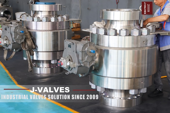
Large Diameter Ball Valves: Four Limits That Change The Design
Above a certain size a ball valve stops being a scaled one. Ball weight, operator torque, body split and the test bench each set a limit at a different size.
Read More
Cast Or Forged Ball Valve Body, And What A Radiography Acceptance Level Actually Buys You
Casting or forging is only half the decision. What RT, UT, MT and a proof test each find in a ball valve body, and where the geometry defeats all of them.
Read More