

CHINA J-VALVES Offers Various High-quality I ndustrial Ball Valves
J-VALVES, a distinguished professional ball valve manufacturer rooted in China, takes pride in its extensive product portfolio. Our offerings span a wide range, including trunnion-mounted ball valves, floating ball valves, high-temperature ball valves, high-pressure ball valves, metal-sealed ball valves, ultra-low temperature ball valves, DBB ball valves, Three-way And Four-way Ball Valve, and fully welded ball valves. Each product is a testament to our commitment to precision engineering and reliable performance. Meticulously crafted, they are designed to not only meet but exceed the most stringent industrial demands, ensuring stable operation even under extreme conditions. This enables us to provide our clients with high-value services and makes our valves widely sought-after in industries.
Product Category
Contact Us


-
J-VALVES-Q47F
-
J-VALVES
Overview of the J-VALVES stainless steel reduced bore trunnion valve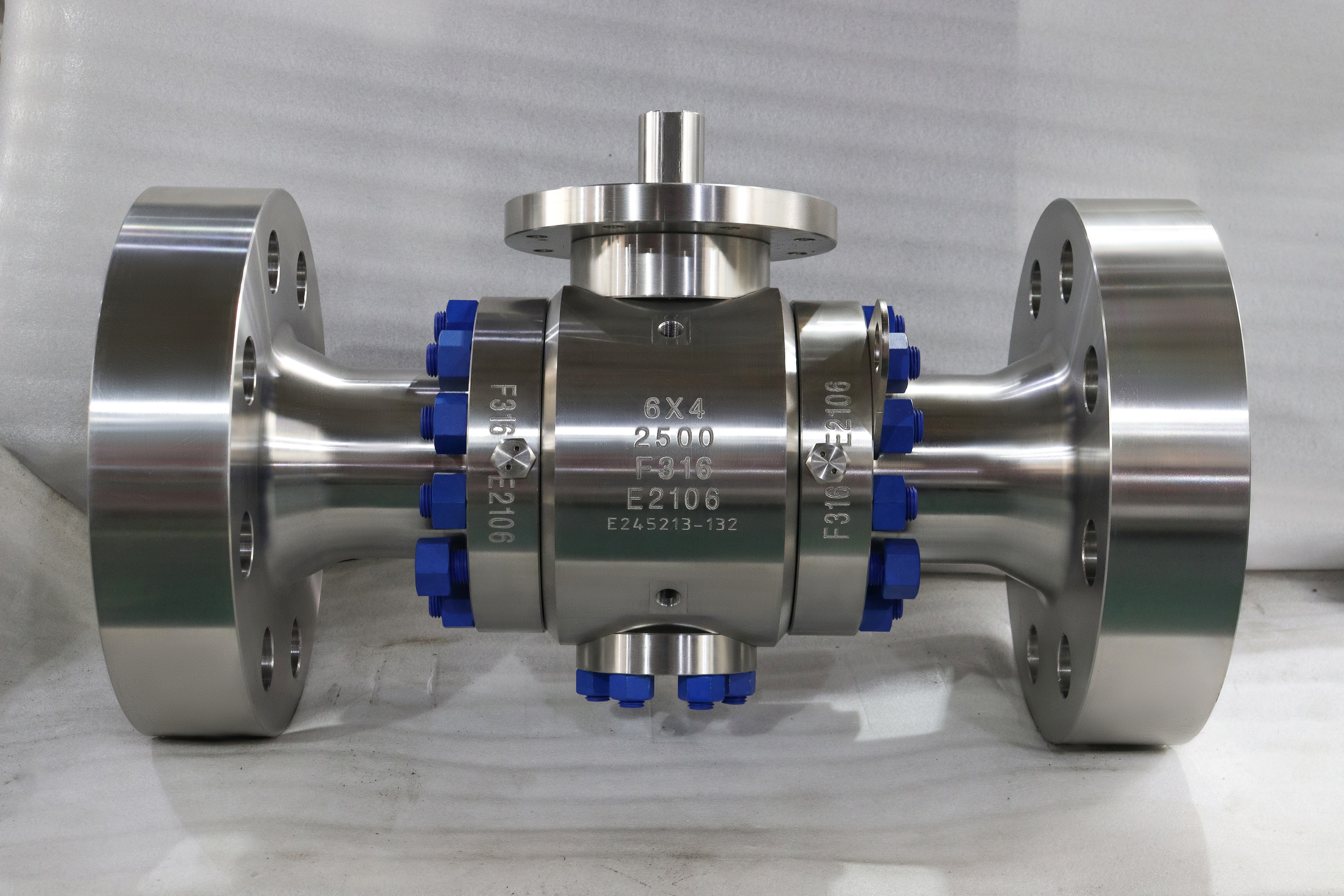
Close a ball valve with liquid on both sides and something has been created that did not exist before: a sealed volume of incompressible fluid. Nothing happens while the temperature is steady. Then the sun comes up, or the trace heating comes on, or the upstream line is depressurised and the downstream line is not, and that sealed volume tries to expand with nowhere to go.
The family runs from two inch to fifty six inch, Class 150 to Class 2500, in 304, 316 or 316L stainless, with the seat in PTFE, reinforced PTFE or metal and the ends flanged or butt welded. The photograph on this page is the six by four inch Class 2500 build, where the reduced bore is deliberate and where the cavity question is at its sharpest.
The argument here is that cavity pressure is set by temperature rather than by line pressure, and that a reduced bore valve makes it worse rather than better. The smaller ball leaves a smaller cavity, and a smaller cavity takes a larger share of the expansion from the same temperature rise. The space that reduced bore saves is a cost saving in the drawing and a pressure problem in a liquid line.
Design and Construction
The body is a three piece trunnion design with the ball carried on upper and lower trunnions and a spring loaded seat on each side. Between the two seats, around the ball, there is a cavity that is connected to the line only through the seats, and once the valve is closed that cavity is isolated from both ends.
Six by four means six inch ends and a four inch bore through the ball. The valve is dimensioned, flanged and tested as a six inch Class 2500 valve, and the reduction inside it lowers the torque and the ball weight. On a Class 2500 body that is a substantial saving, and it is the usual reason the notation appears at the top of the pressure range.
The seat is the component that decides what happens to the cavity, and there are two designs. A single piston effect seat is pushed onto the ball by line pressure from one side and by its spring from the other, and when the cavity pressure exceeds the line pressure the seat is pushed away from the ball and the cavity relieves into the line. A double piston effect seat is pushed onto the ball by pressure from either side, so the cavity is sealed from both directions and does not relieve at all.
That difference is invisible from outside the valve and it is the whole of the safety question on a liquid line. Two valves that look identical, weigh the same and carry the same nameplate will behave in opposite ways when a sealed cavity of liquid warms up.
The pressure in a sealed cavity is a function of temperature, not of the line pressure, and the reason is that liquids are almost incompressible. A small increase in temperature produces a small increase in volume, and because the liquid cannot compress, that increase has to be accommodated by the cavity expanding or by the pressure rising. The cavity is steel, so it does not expand much, and the pressure rises sharply.
| Situation | What Happens | What It Needs |
|---|---|---|
| Gas in the cavity | Compresses, pressure stays near line | Any seat design works |
| Liquid, steady temperature | No change after closure | Nothing |
| Liquid, warming up | Pressure rises with temperature | Self relieving or a bleed |
| Liquid, upstream released | Full differential across one seat | Double piston effect helps |
| Liquid, DPE seats and no bleed | Pressure has nowhere to go | A bleed, or SPE seats |
| Liquid, small cavity | Rises faster for the same rise | The same, sooner |
The small cavity row is the one that connects this page to the reduced bore design. The expansion is a proportion of the trapped volume, and the pressure rise depends on how much of that expansion the cavity can absorb before the steel resists. A cavity that is half the size reaches the same pressure with roughly half the temperature rise, other things being equal, which is why a reduced bore valve in liquid service deserves more attention than a full bore one rather than less.
The geometry of the cavity also changes where the liquid sits. In a valve installed with the stem up, the cavity is a ring around the ball with a high point and a low point, and whether it drains when the valve is opened depends on which way the valve is oriented. A cavity that holds liquid after the line is drained is a cavity that will be full when the line is put back into service.

Material Options
The stainless body is 304, 316 or 316L, and on a high class valve the choice is about corrosion rather than strength. The L grade has a lower carbon content, which makes it more resistant to sensitisation at weld heat input and slightly lower in allowable stress, so it sits in a lower material group in ASME B16.34 and has a lower rating at every temperature.
The seat is where the cavity behaviour is set, and it is also where the temperature limit is set. A reinforced PTFE insert gives tight shut off to about two hundred Celsius, and a PEEK insert or a metal seat takes the valve beyond that at the cost of a leakage rate. On a cavity-relief question the seat design matters twice, because the same seat that holds the pressure is the seat that decides whether the cavity can let go.
The body gasket has to survive the same temperature as the seat and it is often the part that limits the class at temperature. A spiral wound gasket with a graphite filler covers the whole range on this page, and a PTFE filled gasket does not. That choice is made when the valve is built and cannot be changed by the maintenance crew.
Technical Specifications
| Item | Value |
|---|---|
| Size range | Two inch to fifty six inch, DN 50 to DN 1400 |
| Build shown | Six by four inch, Class 2500, F316 |
| Pressure class | Class 150 to Class 2500, PN 20 to PN 420 |
| Construction | Three piece body, trunnion mounted ball |
| Body grades | 304, 316, 316L stainless |
| Seat | PTFE, reinforced PTFE, metal, SPE or DPE |
| Cavity | Sealed by the seats, relieving or not as specified |
| Ends | Raised face flange or butt weld |
| Face to face | The end size dimension, per ASME B16.10 |
| Temperature | Minus 46 to plus 200 Celsius, seat dependent |
| Test | API 598 shell and seat |
The seat row is the one to write out in full on an order. Single piston effect and double piston effect are two different articles with the same body and the same nameplate, and the difference only shows up in a cavity that has been sealed with liquid in it. A purchase order that says stainless trunnion ball valve and nothing else will receive whichever one the works builds by default.
Standards and Compliance
| Requirement | Document | What It Means Here |
|---|---|---|
| Product requirements | API 6D | Design, materials, marking, testing |
| Wall and rating | ASME B16.34 | Group 2.2 for 316, 2.3 for 316L |
| Pressure test | API 598 | Shell at 1.5 times, seat at 1.1 times |
| Fire test | API 607 or ISO 10497 | Type test, scope stated |
| Material certificate | EN 10204 3.1 | Heat number per pressure part |
| Cavity relief | Specified on the order | Not a default in the standards |
The cavity row is deliberate. The standards require a valve to hold pressure and to be testable; they do not decide for the buyer whether the seats should relieve. That is a design decision taken from the service, and the only place it can be recorded is the order and the drawing. A buyer who assumes the valve will look after itself in a liquid line has made a decision by default.
That gap between what a standard covers and what a service needs is where most cavity incidents come from. A valve that has passed every test on the bench and carries a full certificate can still be the wrong article for a blocked in liquid line, and no amount of documentation will show it, because the documents are all about the valve being built correctly rather than about it being specified correctly.
Manufacturing Process
The body is forged or cast, machined, pickled and passivated, and on a reduced bore design the bore through the ball is smaller than the end bore, with a machined transition between them. That transition is a step, and on a high class valve it is also a stress concentration, which is why it is radiused and why the radius is on the drawing.
The seat rings are machined to take the insert or the hardfacing, and the spring that loads each seat is calibrated so that the seat closes at low differential and opens at the design point. On a self relieving seat that spring rate is what sets the relieving pressure, so a spring that has been replaced with one of the wrong rate changes the behaviour of the valve.
Assembly follows a sequence: seats and springs, ball, trunnions, then the end pieces or the bonnet. The cavity is left accessible for the pressure test, and on a build with a cavity connection the connection is fitted before the test so that the cavity can be pressurised as part of it.

Quality Control and Testing
| Step | Check | Acceptance |
|---|---|---|
| 1 Incoming | Heat number against the mill certificate | Chemistry and mechanicals |
| 2 Identity | Positive material identification on body and trim | Grade match, L grade included |
| 3 Seat | Spring rate and seat type against the order | SPE or DPE as specified |
| 4 Shell test | Body and joints at 1.5 times | API 598, no leakage |
| 5 Seat test | Each seat at 1.1 times, direction by direction | API 598 rate |
| 6 Cavity test | Cavity pressurised, seats checked in reverse | Relief or seal, as designed |
| 7 Function | Cycles and torque recorded | Works limit |
| 8 Final | Cavity drained, ends capped, marked | Works standard |
The cavity test is the one that separates the two seat designs on the bench. Pressurise the cavity through the bleed, with both ends open, and a self relieving seat will pass at its relieving differential while a double piston effect seat will hold. That is a test of the design rather than of the workmanship, and it is worth witnessing once so that the difference is understood before the valve goes into a line where it cannot be seen.

Applications and Industry Service
This valve belongs on liquid service at high pressure where the line will be isolated with liquid in it: water injection, hydraulic systems, liquid product transfer, and the liquid filled sections of process units that are blocked in and left for long periods. In those duties the cavity is the design question and the bore is secondary.
It also belongs on gas service, where the cavity question largely disappears because gas compresses. A double piston effect seat on a gas line is a legitimate choice and is often preferred, because it gives two barriers in both directions and the cavity cannot build pressure from thermal expansion.
It is the wrong valve where a liquid line is blocked in, left in the sun, and fitted with double piston effect seats and no bleed. That combination is not a manufacturing defect and it is not a standards violation; it is a specification that left the cavity with nowhere to go, and it will damage the seats or the body before anyone notices.
Installation, Operation and Maintenance
Orient the valve so that the cavity connection, where one is fitted, is at the low point on a liquid line and at the high point on a gas line. That single installation decision decides whether the cavity can be vented and drained at all, and it costs nothing at the design stage and a great deal afterwards.
Operate the valve fully open or fully closed, and when a liquid line is blocked in, open a bleed before the line warms up rather than after. On a valve with a cavity connection the routine is simple: close, bleed, confirm the cavity is empty, and leave the bleed closed. On a valve without one, the only protection is the seat design, which is why the seat design has to be right at the order stage.
For maintenance the line is isolated, vented and drained, the body is opened, and the seats and ball come out. The springs are checked for free length and replaced if they have taken a set, because a spring that has relaxed changes the relieving point of a self relieving seat. The seat inserts are replaced as a pair, the gasket is renewed, and the cavity is cleaned before the body is closed.
How to Specify and Order
Six lines fix the article: the two sizes, class, body grade, the seat arrangement, the ends and the operator. On a liquid duty there is a seventh that matters more than any of them, which is the cavity arrangement: self relieving seats, or double piston effect seats with a bleed connection.
Three questions belong to the line rather than to the valve: is the medium liquid or gas, will the valve be blocked in with pressure on both sides, and can the cavity be vented. The first decides whether cavity pressure is a problem at all, the second decides how often, and the third decides whether the seats have to relieve because nothing else will.
Documents to name in the order: the EN 10204 3.1 certificate for each pressure part with its heat number, the seat type and spring specification, the shell and seat test record with a result per seat and per direction, the cavity test record, and the general arrangement drawing showing the cavity connection where one is fitted.
FAQ
Q: Why does cavity pressure rise in a liquid line?
A: Because the liquid is trapped and almost incompressible. A rise in temperature expands it slightly, the cavity is steel and does not expand with it, and the pressure has to take up the difference. Gas in the same cavity compresses instead, which is why the same valve behaves differently on a gas line.
Q: What is the difference between single and double piston effect?
A: A single effect seat is pushed onto the ball from one side and pushed off it by cavity pressure, so the cavity relieves into the line. A double effect seat is pushed onto the ball from both sides, so the cavity is sealed in both directions and cannot relieve. The two look identical from outside and are the same size and weight.
Q: Why is a smaller cavity worse?
A: Because the expansion is a share of the trapped volume. A cavity half the size takes roughly half the temperature rise to reach the same pressure, other things being equal. Reduced bore leaves a smaller cavity around a smaller ball, so it is the design that needs the most attention on a liquid line rather than the least.
Q: Does the standard require the seats to relieve?
A: No. The standards require the valve to hold pressure and to be testable. Whether the seats should relieve is a design decision taken from the service, and the only places it can be recorded are the order and the drawing. A buyer who assumes the valve looks after itself has made that decision by default.
Q: Where should the cavity connection be fitted?
A: At the low point on a liquid line and at the high point on a gas line, so that the cavity can be drained or vented. That is an installation decision and it costs nothing at the design stage, but a cavity that holds liquid after the line is drained will be full when the line comes back into service.



Hot Products


News
Why A Ball Valve Gets Harder To Turn: Five Causes, And The Test That Tells Them Apart
A ball valve that stiffens over months points at one of five parts. Measure torque with the line pressurised and again vented, and the split becomes visible.
Read More
The Ball Valve at Four Thousand Bar: Seat Load, Erosion And Fatigue in Waterjet Circuits
At 4,000 bar a 10 mm bore puts 31 kN on the seat and a 0.1 mm leak cuts steel. What a ball valve must survive in a waterjet or intensifier circuit.
Read More
Large Diameter Ball Valves: Four Limits That Change The Design
Above a certain size a ball valve stops being a scaled one. Ball weight, operator torque, body split and the test bench each set a limit at a different size.
Read More
Cast Or Forged Ball Valve Body, And What A Radiography Acceptance Level Actually Buys You
Casting or forging is only half the decision. What RT, UT, MT and a proof test each find in a ball valve body, and where the geometry defeats all of them.
Read More