

CHINA J-VALVES Offers Various High-quality I ndustrial Ball Valves
J-VALVES, a distinguished professional ball valve manufacturer rooted in China, takes pride in its extensive product portfolio. Our offerings span a wide range, including trunnion-mounted ball valves, floating ball valves, high-temperature ball valves, high-pressure ball valves, metal-sealed ball valves, ultra-low temperature ball valves, DBB ball valves, Three-way And Four-way Ball Valve, and fully welded ball valves. Each product is a testament to our commitment to precision engineering and reliable performance. Meticulously crafted, they are designed to not only meet but exceed the most stringent industrial demands, ensuring stable operation even under extreme conditions. This enables us to provide our clients with high-value services and makes our valves widely sought-after in industries.
Product Category
Contact Us

-
J-VALVES-Q347F
-
J-VALVES
Overview of the J-VALVES 8 inch Class 2500 F11 trunnion ball valve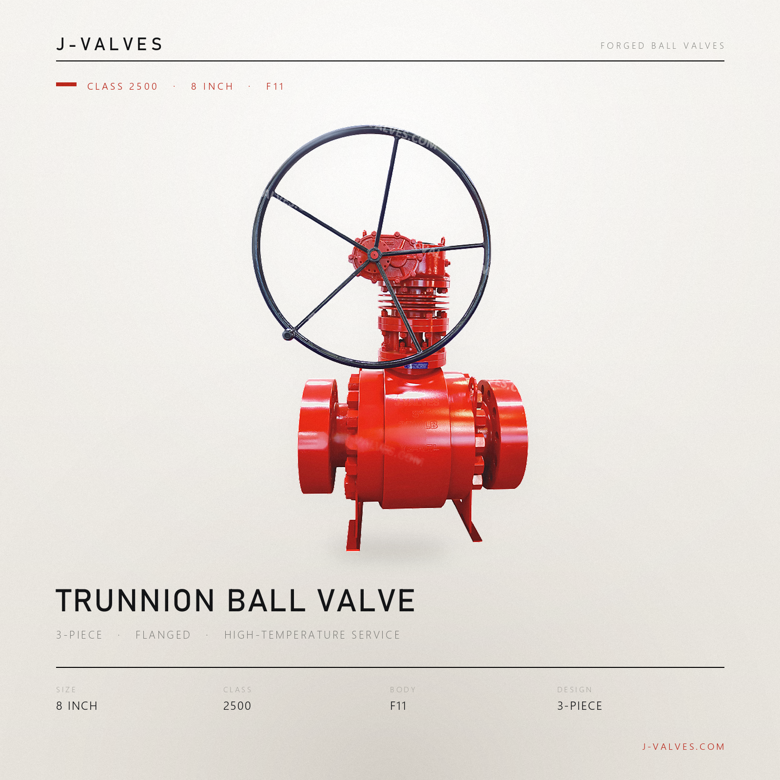
The heading says F11, and on this valve the F11 is not only the body. The ball is F11, the seats are F11, and the only parts that are not are the hardfacing on the two sealing surfaces, the stem and the bolting. That decision, repeated three times down a material list, is what makes an eight inch Class 2500 metal seated valve behave predictably when it is cycled between ambient and the top of its range.
It is worth saying why the repetition matters, because it looks like laziness on a data sheet and it is not. When the body and the trim are different steels, the gap between ball and seat changes with temperature by the difference between two expansion rates. That difference does not stay constant as the valve heats: it grows, and on some material pairs it changes sign, so a valve that was set with preload at ambient is either loose or tight at temperature. With one steel in all three parts the growth is proportional, the seat spring absorbs it, and the setting made at assembly is still roughly the setting in service.
The valve itself is eight inch, DN 200, at Class 2500, which API 6D clause 7.2 records as PN 420. The ends are ring type joint flanges to ASME B16.5, the port is full, the body is forged A182 F11 in the normalized and tempered condition, and the operator is a gear. The stamped range on the plate is minus 29 to plus 425 C.
Design and Construction
The body is three forgings: a centre piece that carries the ball, the trunnion bearings and the stem, and two end pieces that carry the ring joint flanges. Each end piece closes on its own ring of studs with its own ring gasket, so the valve has two pressure joints rather than the one a two piece body would have. At this class the choice is deliberate, because a forging of this size is easier to make in three pieces than in two, and each piece can be proved separately before assembly.
The ball does not float. It is held between an upper and a lower shaft, and those shafts run in bearings that take the thrust the pressure puts on the ball. The ball therefore stays on the centreline of the bore no matter what the pressure is, and the two seats are the parts that move. That is the whole reason a trunnion valve can be turned by hand at a class where a floating ball of the same size would need a bar on the lever.
Each seat is a ring in a pocket with a spring behind it, and the ring face that touches the ball carries the hardfacing. On this valve the seat is a single piston effect pattern, which means line pressure from the upstream side pushes the seat towards the ball and line pressure from the downstream side pulls it away. The spring supplies the preload that makes the valve tight when there is no pressure at all, which is the condition it is in when the line is drained for maintenance and someone checks it by hand.
Each joint is a ring joint: a groove in each flange face, an octagonal or oval metal ring in the two grooves, and metal against metal when the studs are tensioned. There is no soft gasket to relax, which is why it is used at this class, and why the groove has to be cut to the ring standard rather than to a note that says ring joint.
The stem enters through the centre piece and is retained by a shoulder from the inside, so pressure cannot push it out. Above it sits a gland that compresses graphite packing, and on this valve the gland is live loaded, which means springs or disc washers keep pushing on the packing as it compresses. Graphite does not melt at these temperatures, but it does compact and lose thickness, and without the live load the gland bolts would need retorquing after every thermal cycle.

Material Options
A182 F11 is a 1.25 percent chromium, 0.5 percent molybdenum forging, and it is specified in the normalized and tempered condition because that is the condition the standard requires for the grade rather than an optional extra. The chromium is there for oxidation resistance and the molybdenum for creep strength, and the pair is what allows a carbon steel body design to be used at temperatures where plain carbon steel would be losing strength.
| Component | Standard Build | Options | What It Decides |
|---|---|---|---|
| Body and end pieces | A182 F11 forged, normalized and tempered | F22 for higher temperature, F316 where the medium is corrosive | Creep life and oxidation limit |
| Ball | F11 with cobalt based hardfacing | F11 nitrided, or a nickel based overlay | Whether the seat pair survives thermal cycling |
| Seat | F11 with cobalt based hardfacing | Nickel based hardfacing for severe erosion | The sealing surface and its wear life |
| Stem | 17-4PH | Nickel based high temperature alloy | Stem strength at temperature |
| Packing | Flexible graphite, live loaded | Pure graphite with an anti-extrusion ring | Stem seal after thermal cycling |
| Ring gasket | Soft iron, octagonal or oval | 304 or 316 ring for corrosive service | The metal to metal joint at each end |
| Bolting | A193 B16 with A194 grade 7 nuts | Nickel based studs for the top of the range | Whether the joint stays tight when hot |
| Bearings | Nickel based with solid lubricant | Graphite bushings | Torque after a heat soak |
The bolting row is the one that gets overlooked. A193 B7 is the default on carbon steel valves and it is a chromium molybdenum steel that loses preload at temperature through relaxation, which on a ring joint joint means the seal is lost rather than loosened. B16 is the chromium molybdenum vanadium grade intended for this duty, and it is normally paired with A194 grade 7 nuts rather than 2H.
The ring gasket is a consumable and should be ordered as one. Soft iron rings are the standard for a clean, dry, non corrosive service and they deform into the groove on first make up, which means they are not reusable. Stainless rings are used where the medium would attack iron, and they are harder, so the groove has to be in good condition or the ring will not bed.
Technical Specifications
Class 2500 is the top of the flanged range in ASME B16.34, and at eight inch it is a heavy casting sized item rather than a catalogue part. The cold rating is 6000 psi for this group, and the shell test at 1.5 times that figure is the number that decides the wall and the joint, not the line pressure the valve will see.
| Item | Value |
|---|---|
| Size | Eight inch, DN 200 |
| Pressure class | Class 2500, recorded as PN 420 in API 6D clause 7.2 |
| Body style | Three piece forged body, trunnion mounted ball, full port |
| Body material | A182 F11, 1.25Cr-0.5Mo, normalized and tempered |
| Cold rating | 6000 psi at 38 C |
| Flange | ASME B16.5 Class 2500, ring type joint |
| Ring gasket | ASME B16.20, octagonal or oval |
| Face to face | ASME B16.10 for NPS 8 Class 2500, confirmed on the signed drawing |
| Seat | Metal to metal, single piston effect, spring preloaded |
| Packing | Flexible graphite, live loaded |
| Bolting | A193 B16 with A194 grade 7 |
| Temperature | Minus 29 to plus 425 C as stamped |
| Operator | Gear as photographed, actuator per order |
| Test | API 598 shell and seat, seat proved each side with the cavity vented |
The stamped range deserves a note, because the page it came from contradicts itself. The parameter block says minus 29 to plus 425 C, and the description then claims service above 540 C in the same breath. Both cannot be true of the same valve, and the stamped range is the one that governs, so the page has been written to 425 C and the higher figure has been left out rather than repeated.
Face to face is tabulated by size and class in ASME B16.10 and it is the dimension the pipe spool is built to. On a valve of this size it should be taken from the signed general arrangement drawing rather than from a table, because the tabulated figure is a minimum and a forging plus its end pieces can come out longer.
Standards and Compliance
Three documents do the work on this valve and they are often quoted as if they were one. ASME B16.34 gives the wall thickness and the pressure temperature rating for the material group. API 6D gives the product requirements, the marking and the test. API 598 gives the test procedure. A quotation that names only the product standard is telling you the valve was designed to something, not that it was proved to anything.
| Requirement | Document | What It Means Here |
|---|---|---|
| Wall and rating | ASME B16.34, chrome moly group | 6000 psi at 38 C, falling with temperature |
| Flange and groove | ASME B16.5 Class 2500 | Ring joint facing, eight inch bolt circle |
| Ring gasket | ASME B16.20 | Octagonal or oval, matched to the groove |
| Face to face | ASME B16.10 | The dimension the spool is built to |
| Product requirements | API 6D | Design, marking, documentation |
| Pressure test | API 598 | Shell 1.5 times, seat 1.1 times |
| Fire test | API 607 or ISO 10497 | Type test, scope to be read |
| Material certificate | EN 10204 3.1 | Heat number matched to the part |
API 608 does not belong on this page and it appears on the source because the template carries it. That standard covers valves from DN 15 to DN 600 in Class 150 to Class 600, and a Class 2500 valve is outside it by class rather than by quality. Naming it on a 2500 class quotation is a small thing that tells a careful buyer the document set was assembled from a template.
The fire test claim needs the same care. A metal seated valve is fire safe in the sense that there is no soft seat to burn, but a certificate is still a type test on a specimen and its scope says which size and which class were tested. A valve this size is unlikely to be inside a certificate issued for small sizes, and the certificate number should be read for scope before it is put in a project file.
Manufacturing Process
The three forgings are machined in separate settings and then brought together on the centre piece, so the operation that matters is the one that cuts the seat pocket and the ring joint groove in the same reference. If the groove and the pocket are cut from different datums, the two end pieces will close on the ball at slightly different heights, and the seats will carry unevenly for the rest of the valve's life.
The ball is machined, hardened and then ground, and on a metal seated valve the spherical surface is a sealing surface rather than a flow surface, so it is finished to a sphericity the seat can conform to. The hardfacing is deposited before the final machining, then finished, and a cobalt based overlay is the usual choice because it keeps its hardness at temperature and resists galling against a similar surface. The seat ring is then lapped against the ball it will run with, and the pair is kept together from that point. A replacement seat supplied without its ball is a part that has to be lapped again on site, which is not a workshop operation.
Assembly is the centre piece first, with the ball on its trunnion and the stem in place, then the seats and their springs, then the two end pieces on their studs in a cross pattern to the drawing figure. The gearbox goes on last and the stops are set so the ball is fully open and fully closed at the ends of travel, because a stop set a few degrees short leaves a crescent of seat exposed to the flow.

Quality Control and Testing
The heat number is stamped on each forging and repeated on the certificate, and on a chrome moly valve it is checked as much for grade as for identity, because F11 and F22 look the same and behave differently at temperature. A portable analyser will separate them on chromium and molybdenum, and it will not tell you the heat treatment condition, which is why the certificate is the primary document and the analyser is the cross check.
| Step | Check | Acceptance |
|---|---|---|
| 1 Incoming | Heat number against the mill certificate | A182 F11 chemistry, normalized and tempered |
| 2 Identity | Positive material identification on each forging | Chrome moly grade match |
| 3 Hardness | Body and hardfacing hardness after heat treatment | Drawing figure, recorded per part |
| 4 Machining | Seat pocket to ring groove reference | Drawing tolerance |
| 5 Lapping | Seat lapped against its own ball | Contact band per works standard |
| 6 Shell test | Body and both joints at 1.5 times | API 598, no leakage |
| 7 Seat test | Each seat at 1.1 times, cavity vented | API 598 rate for a metal seat |
| 8 Final | Grooves greased, faces masked, marked, crated | Works standard |
The seat test is where a metal seated valve separates from a soft seated one. API 598 accepts a metal seat at a leakage rate rather than at zero, and a buyer who expects zero should hear that before the order. The record should show two results, one per seat, because with the cavity vented only the seat facing the pressure is loaded.
The shell test at this class is a serious operation and the joint is what is being proved, not the forging. A ring joint that has been assembled with a damaged groove will pass a dimensional check and fail at 1.5 times, and it will fail at the groove rather than at the ring, which is why the grooves are inspected and photographed before the end pieces go on.

Applications and Industry Service
Chrome moly trunnion valves at this size and class belong to the parts of a plant where the temperature is the problem rather than the pressure. Hydrotreating and hydrocracking circuits, coker fractionation, high temperature steam and hot hydrocarbon rundown all use F11 or F22 bodies because the alternative is a stainless steel that costs more and conducts heat less well.
The reason F11 rather than F22 in most of those duties is economics rather than metallurgy. F22 holds strength to a higher temperature, and it is bought when the design temperature is high enough that F11's creep life becomes the limit. Below that point F11 is the cheaper way to get the same rating, and the two grades are dimensionally interchangeable in the same body pattern.
The valve is a poor choice in two situations. The first is a medium that attacks chromium steels, where the body grade has to change to stainless and the whole thermal argument changes with it. The second is a line that will be cycled often, because a metal seat with hardfacing on both sides wears at the contact band and the wear shows up as a rising leakage rate rather than as a failure.
The eight inch size is the one where the gearbox stops being optional. Above roughly this size the torque needed to turn a ball against two loaded metal seats is beyond a lever, and the gear ratio also gives the operator the mechanical advantage to seat the valve fully rather than nearly.
Installation, Operation and Maintenance
The valve can be installed either way round, because the seat arrangement seals against pressure from either side. What does not travel is the cavity connection, and on a valve with a drain or a bleed fitted it should end up where it can be reached and where it will drain, which on a horizontal line means the bottom.
Bring the mating flanges up parallel and check the ring grooves before the gasket goes in. A ring joint will not forgive an angular misalignment the way a sheet gasket does, because the ring has to sit in both grooves at once, and a flange pulled square by the studs puts a bending load into the end piece that shows up as a groove crack years later.
The first heat up is the operation that tells you whether the packing was set correctly. Bring the line up slowly, check the gland after it has been at temperature for a few hours, and record what the live load did. On a valve with graphite packing and a live loaded gland nothing should need retorquing, and if something does, the live load was not sized for the packing it was given.
For maintenance the line is isolated, drained and vented through the cavity connection, the end piece studs are released in a pattern, and the end piece comes away with its seat and its ring. The seat and ball are a lapped pair, so a seat is replaced with a ball or relapped against the ball that is in the valve, and the ring gasket is replaced rather than reused.
How to Specify and Order
Six lines fix the valve: size, class, body grade, seat type, flange facing and operator. On a chrome moly valve at this class there are three more that belong on the order and are routinely left off: the heat treatment condition of the forgings, the bolting grade, and whether the ring gaskets are supplied with the valve or by the pipe contractor.
Four questions belong to the line rather than to the valve: the design temperature, the design pressure, the medium, and the number of thermal cycles expected over the life of the plant. The temperature decides whether F11 is enough and whether the packing is graphite; the pressure confirms the class; the medium decides the body grade and the ring material; the cycle count decides whether a metal seat is the right wear part at all.
Documents to name in the order: the EN 10204 3.1 certificate for each forging with the heat number matched to the part, the heat treatment record, the shell and seat test record with two seat results, the ring gasket certificate if the gaskets are supplied, and the general arrangement drawing carrying the face to face dimension the spool will be built to.
FAQ
Q: Why are the ball and seats the same steel as the body?
A: So that the trim grows at the same rate as the shell. When the body and the trim are different steels the gap between ball and seat changes with temperature by the difference between two expansion rates, and a valve set with preload at ambient is loose or tight when it is hot. One steel in all three parts makes the growth proportional and lets the seat spring absorb it.
Q: Does a metal seated valve at this class leak at zero?
A: No. API 598 accepts a metal seat at a leakage rate that scales with the nominal size, not at zero. A buyer who needs zero leakage is asking for a soft seat, and a soft seat is not available at the top of this temperature range. The rate belongs in the purchase order so that it is agreed before the witness test.
Q: Why a ring joint rather than a raised face flange?
A: Because a ring joint is metal against metal with no soft gasket to relax. At Class 2500 and at temperature, a sheet or spiral wound gasket creeps and the joint loses preload. The ring joint does not, and the price is that the groove has to be cut to the ring standard and the ring is not reusable.
Q: What does the N in A105N mean, and does F11 have an equivalent?
A: The N in A105N is a heat treatment state, not a different chemistry: it means the forging was normalized. F11 is required in the normalized and tempered condition by its own specification, so there is no separate N suffix to add. In both cases the heat treatment record is part of the material documentation.
Q: The page says service above 540 C and also 425 C. Which is right?
A: The stamped range is 425 C and that is the figure that governs. The higher figure appears in the description of the source page and contradicts the parameter block on the same page. It has been left out of this version rather than repeated, and the corrected range should be confirmed in writing before the page goes live.


Hot Products


News
Why A Ball Valve Gets Harder To Turn: Five Causes, And The Test That Tells Them Apart
A ball valve that stiffens over months points at one of five parts. Measure torque with the line pressurised and again vented, and the split becomes visible.
Read More
The Ball Valve at Four Thousand Bar: Seat Load, Erosion And Fatigue in Waterjet Circuits
At 4,000 bar a 10 mm bore puts 31 kN on the seat and a 0.1 mm leak cuts steel. What a ball valve must survive in a waterjet or intensifier circuit.
Read More
Large Diameter Ball Valves: Four Limits That Change The Design
Above a certain size a ball valve stops being a scaled one. Ball weight, operator torque, body split and the test bench each set a limit at a different size.
Read More
Cast Or Forged Ball Valve Body, And What A Radiography Acceptance Level Actually Buys You
Casting or forging is only half the decision. What RT, UT, MT and a proof test each find in a ball valve body, and where the geometry defeats all of them.
Read More