

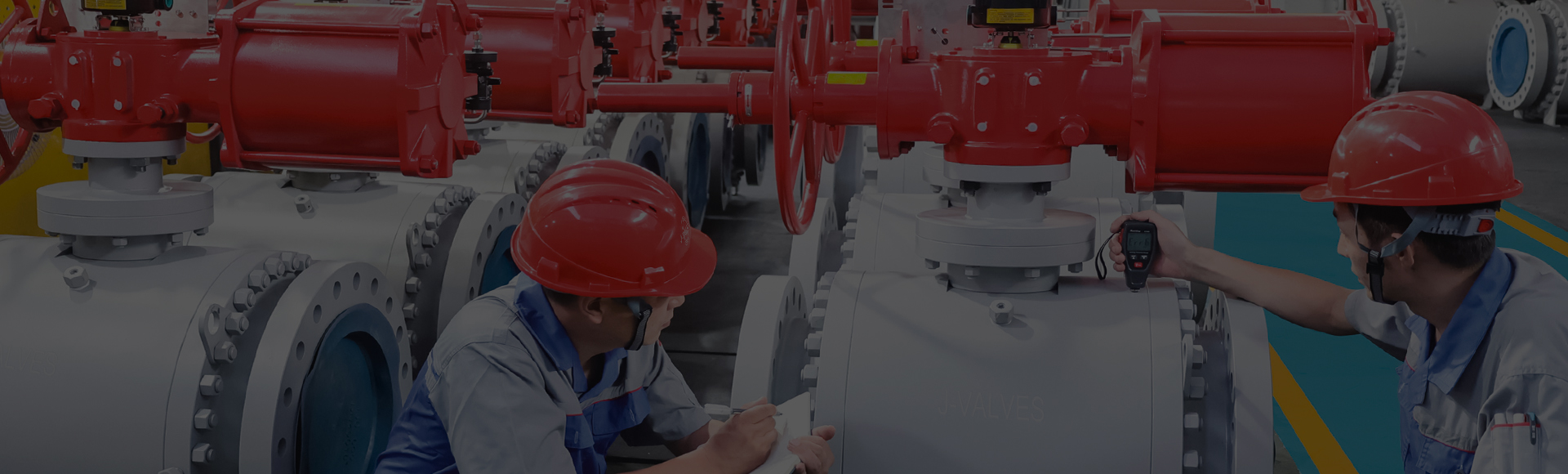
CHINA J-VALVES Offers Various High-quality I ndustrial Ball Valves
J-VALVES, a distinguished professional ball valve manufacturer rooted in China, takes pride in its extensive product portfolio. Our offerings span a wide range, including trunnion-mounted ball valves, floating ball valves, high-temperature ball valves, high-pressure ball valves, metal-sealed ball valves, ultra-low temperature ball valves, DBB ball valves, Three-way And Four-way Ball Valve, and fully welded ball valves. Each product is a testament to our commitment to precision engineering and reliable performance. Meticulously crafted, they are designed to not only meet but exceed the most stringent industrial demands, ensuring stable operation even under extreme conditions. This enables us to provide our clients with high-value services and makes our valves widely sought-after in industries.
Product Category
Contact Us


-
J-VALVES-Q347F
-
J-VALVES
Overview of the J-VALVES 14 inch 300LB WCB trunnion ball valve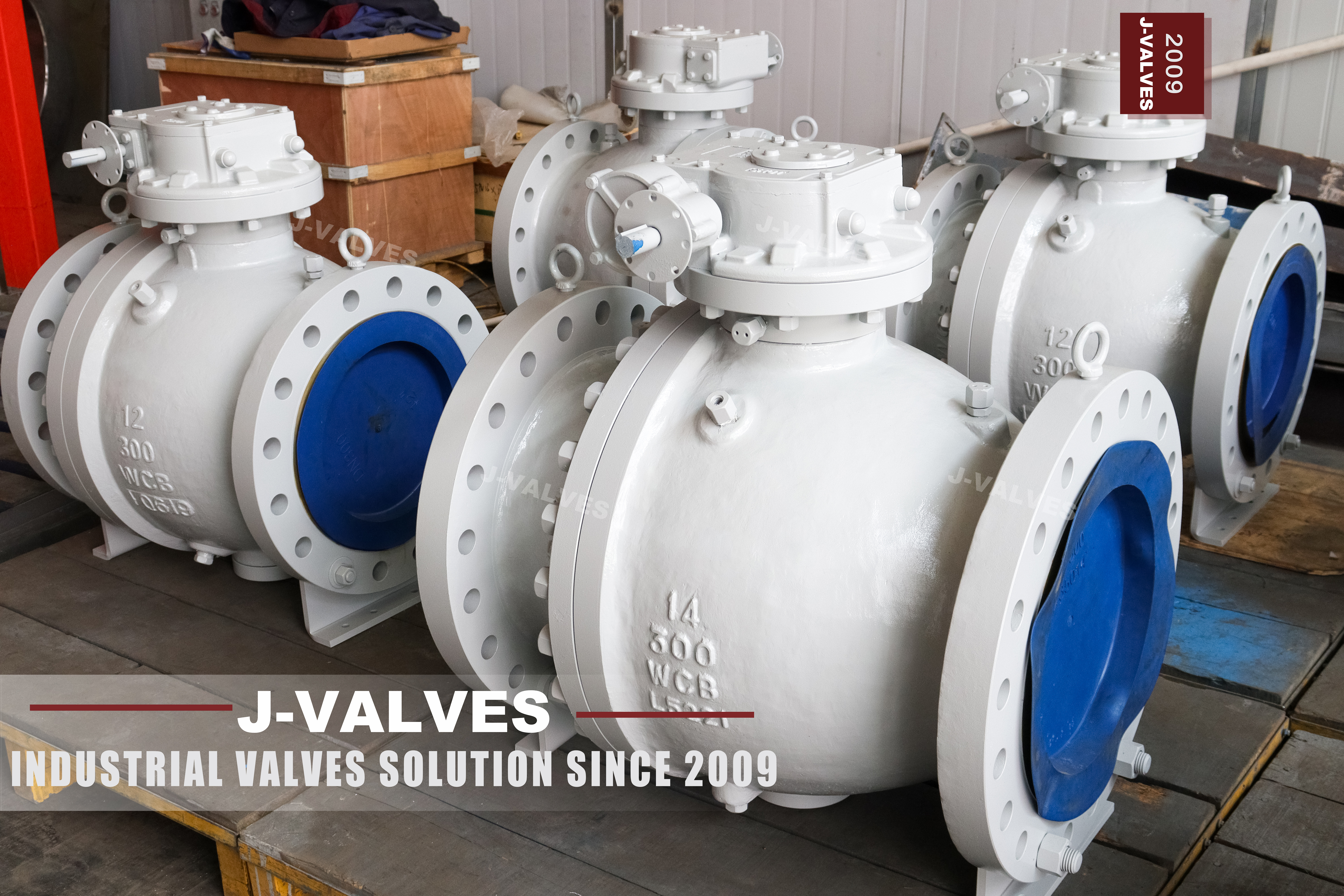
There is a size at which a valve stops being a fitting and becomes an item of plant, and fourteen inch at Class 300 is past it. A fitting is something two people lift and bolt in. This valve has lifting eyes screwed into its flange stud holes, two welded feet underneath, and a geared handwheel on top, and all three of those exist because the valve is too large to be handled, supported or operated by hand.
The class is modest. Class 300 in group 1.1 of ASME B16.34 reads 740 psi at 38 C, which is a water or utility pressure, and the wall that carries it is not the reason the body is heavy. The body is heavy because it has to be stiff enough to hold a fourteen inch ball in line, and because at this size the trunnion arrangement stops being an option and becomes the only way the valve can work at all.
The photographs show the whole argument. The eyes are in the flange holes, the feet are under the body, the gear is bolted on top with the handwheel beside it, and the bore is large enough to see the far flange through. The plate reads 14, 300, WCB and a heat code.
This page is about the parts of a large valve that are not in the flow path: how it is lifted, how it is supported, how it is turned, and why each of those is a specification item rather than a detail left to site.
Design and Construction
The body is two castings, a main body with one flange and the trunnion bearings, and a cap with the other flange and one seat. The joint between them is a full circle of studs and a gasket and it holds line pressure all the time the line is live. Fourteen inch is inside ASME B16.5, so the flanges are a standard pattern with a standard bolt circle.
The ball is carried on an upper and a lower trunnion. At this diameter a floating ball is not a cheaper alternative, it is not an alternative at all: the force that pressure puts on a ball scales with its area, and at fourteen inch the seat could not absorb it without deforming. The trunnion takes that force into bearings, the stem only turns the ball, and the seat is left with the much smaller job of sealing.
The gear is the third piece of the argument. A handwheel on a direct stem would need a force no operator should have to produce, so the gear multiplies it, and the position indicator on the housing tells the operator where the ball actually is. What the gear does not do is limit the torque: a geared valve can be forced past its stop by a determined arm.
Gear selection on a valve this size is not a free choice between a wheel and a lever. A lever of any sensible length cannot produce the force needed to seat a fourteen inch ball, so the gear is the mechanism that makes the valve operable at all, and the handwheel diameter is the visible consequence of that. Where the valve will be automated, the same pad takes an actuator and the gear is omitted.
Material Options
A216 WCB is the body grade, and at this size the casting route is the only economic one. The ball and seats can be built several ways, and the choice is driven by the medium rather than by the class, because a 300 lb valve is not being asked to survive pressure so much as to survive its contents.
Wall thickness at Class 300 is modest, and at fourteen inch the casting is therefore a shell rather than a pressure vessel in the ordinary sense. That is why the coating matters more than the wall: a body that is 740 psi rated and painted for a plant atmosphere will corrode from the outside long before it is stressed from the inside, particularly where water collects on the top of the shell.
The ball in a cast carbon body is usually WCB with a nickel or chrome coating, or a CF8 or CF8M stainless part where the bore has to stay clean. A stainless ball is the upgrade worth making at this size, because a ball of this diameter is a substantial part to replace and the coating is what fails first.
| Component | Standard Build | Options | What It Decides |
|---|---|---|---|
| Body and cap | ASTM A216 WCB | CF8 or CF8M cast stainless | Corrosion and low temperature limit |
| Ball | WCB with electroless nickel or hard chrome | CF8 or CF8M stainless | Bore life at a large diameter |
| Seat | PTFE, reinforced PTFE or PPL | Metal seat with hard facing | Temperature ceiling |
| Stem | 316 stainless | 17-4PH | Drive strength under a gear |
| Packing | Flexible graphite | Braided graphite with alloy wire | Stem seal at temperature |
| Body joint gasket | Spiral wound, graphite filled | Ring joint gasket | The single joint at full line pressure |
| Bolting | A193 B7 with A194 2H | B8M with 8M | Thermal match with the body |
| Lifting and support | Eyes in the flange holes, welded feet | Lifting lugs cast on the body | How the valve is handled and supported |
Technical Specifications
The valve is fourteen inch, Class 300, cast WCB, two piece body, trunnion mounted, gear operated, flanged to ASME B16.5. PN 50 is what API 6D calls this class, and the group 1.1 table in ASME B16.34 gives 740 psi at 38 C as the ceiling.
| Item | Value |
|---|---|
| Size | Fourteen inch, DN350 |
| Pressure class | Class 300, recorded as PN 50 in API 6D clause 7.2 |
| Body style | Two piece cast body, trunnion mounted ball |
| Body material | ASTM A216 WCB, ASME B16.34 group 1.1 |
| Rating | 740 psi at 38 C in group 1.1 |
| Flange | ASME B16.5 Class 300, raised face or ring joint |
| Bore | Full port as photographed |
| Face to face | ASME B16.10 for NPS 14 Class 300, confirmed on the signed drawing |
| Temperature | Minus 29 to plus 425 C as a body figure |
| Operator | Worm gear with handwheel as photographed |
| Lifting | Eyes in the flange stud holes; sling around the body |
| Support | Feet under the body, or pipe supports either side |
The dimension that matters most at this size is not on the data sheet: it is the clearance around the valve. Fourteen inch flanges are wide, the studs are long, and the gear and handwheel add height. A valve that fits the gap in the pipe can still be impossible to install because there is no room to swing a wrench on the far side.
The flange is the other dimensional trap. Fourteen inch at Class 300 is a wide flange with long studs, and the space needed to swing a wrench on the far side is often more than the space between the valve and the next fitting. Installation drawings that show the valve and not the wrench are the reason site work runs late.
Standards and Compliance
API 608 and API 6D both cover this valve, and both are worth citing because a fourteen inch Class 300 valve is inside the size and class scope of each. ASME B16.34 supplies the wall and the rating, and ASME B16.5 fixes the flange at a size that is still inside its table.
At this size the standards also govern how the valve is marked and how it is tested, and both are recorded per valve rather than per batch. A fourteen inch body is not made in a run of hundreds, so the test record is the only evidence that this particular valve was proved rather than its neighbours.
| Requirement | Document | What It Means Here |
|---|---|---|
| Wall thickness and rating | ASME B16.34 group 1.1 | 740 psi at 38 C in group 1.1 |
| Flange dimensions | ASME B16.5 Class 300 | Standard bolt circle at NPS 14 |
| Face to face | ASME B16.10 | Confirmed on the signed drawing |
| Product standard | API 608 and API 6D | Both apply at this size and class |
| Pressure testing | API 598 | Shell 1.5 times, seat 1.1 times |
| Fire test | API 607 or ISO 10497 | Type test with a scope on the certificate |
| Casting examination | Radiography or ultrasonic when ordered | Report with the certificate |
| Material certificate | EN 10204 3.1 | Heat number matched to the plate |
Manufacturing Process
Casting a fourteen inch body takes a mould large enough that the gating and feeding design is a project in itself. The thick flange sections have to be fed while the thinner shell solidifies, and the result is a body that is sound where it matters or not, with little room for correction afterwards. That is why an examination clause belongs on an order of this size.
Machining is done on a machine large enough to hold the body and turn the flange faces square to the bore. The joint face and the two flange faces are cut in relation to the same axis, so that the valve sits in the pipe without pulling the spool out of line. The seat pockets and the trunnion bores follow, and the body is then cleaned and painted.
The feet and the lifting points are part of the casting or are added before painting. Either way they are checked for position rather than for appearance, because a foot that does not reach the foundation is a foot that transfers nothing, and an eye that is in the wrong hole is a sling that pulls the valve over.

Quality Control and Testing
Testing a valve this size takes a test bench built for it, and the shell test is the moment when the single body joint and the stem seal are loaded together at one and a half times the rating. The seat test follows at one and one tenth, with the cavity vented so that the reading describes the seat.
| Step | Check | Acceptance |
|---|---|---|
| 1 Incoming | Heat number against the mill certificate | A216 WCB chemistry and tensile |
| 2 Casting | Radiography or ultrasonic when ordered | Report to the stated acceptance level |
| 3 Machining | Flange squareness, joint face flatness, bore | Drawing and ASME B16.5 |
| 4 Dimensional | Face to face, bolt circle, foot position | ASME B16.10 and the drawing |
| 5 Shell test | Body, joint and stem at 1.5 times | API 598, no leakage |
| 6 Seat test | Each seat at 1.1 times, cavity vented | API 598, zero visible on a soft seat |
| 7 Function | Gear travel, indicator, stop, effort by hand | Works standard |
| 8 Final | Cavity drained, bore dried, faces masked, coating | Works standard |
The function check includes turning the valve by hand on the gear, and that is not a formality. A valve that needs two people on the wheel in the works will need more on site, and the time to find that out is before the paint is dry.
The same check establishes whether the gear has been filled and adjusted at the works rather than at site, which on a valve this size is the difference between a commissioning task and a commissioning problem.

Applications and Industry Service
Fourteen inch Class 300 sits on water and utility headers, tank farm manifolds, cooling water systems, fire protection mains and plant distribution lines. The medium is usually liquid, the pressure is modest, and the valve is expected to isolate a large section of the plant when it is needed.
In those duties the supports matter as much as the valve. A fourteen inch spool full of water is heavy, and a valve hanging between two flanges with no support underneath will deflect, which puts the joint out of square and loads the studs unevenly. The feet on the body exist so that this does not happen.
Water hammer is the event a valve this size is judged by. A fourteen inch column of water stopped by a closing ball produces a pressure wave that travels back up the line, and the parts that see it are the body joint and the studs rather than the seat. Closing the valve slowly, by gear rather than by a snap, is the cheapest protection available.
Installation, Operation and Maintenance
Plan the lift before delivery. Use the eyes in the flange holes or a sling around the body, never the handwheel or the gear housing, and never a stud that has not been checked. Set the valve on its feet or on supports either side, and check that both flange faces are parallel to the pipe before any stud is tensioned.
Bring the joint up in a cross pattern in stages, with a new gasket, and leave the gear in the position it will be commissioned in. A valve that has been shipped closed and is installed closed will have its seat in contact with the ball for the whole of the installation, which is a small but real load on a soft seat.
Tensioning a large flange takes more than one pass. The studs are brought up to a fraction of the figure, then to the figure, then checked around the circle, because a stud tensioned once to full value will relax as its neighbours are tightened. On a joint this size the sequence takes time and skipping it is what produces a weep at the bottom of the ring.
For a seat change the line is isolated, drained and vented, the cavity is bled, and the cap studs are released in a pattern. The cap is heavy and needs a lift. The gasket is replaced, the seat clearance is checked, and the joint is re-torqued to the drawing figure before the valve is tested.
How to Specify and Order
Size, class, body grade, seat material, flange facing and the operator are the six lines that fix what arrives. For a valve this size three more belong on the order: the lifting arrangement, the support arrangement, and the spares package of gaskets and seats.
Four questions are about the line: the medium, the temperature, the pressure, and the space available around the valve. The medium decides the body and ball, the temperature decides the seat, the pressure confirms the class, and the space decides whether the valve can be installed at all.
Documents worth naming: EN 10204 3.1 with the heat number matched to the plate, the casting examination report if one was specified, the shell and seat test record, and the dimensional report. On a valve that will be in service for decades, the file is as much a part of the delivery as the valve.
FAQ
Q: Why does a fourteen inch valve have lifting eyes?
A: Because it cannot be handled by hand. The eyes in the photographs are screwed into two of the flange stud holes, which keeps the pressure boundary untouched and gives a rigger a certified thread to lift from. The gear housing and the handwheel are not lifting points.
Q: What are the feet under the body for?
A: To take the valve weight onto a foundation or a structural support instead of onto the two flanges. A body this size hanging between two flanges will deflect, which puts the joint out of square and loads the studs unevenly.
Q: Is a lever available at this size?
A: No. A lever of any sensible length cannot produce the force needed to seat a fourteen inch ball, so the gear is the mechanism that makes the valve operable at all. Where the valve is automated, the same pad takes an actuator and the gear is omitted.
Q: Why is the class only 300 on such a large valve?
A: Because the pressure in a large water or utility header is modest, and the body is sized by stiffness and flange geometry rather than by hoop stress. A fourteen inch Class 300 valve is heavy because it is big, not because it is holding a high pressure.
Q: Does the valve have to be supported during installation?
A: Yes, on its feet or on pipe supports either side. The flanges are not designed to carry the body weight plus a water filled spool, and a joint that has sagged leaks at the bottom of the ring where it is least visible.


Hot Products


News
Reading A Ball Valve GA Drawing: The Five Dimensions That Decide Whether It Fits
A GA drawing is approved for its outline and lost on its section. The five dimensions that decide whether the valve fits, bolts and can be operated.
Read More
Stainless Steel Ball Valve Grades: 304, 316 And 316L, And What Actually Decides
Molybdenum is the difference that decides the duty, carbon is the difference that gets missed, and the chloride in the line matters more than the price.
Read More
Ball Valve Spare Parts for Overseas Projects: The Wear Part List, The Quantity Math, And Four Traps
Why isolation valves fail on calendar time, not cycles. Wear part lists, Poisson stock maths, seat kit traps and the clauses that decide year six.
Read More
Ball Valves On A Bottom Loading Gantry: Creep, Dry Break And The Test That Proves Neither
A loading gantry cycles a ball valve far more than it is designed for and still cannot prove shut-off. Where creep starts, and what to specify.
Read More