


CHINA J-VALVES Offers Various High-quality I ndustrial Ball Valves
J-VALVES, a distinguished professional ball valve manufacturer rooted in China, takes pride in its extensive product portfolio. Our offerings span a wide range, including trunnion-mounted ball valves, floating ball valves, high-temperature ball valves, high-pressure ball valves, metal-sealed ball valves, ultra-low temperature ball valves, DBB ball valves, Three-way And Four-way Ball Valve, and fully welded ball valves. Each product is a testament to our commitment to precision engineering and reliable performance. Meticulously crafted, they are designed to not only meet but exceed the most stringent industrial demands, ensuring stable operation even under extreme conditions. This enables us to provide our clients with high-value services and makes our valves widely sought-after in industries.
Product Category
Contact Us


-
J-VALVES-Q347F
-
J-VALVES
Overview of the J-VALVES 3 piece forged steel trunnion ball valve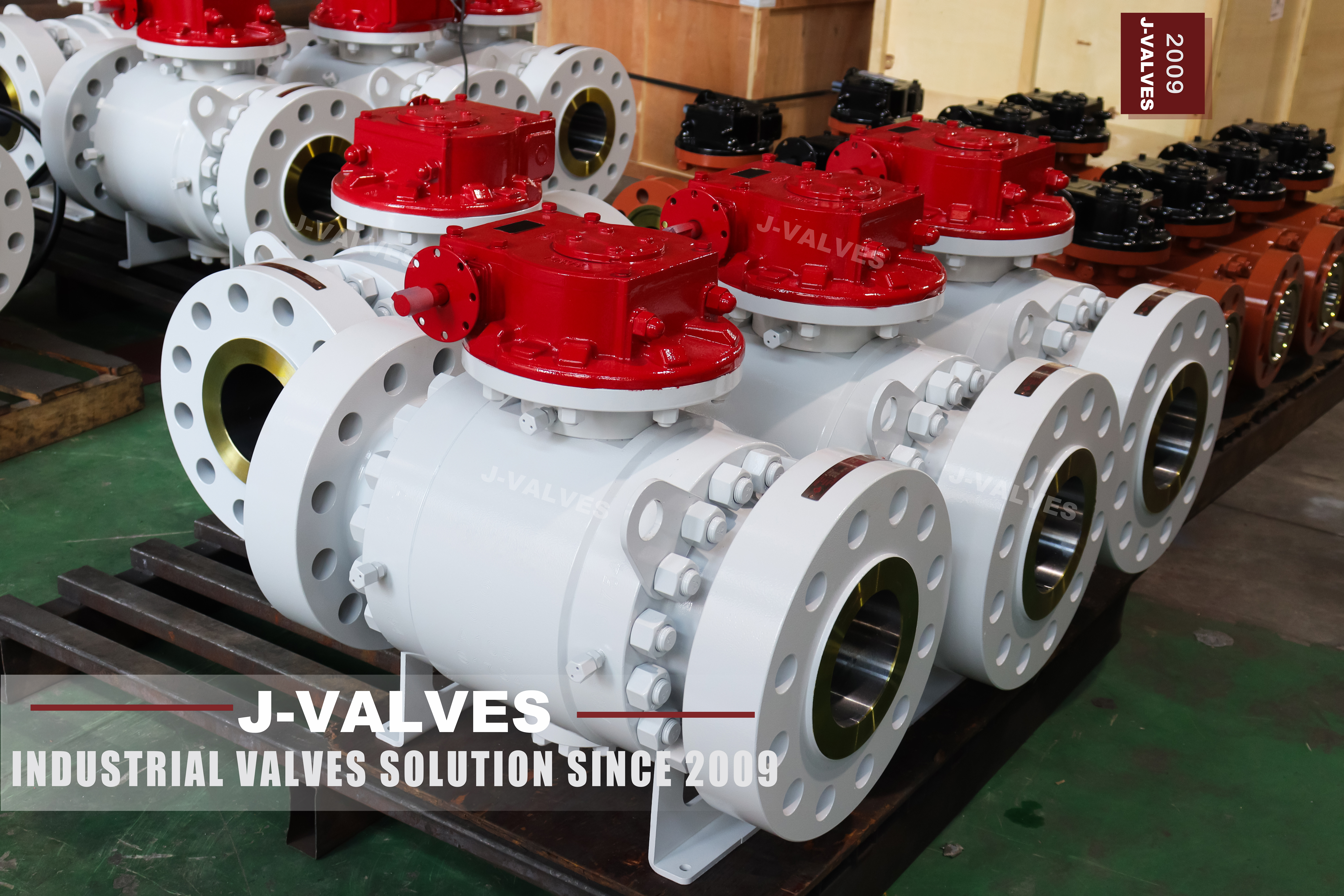
A trunnion mounted valve has three pressure boundaries and only two of them get any attention. The body joints are discussed in every quotation because they are big and visible; the stem is discussed almost never, and it is the one that moves. Every stroke of the valve works the stem seal, and every thermal cycle asks it to expand and contract against a packing that is trying to follow.
This body is forged, three pieces, with a gear on the pad and a range from two to fifty six inch at Class 150 through 2500. Inside the neck the stem is sealed in three stages rather than one: an elastomer ring as the first barrier, a second ring behind it, and a graphite gasket above both taking the fire case and the high temperature case. The three are in series, so a failure of the first does not become a leak at the second.
Two more features belong to the same story. The stem is retained by the body cover rather than by the gland, which is what makes it blowout proof in the sense API 6D means, and the gland bushing can be taken off so that the upper gasket is renewed with the valve still in service. There is also a sealant injection point on the stem, standard on this build.
That combination is the subject here: not the body, which is a forging like any other, but the one part of a trunnion valve that a maintenance team actually touches, and what it can and cannot be asked to do.
Design and Construction
The stem is a separate part from the ball. It engages the ball through a slot or a square and turns it, but it does not carry the ball's weight and it does not take the side load that line pressure puts on the ball, because that load goes into the trunnions. That separation is why a trunnion valve turns easily at a large size, and it is also why the stem can be a slender shaft with a sealing diameter that is modest compared with the bore.
The sealing stack sits inside that neck. The first barrier is an elastomer ring running on a ground stem diameter; the second is a second ring in series with the first; the third is a graphite gasket compressed by the gland. In normal service the elastomer does the work and the graphite sits behind it. In a fire the elastomer is destroyed, the graphite survives, and the valve keeps sealing long enough to be isolated, which is the behaviour API 607 is written to check.
The injection point is the fourth element and it is deliberately not a seal. A grease or sealant fitting screwed into the neck lets a maintenance team push material into the stem seal area from outside, which can stop a weep long enough to reach a shutdown. The sealant is a temporary measure and the manufacturer's own instruction is that the seal must be renewed at the first opportunity, because a seal that has been injected is a seal of unknown condition.

Material Options
The body is a forging in A105N, A350 LF2, A182 F304 or F316, or the alloy grades F11 and F22, and the choice is driven by the medium and the temperature rather than by the class. The stem follows the same logic with fewer options: A182 F316 for ordinary duty, 17-4PH where the drive end has to resist wear, and a nickel based alloy where the service is hot and corrosive.
The elastomer in the stem stack is where a specification often goes quiet. Nitrile is adequate for water and hydrocarbons at moderate temperature, a fluorocarbon elastomer covers a wider temperature range and more aggressive media, and perfluoroelastomer is used where nothing else survives, at a price. The graphite gasket above them is not affected by that choice, which is the point of having both.
| Component | Standard Build | Options | What It Decides |
|---|---|---|---|
| Body and caps | ASTM A105N forging | A350 LF2, A182 F304 or F316, F11, F22 | Medium and temperature |
| Ball | A182 F304 or F316, hard faced | Carbide coating | Erosion at the seat line |
| Seat | A182 F304 or F316, hard faced | Metal to metal | Temperature and abrasion |
| Stem | A182 F316 | 17-4PH, nickel based alloy | Wear at the drive and the seal |
| Stem seal, first barrier | Fluorocarbon elastomer ring | Nitrile, perfluoroelastomer | The everyday leak path |
| Stem seal, second barrier | Elastomer ring in series | Perfluoroelastomer | Redundancy behind the first |
| Stem seal, fire barrier | Flexible graphite gasket | Braided graphite | Survival after the elastomer is gone |
| Gland | Bolted bushing over the gasket | Extended gland for insulation | Whether the upper seal can be renewed live |
The bolting is worth a line because it is part of the same thermal story. A193 B7 with A194 2H suits a carbon body and a moderate temperature; B8M with 8M matches a stainless body's expansion. On a valve that sees cycling, a bolt set that expands differently from the body is a joint that loosens.
Technical Specifications
The family statement is two to fifty six inch, Class 150 to 2500, flanged to ASME B16.5, forged body, trunnion ball, gear or actuator on the pad. The stem assembly is common across that range, which is why this page can describe it once rather than per size.
What changes with size is the torque and therefore the operator, and what changes with class is the wall. Neither changes the sealing principle. That is the useful thing to know when a buyer is comparing two quotations at different sizes: the stem stack in a four inch valve is the same design as the one in a twenty four inch valve, and the difference in price is in the body, the ball and the gear.
| Item | Value |
|---|---|
| Size range | Two inch to fifty six inch |
| Pressure class | Class 150, 300, 600, 900, 1500, 2500 |
| Body style | Three piece forged body, trunnion mounted ball |
| Stem | A182 F316, blowout proof, retained by the body cover |
| Stem sealing | Two elastomer rings in series plus a graphite gasket |
| Injection | Stem sealant injection point, standard on this build |
| Gland | Bolted bushing, removable for live renewal of the upper gasket |
| Flange | ASME B16.5, raised face or ring joint |
| Temperature | Minus 29 to plus 425 C; the elastomer, not the body, sets the low end |
| Operator | Worm gear as photographed; lever, actuator or bare pad on request |
| Test | API 598 shell and seat, stem seal checked at test |
| Product standard | API 6D; ASME B16.34 for wall and rating |
The low temperature limit deserves its own sentence. The body grade may be good to a lower figure than the seals, and it is the elastomer in the stem that usually sets the floor. A valve ordered for a cold service has to have that line examined, because a body that is rated to the temperature with a seal that is not is a valve that will weep on the first cold night.
Standards and Compliance
API 6D requires the stem to be blowout proof, which is a structural requirement rather than a sealing one: the stem must be retained so that it cannot be ejected by pressure if the gland is removed or fails. On this design the retention is the body cover, and the gland above it can be dismantled without releasing the stem. That is the detail to point at when a buyer asks whether a valve is genuinely blowout proof or merely has a retaining ring.
Fire performance comes from the graphite gasket in the stack. API 607 is the test, ISO 10497 is the equivalent, and the certificate states the size and class it covers. The graphite is also what allows the packing to be qualified to an emission standard, where the tightness and endurance classes are printed on the report rather than summarised as a logo.
| Requirement | Document | What It Means Here |
|---|---|---|
| Blowout proof stem | API 6D | Retention by the body cover, not by the gland |
| Fire test | API 607 or ISO 10497 | Graphite gasket survives the elastomer |
| Emission qualification | ISO 15848 on request | Tightness and endurance classes on the report |
| Pressure testing | API 598 | Shell, seat and stem seal checked |
| Wall and rating | ASME B16.34 | Class converted at the design temperature |
| Material certificate | EN 10204 3.1 | Body, stem and trim |
| Sour service | NACE MR0175 on request | Hardness limits on stem and trim |
Manufacturing Process
The stem starts as bar stock that is turned to a stepped profile, with the sealing diameter ground rather than turned because an elastomer ring needs a surface finish it can wipe against. The drive end is milled to the square or the keyway that engages the ball, and the shoulder that the cover retains is machined as one diameter so that the blowout feature is a property of the part rather than of the assembly.
The neck of the body is bored and the cover face is machined square to it, because the stem has to run true inside the packing for the rings to seat evenly. A stem that is a few hundredths out of line will seal when new and weep after a hundred cycles, and the fault will be found at the gland rather than at the bore that caused it.
Assembly of the stack is the part that is easiest to get wrong. The rings go in one at a time, in the right order, lubricated with what the seal maker specifies rather than with whatever is on the bench, and the gland is brought down evenly. The graphite gasket is compressed to a figure, not to a feel, and then the stem is turned through its quarter a few times before the leak test so that the rings settle where they will run.

Quality Control and Testing
The stem seal is checked during the shell test rather than after it, because the shell test pressurises the body with the ball part open and the stem is then under the same pressure as the joints. Any weep at the gland appears at that moment, which is the right time to find it: the valve is still on the bench, the actuator is not fitted, and the fix is a gland adjustment rather than a return.
| Step | Check | Acceptance |
|---|---|---|
| 1 Incoming | Heat number against the mill certificate | EN 10204 3.1, body and stem |
| 2 Stem | Sealing diameter finish, drive dimensions | Drawing tolerance, ground finish |
| 3 Neck | Bore squareness to the cover face | Drawing tolerance |
| 4 Stack | Ring order, lubrication, gland compression | Assembly instruction |
| 5 Shell test | Body, joints and stem seal at 1.5 times | API 598, no leakage at the gland |
| 6 Seat test | Each seat at 1.1 times, cavity vented | API 598 |
| 7 Function | Quarter turn, gear indicator, injection point clear | Works standard |
| 8 Final | Gland set, caps fitted, ports plugged and marked | Works standard |
The injection point is checked for being clear before the valve ships, which sounds trivial and is not. A fitting that was painted over or filled with grease at assembly is a fitting that will not accept sealant on the night it is needed, and the person who discovers that is standing next to a leaking gland with a spanner.

Applications and Industry Service
This body is bought for high class, high value duties where taking the valve out of the line is expensive: offshore topsides, hydrocarbon export lines, amine and glycol systems, and high temperature steam where the trim has to be metal. In all of those the stem seal is the part that decides whether the valve reaches its first planned shutdown without a weep.
The geared build in the photographs is the large size configuration. A gear multiplies the hand force, and the position indicator on the housing tells the operator where the ball is; what the gear does not do is protect the stem from being forced past its stop, which is why the instruction to stop at the stop matters more on a geared valve than on a lever one.

Installation, Operation and Maintenance
Fit the operator after the line is flushed, not before. Debris that passes a partly open ball can score the seat and the stem seal at the same time, and a gear that has been fitted early is a gear that has to be removed again to clean the bore. Leave the valve fully open or fully closed during flushing rather than throttled, because a ball valve is not a control valve and a half open ball is a wear item.
Operate through the quarter turn and stop at the stop. The stem seal sees one pressure cycle per stroke, and a valve that is exercised monthly will outlast a valve that is left in one position for years and then forced, because the elastomer that never moves takes a set and the one that moves keeps its shape.
When the gland weeps, the first response is to bring the gland down evenly a little at a time, not to tighten one side. If the leak persists, the sealant injection point will buy time to the next shutdown, and the honest repair is a new set of rings with the line isolated. The upper gasket can be renewed with the valve in service by removing the gland bushing, which is a job for a fitter who has done it before and not for a first attempt at pressure.
How to Specify and Order
Six lines fix the valve: size and class, body grade, seat material, flange facing, the operator, and the stem seal materials. The last one is usually left to the supplier and it is the one that decides the low temperature limit, so it belongs on the order as an explicit requirement rather than as an assumption.
Four questions are about the line: the medium, the design temperature, the operating pressure, and how often the valve will be cycled. The medium decides the elastomer, the temperature decides whether elastomer is usable at all, the pressure decides the class, and the cycling decides whether the gland will need attention between shutdowns.
Documents worth naming: EN 10204 3.1 for body, stem and trim, the shell and seat test record with the stem seal result, the fire certificate with its scope, and the emission report where an ISO 15848 class was specified. All are available; the order is the only place that asks for them.
FAQ
Q: Why three barriers on a stem?
A: Because the stem is the only boundary on a trunnion valve that moves. The first elastomer ring does the everyday work, the second sits behind it in series so a single failure is not a leak, and the graphite gasket above both is what survives a fire when the elastomer is destroyed.
Q: What does blowout proof actually mean?
A: It is a structural requirement rather than a sealing one. The stem must be retained so that it cannot be ejected by pressure if the gland is removed or fails. On this design the retention is the bolted body cover under the gland, which is why the gland can be dismantled without releasing the stem.
Q: Can the stem seal be repaired with the valve in service?
A: The gland can be tightened live, and the upper gasket can be renewed by removing the gland bushing with the valve in service. Replacing the elastomer rings is not a live job: the line has to be isolated and the cavity vented before the stem is disturbed.
Q: What is the injection point for?
A: It pushes sealant into the stem seal area from outside to stop a weep long enough to reach a planned shutdown. It is a temporary measure, not a repair, and the seal has to be renewed at the first opportunity because an injected seal is a seal of unknown condition.
Q: Does the elastomer limit the temperature range?
A: Yes on the low side and partly on the high side. The body grade and the graphite gasket may be good to a lower and a higher figure than the elastomer can take, and the lowest limit in the stack is what governs the service. That is why a cold service order has to name the elastomer.


Hot Products


News
Reading A Ball Valve GA Drawing: The Five Dimensions That Decide Whether It Fits
A GA drawing is approved for its outline and lost on its section. The five dimensions that decide whether the valve fits, bolts and can be operated.
Read More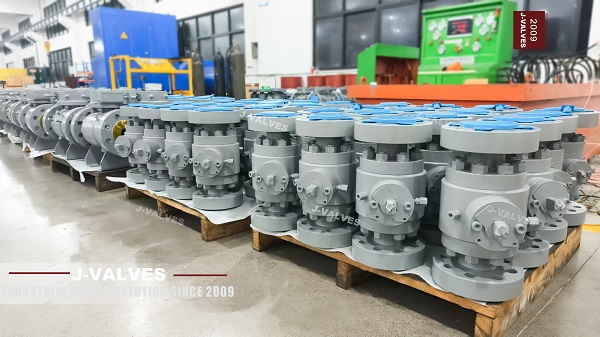
Stainless Steel Ball Valve Grades: 304, 316 And 316L, And What Actually Decides
Molybdenum is the difference that decides the duty, carbon is the difference that gets missed, and the chloride in the line matters more than the price.
Read More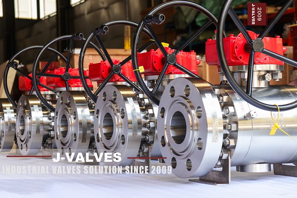
Ball Valve Spare Parts for Overseas Projects: The Wear Part List, The Quantity Math, And Four Traps
Why isolation valves fail on calendar time, not cycles. Wear part lists, Poisson stock maths, seat kit traps and the clauses that decide year six.
Read More
Ball Valves On A Bottom Loading Gantry: Creep, Dry Break And The Test That Proves Neither
A loading gantry cycles a ball valve far more than it is designed for and still cannot prove shut-off. Where creep starts, and what to specify.
Read More