

CHINA J-VALVES Offers Various High-quality I ndustrial Ball Valves
J-VALVES, a distinguished professional ball valve manufacturer rooted in China, takes pride in its extensive product portfolio. Our offerings span a wide range, including trunnion-mounted ball valves, floating ball valves, high-temperature ball valves, high-pressure ball valves, metal-sealed ball valves, ultra-low temperature ball valves, DBB ball valves, Three-way And Four-way Ball Valve, and fully welded ball valves. Each product is a testament to our commitment to precision engineering and reliable performance. Meticulously crafted, they are designed to not only meet but exceed the most stringent industrial demands, ensuring stable operation even under extreme conditions. This enables us to provide our clients with high-value services and makes our valves widely sought-after in industries.
Product Category
Contact Us


-
J-VALVES-Q47F
-
J-VALVES
Overview of the J-VALVES 8 inch Class 2500 F316 trunnion ball valve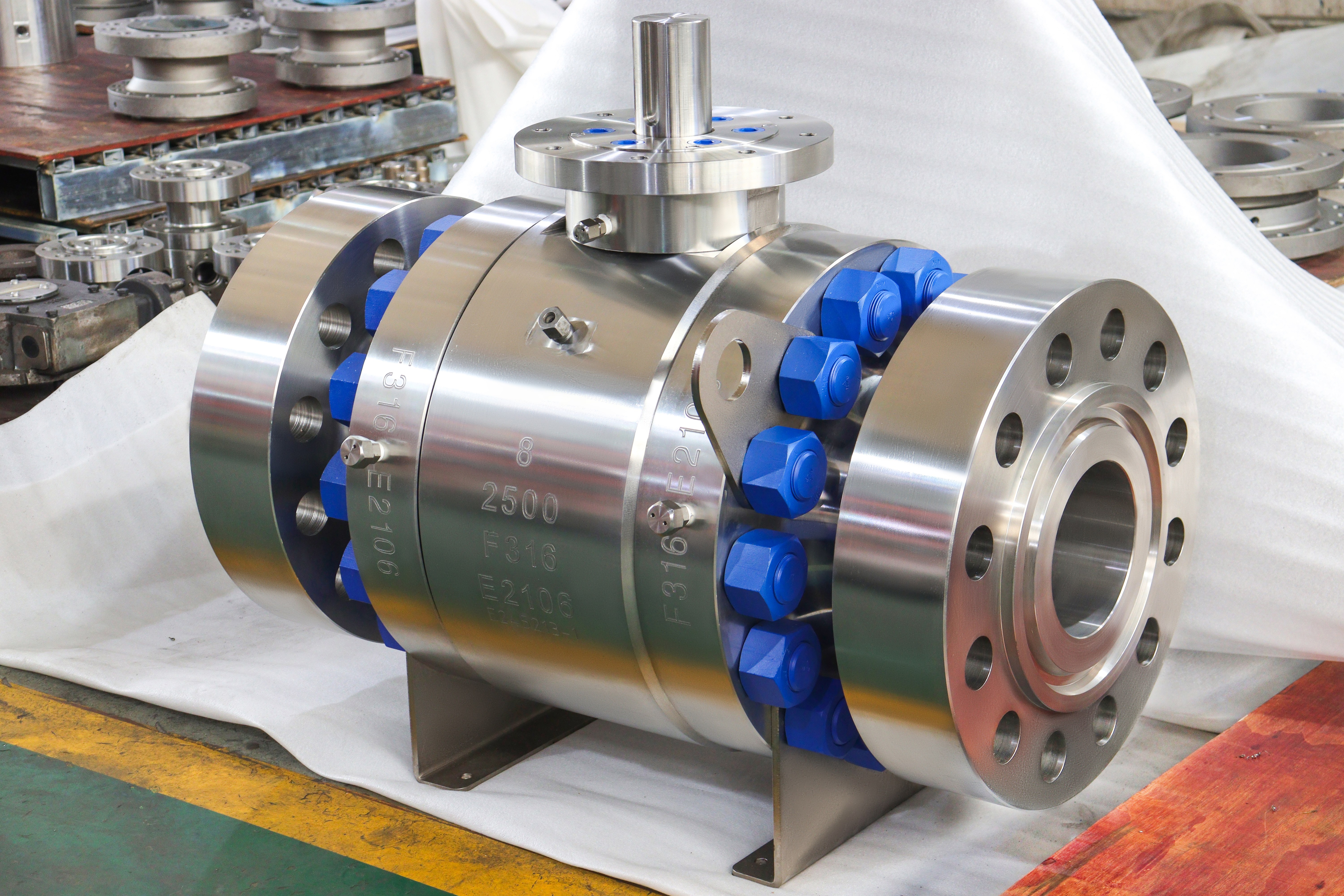
At Class 2500 the design is the easy half of the job. An eight inch body in A182 F316 sits in group 2.2 of ASME B16.34, where Class 2500 reads 6000 psi at 38 C, and a wall thick enough for that is a calculation, not an invention. What is hard is proving it. A 2500 class valve is bought on the strength of a test record, and the record is worth exactly as much as the procedure behind it.
This build is a three piece forged body with both trunnion bearings in the centre section, a metal seated ball, ring joint flanges to ASME B16.5, and a bare stem on a mounting pad in the photographs. The body is machined all over, the caps carry their own stud rings, and there is a lifting eye welded to the top of the centre section because at this class the valve is too heavy to be handled by hand.
Three tests decide whether it leaves the works: a shell test at one and a half times the rating with the ball part open, a seat test at one and one tenth with the cavity vented, and a fire test that is a type test on a sample rather than a test on this valve. The shell test asks whether the body and both joints hold. The seat test asks a narrower and harder question, because the seat here is metal.
That is the theme of this page. Not the size, which is a line on an order, but the sequence of evidence that turns a 2500 class claim into a valve somebody can put in a hydrogen, gas injection or high pressure separator line without worrying about the day it is commissioned.
Design and Construction
The centre section carries the ball, both seats and both bearing blocks, and it is the part that never comes apart. At 2500 the seat load is large, so the ball must be held rather than allowed to float: the trunnions take the thrust that the pressure puts on the ball, and the stem only turns it. If the ball were free to move, the seat would have to absorb a force it cannot survive at this class, and the seal would fail in the direction the flow happens to run.
Each cap closes on its own spiral wound gasket and its own stud ring, and both joints see full line pressure. The body is a forging rather than a casting because at this wall thickness a shrinkage void is not a cosmetic defect, it is a leak path that no amount of examination reliably finds. The forging is examined ultrasonically to ASTM A388 where the order asks for it, and the report travels with the certificate.
The metal seat is the part that changes the behaviour. There is no soft insert to conform to the ball, so sealing depends on a lapped contact between two hard surfaces, held together by a spring pack and then loaded further by the line pressure. That contact needs a small clearance to move in, and the clearance is the leak path when the surfaces are not square to each other. Everything in the machining of this valve is aimed at keeping that contact true.

Material Options
A182 F316 is the austenitic stainless forging grade used for the body and caps, and it belongs to group 2.2 with F304. The low carbon versions, F316L and F304L, are in group 2.3 and carry a lower rating at the same class, so substituting an L grade into a 2500 class order quietly changes the pressure the valve is rated for. That substitution happens more often than it should, because the L grade welds more easily and is sometimes all that is on the shelf.
The trim follows the seat decision. On this build the ball and seat are F316 with a hard facing band, cobalt based for general duty or tungsten carbide where the medium carries solids. The stem is F316, with 17-4PH or a nickel based alloy available where the drive end has to be harder or the service is hot. Packing is flexible graphite because at this class the temperature range makes PTFE pointless.
| Component | Standard Build | Options | Why It Matters at 2500 |
|---|---|---|---|
| Body and caps | ASTM A182 F316 forging | F316L, F304, F51 duplex | Group 2.2 rating; L grades drop to group 2.3 |
| Ball | A182 F316, hard faced band | Tungsten carbide coating | Contact stress on a metal seat |
| Seat | A182 F316 with cobalt based facing | Carbide facing, nickel based facing | The sealing surface is the valve's weakest link |
| Stem | A182 F316 | 17-4PH, nickel based alloy | Drive strength after the gear is fitted |
| Packing | Flexible graphite | Braided graphite with alloy wire | The only packing that survives this class |
| Body joint gasket | Spiral wound, graphite filled | Ring joint gasket | Two joints, both at full line pressure |
| Bolting | A193 B8M with A194 8M | A193 B16 with A194 7 | Stainless bolting matches the body thermally |
| Lifting | Welded eye on the centre section | Lifting slings on the body | A bare 2500 body cannot be manhandled |
The bolting note in the original data sheet reads B16 over 7, which is a shorthand for two different standards rather than one: A193 B16 studs with A194 grade 7 nuts. It is worth writing out in full on a purchase order, because A193 B16 and A194 7 are alloy steel for high temperature work, while B8M and 8M are stainless and follow the body's expansion. Mixing the two sets on one valve is a corrosion cell waiting for a wet day.
Technical Specifications
The published specification is short because most of it is fixed by standards: eight inch, Class 2500, forged A182 F316, ring joint facing to ASME B16.5, metal seat, graphite packing, gear or bare pad at the top. The bore is full port on this build, which at eight inch means the ball is large and the seat contact circle is wide.
What the data sheet cannot fix is the wall, the face to face length and the weight. Wall is a B16.34 calculation against group 2.2 and the class, and it belongs on the design record. The face to face dimension is a table value from ASME B16.10, and the drawing you sign is the only place where it becomes binding. Weight is a property of the finished casting or forging and of the trim, and it is weighed rather than quoted.
| Item | Value |
|---|---|
| Size | Eight inch, DN200 |
| Pressure class | Class 2500, recorded as PN 420 in API 6D clause 7.2 |
| Body style | Three piece forged body, trunnion mounted ball |
| Body material | ASTM A182 F316, ASME B16.34 group 2.2 |
| Rating | 6000 psi at 38 C in group 2.2, falling with temperature |
| Seat | Metal to metal, hard faced, spring energised |
| Flange | ASME B16.5 Class 2500, ring joint as stated on the data sheet |
| Bore | Full port as photographed |
| Face to face | ASME B16.10 for NPS 8 Class 2500, confirmed on the signed drawing |
| Temperature | Minus 29 to plus 425 C; the group 2.2 table runs to 538 C |
| Operator | Bare stem on a mounting pad as photographed; gear or actuator per order |
| Test | API 598 shell and seat, API 6D documentation |
| Product standard | API 6D; API 608 does not reach this class |
One line needs a comment. The data sheet states a 425 C ceiling, while the group 2.2 rating table in ASME B16.34 runs to 1000 F, which is 538 C. The 425 C is the figure the packing and the hard facing are comfortable with, and it is deliberately inside the table's range rather than at its edge. Above 538 C a flanged body no longer has a rating at all, and the standard only allows butt weld ends.
Standards and Compliance
API 6D governs this valve from the design through the marking, and it is the only product standard that applies at Class 2500. API 608 stops at Class 600, so any page or certificate that lists 608 against a 2500 class valve is quoting a scope the standard does not have. ASME B16.34 sits behind both as the wall and rating document.
The fire test is where buyers most often misread a certificate. API 607 is a type test: a sample valve of a given size and class is burned and then checked, and the certificate states the range it covers. ISO 10497 is the equivalent international document, and API 6FA was withdrawn into 607 years ago, so a certificate quoting 6FA is old paper rather than a second qualification.
| Requirement | Document | What It Means Here |
|---|---|---|
| Pipeline valve design and marking | API 6D | Governing standard at this class |
| Wall thickness and rating | ASME B16.34 group 2.2 | 6000 psi at 38 C, table to 538 C |
| Flange dimensions | ASME B16.5 Class 2500 | Ring joint groove machined to the ring size ordered |
| Face to face | ASME B16.10 | Confirmed on the signed drawing |
| Pressure testing | API 598 | Shell 1.5 times, seat 1.1 times the rating |
| Fire test | API 607 or ISO 10497 | Type test with the size and class scope printed |
| Material certificate | EN 10204 3.1 | Heat number matched to the body stamp |
| Ultrasonic examination | ASTM A388 | On the forging when ordered |
Manufacturing Process
The forging starts as a billet that is cut, heated and worked until the grain follows the shape of the finished part. At eight inch and 2500 class the blank is large, the press tonnage is high, and the heat treatment after forging is what produces the grain size the certificate describes. Machining then removes a considerable volume of material, and the first operation establishes the bore axis that everything else is referenced to.
The seat pockets are the critical cut. They must be square to the bore axis and concentric with each other, because the two seats have to meet the same ball on the same circle. After machining, the sealing faces are lapped against a lapping plate and checked for contact pattern, and the ball is ground and polished to a sphere before its hard facing goes on. A metal seat that is not lapped will pass a seat test at low pressure and weep at the top of the range.
Assembly is a torque exercise followed by a test. The gaskets go in dry, the studs are brought up in a cross pattern in stages to the drawing figure, and the gear or the pad plate is fitted so the indicator agrees with the ball position. The valve then goes onto the bench, where the shell test applies pressure to both joints and the stem at once, and the seat test is run in the direction the seat is designed to hold.

Quality Control and Testing
The test sequence is the product at this class, so it is worth stating in order. The shell test is run with the ball part open so that both body joints and the stem seal are loaded together, and the acceptance is no leakage at one and a half times the rating. The seat test follows at one and one tenth, with the cavity vented so the reading describes the seat rather than trapped pressure, and it is run once per seat.
Direction matters. A single piston effect seat is designed to hold pressure from one side and to relieve the cavity to the other, so testing it from both sides is not the same test twice; it is one valid test and one that does not mean what it appears to. A double piston effect seat holds from both sides and must be tested from both. The seat arrangement on the order decides which procedure is correct, and the record should say which was run.
| Step | Check | Acceptance |
|---|---|---|
| 1 Incoming | Heat number against the mill certificate | EN 10204 3.1, F316 chemistry and tensile |
| 2 Forging | Ultrasonic examination when ordered | ASTM A388, no reportable indication |
| 3 Machining | Seat pocket squareness and concentricity | Drawing tolerance |
| 4 Lapping | Seat contact pattern, ball sphericity | Full contact band, no gaps |
| 5 Shell test | Body, both joints, stem at 1.5 times | API 598, no leakage |
| 6 Seat test | Each seat at 1.1 times in its design direction | API 598; metal seat to the stated rate |
| 7 Function | Quarter turn, stop position, pad or gear fit | Works standard |
| 8 Final | Cavity drained, bore dried, faces protected, caps | Works standard |
The seat acceptance for a metal seat is a leakage rate rather than zero, and that is a property of the standard, not a concession by the maker. A buyer who needs tighter than the standard for a specific service has to write the tighter figure into the order, and it will be quoted against a different lapping and inspection regime, which is why the two should never be assumed to be the same product.

Applications and Industry Service
Eight inch at Class 2500 belongs to the parts of a plant where pressure is the design case rather than the operating condition: gas injection and re-injection, high pressure separators, wellhead and manifold work, and the discharge side of high ratio compressors. In all of those the valve is closed for long periods and has to open on the first command, which is why the seat and the stem seal, not the bore, are what the buyer is really purchasing.
Metal seating is chosen here because the temperature and the medium rule out a soft insert. Where the same valve is used on clean dry gas at moderate temperature, a soft seat would seal better and cost less, but the class usually arrives with a temperature that makes that impossible. The two builds are not interchangeable and the order has to say which one.
It is also a valve that is bought in small numbers and held for a long time. That changes the specification conversation: spares for a 2500 class body are specific to the size and class, the ring joint gasket is a purchased item with its own number, and the seat is lapped to the ball it will run against. A spare seat on the shelf is not a spare seat until it has been matched to a ball.
Installation, Operation and Maintenance
A ring joint joint is made once and remade with a new ring. The groove must be clean, dry and free of the previous ring's marks, the ring must be new and of the correct number for the flange size and class, and the studs are brought up in a cross pattern to the drawing torque. Reusing a ring that has already been crushed is the single most common cause of a weep at commissioning on this type of joint.
Do not use the valve as a test blind. A 2500 class valve closed against a rising cavity pressure with a metal seat and no relief path is a trap, and the thermal expansion of trapped liquid will find the weakest part of the assembly. Where the seat arrangement is double piston effect, an external relief device is part of the design, not an accessory.
The gear, where fitted, is a force multiplier and not a position guarantee. Turn it through the quarter and read the indicator, and stop when the stop is reached rather than leaning on the handwheel. The stem is retained by the body on this design, so the packing can be adjusted with the valve in service, and the upper stem seal can be renewed once the cavity has been vented.
How to Specify and Order
Six lines fix the valve: size and class, body grade with the certificate requirement, seat type and whether double piston effect is required, flange facing and ring number, the operator, and the standards the test record has to follow. On a 2500 class order two more belong on the list, which are the test direction and the seat acceptance figure, because neither is uniform across builds.
Four questions are about the line: the medium with its concentration and any solids, the design temperature, the design pressure including any transient, and the duty cycle. The medium decides whether a metal seat is required at all, the temperature decides the packing and the facing, the pressure decides the class, and the duty decides whether the valve can be left with a bare pad or needs an operator from the start.
Documents should be named rather than assumed: EN 10204 3.1 for body and trim, the shell and seat test records with the direction stated, the dimensional report, the fire certificate with its size and class scope, and the ultrasonic report on the forging if soundness has to be demonstrated. All are available on this build, and none of them arrives unless the order asks for it in writing.
FAQ
Q: What pressure is Class 2500 in F316?
A: In group 2.2 of ASME B16.34, Class 2500 reads 6000 psi at 38 C, and the figure falls as the temperature rises. The class does not change with temperature; the rating does, so the table has to be read at the design temperature rather than at ambient.
Q: Why is the seat test run in one direction only?
A: Because a single piston effect seat is built to hold from one side and to relieve the cavity to the other. Testing it from the other side is not the same test repeated, it is a test of something the seat was not designed to do. A double piston effect seat holds from both sides and is tested from both, so the seat arrangement decides the procedure.
Q: Is zero leakage achievable on a metal seat?
A: API 598 sets a leakage rate for a metal seated valve rather than zero, because a metal contact band cannot conform the way a soft insert does. A tighter figure can be specified, and it will be quoted against a different lapping and inspection regime rather than simply promised.
Q: Why does the data sheet stop at 425 C when the table goes to 538 C?
A: The 425 C is the figure the packing and the hard facing are comfortable with, and it sits inside the table rather than at its edge. Above 538 C the group 2.2 table ends and a flanged body has no rating at all, so only butt weld ends remain available.
Q: Is this valve covered by API 608?
A: No. API 608 covers flanged ball valves from DN 15 to DN 600 at classes 150 to 600, and Class 2500 is outside that range. The governing document here is API 6D, with ASME B16.34 for the wall and the rating.


Hot Products


News
Reading A Ball Valve GA Drawing: The Five Dimensions That Decide Whether It Fits
A GA drawing is approved for its outline and lost on its section. The five dimensions that decide whether the valve fits, bolts and can be operated.
Read More
Stainless Steel Ball Valve Grades: 304, 316 And 316L, And What Actually Decides
Molybdenum is the difference that decides the duty, carbon is the difference that gets missed, and the chloride in the line matters more than the price.
Read More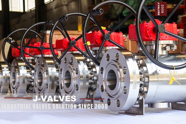
Ball Valve Spare Parts for Overseas Projects: The Wear Part List, The Quantity Math, And Four Traps
Why isolation valves fail on calendar time, not cycles. Wear part lists, Poisson stock maths, seat kit traps and the clauses that decide year six.
Read More
Ball Valves On A Bottom Loading Gantry: Creep, Dry Break And The Test That Proves Neither
A loading gantry cycles a ball valve far more than it is designed for and still cannot prove shut-off. Where creep starts, and what to specify.
Read More