


CHINA J-VALVES Offers Various High-quality I ndustrial Ball Valves
J-VALVES, a distinguished professional ball valve manufacturer rooted in China, takes pride in its extensive product portfolio. Our offerings span a wide range, including trunnion-mounted ball valves, floating ball valves, high-temperature ball valves, high-pressure ball valves, metal-sealed ball valves, ultra-low temperature ball valves, DBB ball valves, Three-way And Four-way Ball Valve, and fully welded ball valves. Each product is a testament to our commitment to precision engineering and reliable performance. Meticulously crafted, they are designed to not only meet but exceed the most stringent industrial demands, ensuring stable operation even under extreme conditions. This enables us to provide our clients with high-value services and makes our valves widely sought-after in industries.
Product Category
Contact Us


-
J-VALVES-Q947F
-
J-VALVES
Overview of the J-VALVES marine grade top entry ball valve with an extended stem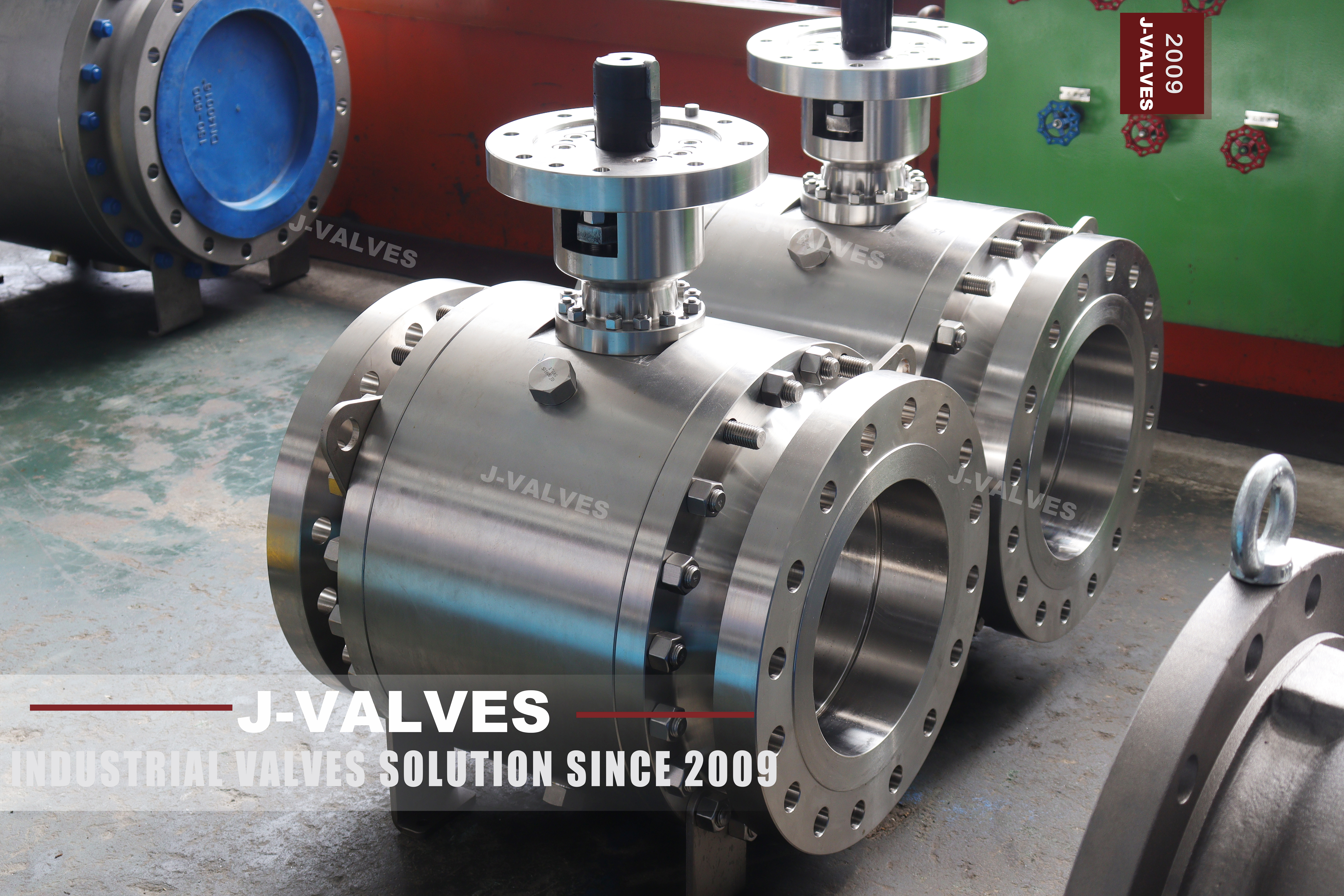
Two features decide everything about this valve, and they pull in opposite directions. Top entry means the ball, the seats and the stem can come out through a single bolted cover on top, without cutting the pipe and without taking the valve out of the line. An extended stem means the valve is installed where a person cannot stand next to it, and the operator is brought to somewhere a person can.
Put together, they set a condition that the page never states. A top entry valve is serviceable only where the top of it can be reached, and the extension is an attempt to create that place. Whether it succeeds depends on what is above the valve: a deck, a bulkhead, a cofferdam or open water.
The valve is a half inch to twenty four inch ball valve in Class 150, 300 or 600, available in carbon steel with a marine coating, in cast stainless, or in a nickel aluminium bronze. This page is about the access question and about the second thing that decides a marine valve, which is what happens when four different metals sit in sea water together.
Design and Construction
The body is one piece. There is no body joint and no bolted shell; the only opening is the top cover, which is a machined flange held by a ring of studs, with the stem passing through it. The ball is carried between two seats inside that single body, and it comes out through the top when the cover is lifted.
That construction is what a marine valve wants, because it removes every joint that could weep into a bilge. A two piece body has a gasket at the split and a row of studs through it; a top entry body has neither, and the one joint it does have is above the waterline of the valve, where a weep is visible rather than hidden.
The cover is the pressure boundary and the maintenance access at the same time, which is why it is the most heavily bolted part of the valve. Every internal part is below it: the ball, both seats, the stem and its packing. Lifting the cover is the whole teardown, and it is done with the valve still bolted in the line.
The extension rises from that cover. On the photographed valve it is a closed cylinder with a studded flange at each end, which means the stem is enclosed between the body and the drive rather than exposed. That detail matters and it is taken up again in the next section, because an enclosed extension is a different pressure arrangement from an open one.

Top Entry Only Works If the Top Is Reachable
The page says the internals can be removed from the top without cutting the pipe or removing the valve, and that is true of the valve. It is not true of the installation unless there is somewhere to stand. A top entry valve under a deck with the cover one hand's width below it is a valve that will be cut out anyway, because nobody can lift a cover they cannot get a hand to.
That is the problem the extension solves, and it solves it in four different ways depending on where the valve sits. On a deck extension the stem is brought up through the deck so that a bilge or ballast valve can be worked from above, and the operator stands on the deck. On a bulkhead penetration the stem passes through the bulkhead so that the valve can be operated from the safe side of a fire zone. On a subsea extension the stem ends at a position an ROV can reach. On an insulated extension the stem is lengthened to take the packing away from a hot line.
| Extension Type | Where the Operator Ends Up | What Has to Be True There |
|---|---|---|
| Deck extension | On the deck, above the valve | A deck penetration that is sealed and drained |
| Bulkhead penetration | On the safe side of the bulkhead | A penetration that keeps the boundary intact |
| Subsea extension | At an ROV accessible position | A top that a tool can engage without a person |
| Insulated extension | Away from the hot pipe surface | Room for the insulation and for a hand |
The arrangement on the photographed valve is the enclosed kind. The extension is a cylinder with a flange at each end, and the stem runs inside it, which means the packing cannot be at the bottom of the cylinder: it has to be at the top, above the extension, because that is the only place a gland can be adjusted. If that reading is right, the extension is part of the pressure boundary and its flange joints are pressure joints.
That is not a detail to guess at, and it belongs on the drawing rather than in a description. An open extension, with the stem visible and the packing in the body, is a different valve with a different test: the extension carries torque only, and the pressure stops at the body. An enclosed extension carries pressure up to the top gland, and it has to be shell tested as part of the body.
Seen from that angle the stud count does the work. There is one ring around the cover, one ring at the bottom of the extension and one at the top where the drive mounts. The middle ring is the one that tells you what kind of extension this is: on an open column there is no middle ring, because there is nothing to seal.
The four inch and six inch lines in the page have a gap that is worth naming. It says floating up to four inch and trunnion from six inch, and between those two numbers sits the five inch valve, which in DN terms is DN 125. A page that assigns structure by size should either cover that size or say that it is not offered, because a buyer reading it will assume the rule is continuous.
Technical Specifications
The table below is the family as the page describes it, with the size and class range narrowed to what the standards allow and the temperature range split into what each body material can actually do. The photographed unit is in a cast stainless finish; the bronze and the coated carbon steel are the other two builds, not variants of this one.
| Item | Value |
|---|---|
| Size range | Half inch to 24 inch, DN 15 to DN 600 |
| Pressure class | Class 150, 300 and 600, PN 20, PN 50 and PN 100 |
| Temperature | Minus 29 to plus 100 Celsius for the carbon and stainless builds |
| Body | A216 WCB with a marine coating, A351 CF8 or CF8M, or B148 C95800 |
| Body joints | None, single body with a bolted top cover |
| Ball | CF8M, F316, or a nickel copper alloy UNS N05500 |
| Ball support | Floating to 4 inch, trunnion from 6 inch |
| Stem | F316, 17-4PH, or UNS N05500 |
| Stem seal | PTFE V rings, graphite, or a low emission composite |
| Cover joint | Gasketed, ring of studs, the pressure boundary |
| Extension | 300 to 3000 mm standard, longer to the project drawing |
| Extension type | Deck, bulkhead, subsea, or insulated |
| Seat | RPTFE, PEEK, or metal with hardfacing |
| Ends | Raised face or ring joint flange, butt weld, socket weld, or threaded |
| Bolting | B8M stainless with a PTFE coating or hot dip galvanised |
| Operation | Lever or gear, pneumatic, electric, hydraulic, or ROV interface |
| Design | API 6D and API 608 within their limits, ASME B16.34 |
| Test | API 598 and API 6D |
Four rows need a word. The temperature row is written for the carbon and stainless builds because the page prints minus 196 to plus 100 for the whole product, and minus 196 is a cryogenic valve with a long neck and a stainless body; a bronze valve is not that valve. The bolting row is a corrosion decision as much as a mechanical one. The ball support row is the one with the gap at five inch. And the body row is the one where the photograph shows one of three possibilities.
Standards and Compliance
API 608 applies here and it is worth saying so plainly, because this family stops at Class 600 and at 24 inch, which is exactly inside the limits of that standard. It covers steel ball valves to DN 600 and Class 600, so the whole range of this page is within it, unlike the high pressure pages on the same site that cite it and should not.
| Document | What It Fixes | What It Leaves Open |
|---|---|---|
| API 608 | Design, test and marking inside DN 600 and Class 600 | The top cover bolting pattern |
| ASME B16.34 | Wall and ratings | The extension and its flanges |
| ASME B16.5 | Flange dimensions and drilling | The gasket and its material |
| ASME B16.10 | Face to face for flanged valves | The socket weld and threaded lengths |
| API 607 and ISO 10497 | The fire test as a type test | Whether the delivered unit was tested |
| NACE MR0175 | Hardness limits for sour service | Whether the service is sour |
The fire test row is the one that gets misread most often. Compliance with API 607 or ISO 10497 means a sample of the design passed a defined burn and a defined measurement afterwards. It does not mean the valve in the crate was tested, and it does not mean the valve is fire proof; it means that after the soft seat is destroyed there is a metal path that still restricts flow.
Manufacturing Process
The body is cast and then machined from the top face, because that face is the reference for everything else. The bore, the seat pockets and the stem bore are all cut relative to it, so that the cover, the seats and the stem line up when the valve is assembled. A top entry body machined from any other face arrives with a cover that has to be pulled down against a gasket it does not sit square to.
The cover is machined as a matched part, with the stud holes drilled on the same setting as the body so that the ring picks up without reaming. The stem passes through the cover in a gland that is adjustable from outside, and the packing is fitted after the cover is in place rather than before.
The extension is built as a separate assembly and bolted on. On the enclosed type the flanges at each end are machined and the cylinder is proved before assembly, because it is a pressure part; on the open type the column carries torque only and the check is straightness and coupling fit. Then the whole assembly is pressure tested as one item.
Surface preparation comes last and matters more here than on a land valve. A marine coating is only as good as the edge preparation under it, so the cast edges are rounded, the welds are dressed, and the coating is applied to a defined thickness with the flange faces masked.

Quality Control and Testing
The shell test proves the body and the cover joint together, which on a top entry valve is the whole pressure envelope. The seat test follows to API 598, and on a trunnion valve each seat is proved in the direction it is loaded. The test is done with the cover bolted to its final torque, because a cover that is only snug will pass a low pressure test and weep at rating.
The extension is checked for the two things that go wrong. The first is alignment: the stem has to run true from the body gland to the top flange, and a stem that is out of line will wear its packing on one side. The second is closure on the enclosed type, where the extension is a pressure part and is proved with the body rather than separately.
The bolting is checked for material and for coating. B8M studs in a bronze or stainless body are there to avoid a galvanic couple with the body and to avoid galling when they are undone after years in sea water, and a hot dip galvanised stud in the same hole defeats both purposes.

Applications and Industry Service
The first use is ballast and bilge service, where the valve sits low in the hull and the operator has to work from a deck. That is the case the deck extension exists for, and it is also the case where top entry pays for itself, because the alternative to lifting a cover is a dry dock.
The second use is sea water cooling and fire main systems, where the body material is chosen for the water rather than for the pressure. Nickel aluminium bronze resists both corrosion and biofouling, cast stainless resists corrosion but not fouling, and coated carbon steel is the economic choice where the water is treated.
The valve is the wrong choice where the medium is cryogenic, because the range on the page belongs to a long neck stainless build and not to the bronze one; and it is the wrong choice where nobody can reach the top, because a top entry valve that cannot be opened is a heavier single body valve with no advantage.

Installation, Operation and Maintenance
Installation is two flange joints or two weld ends, with the body supported so that the extension carries no bending load from the pipe. On a deck extension the penetration is sealed and drained, and the drain is the part that is usually forgotten: water standing around a stem is water standing in a gland.
The cover studs are tightened in a cross pattern in stages, and the gasket is a new one every time the cover comes off. A re used cover gasket on a marine valve is the most common source of a weep into a bilge, and it is invisible until the compartment is checked.
Operation is a quarter turn, by lever, gear, actuator or ROV interface. Maintenance is the gland, the seats and the cover gasket, all of which are reachable from the top. The one part that is not is the body itself, which is why the coating and the cathodic protection of the body are decided at build time rather than at maintenance time.
How to Specify and Order
The lines below are the ones the page leaves open, and the second decides whether the valve can be serviced where it is installed.
| Line on the Order | What to Write | Why It Matters |
|---|---|---|
| Body material | WCB coated, CF8M, or C95800, one of them | Three builds, three temperature ranges |
| Extension type and length | Deck, bulkhead, subsea or insulated, with the length | It decides where the operator stands |
| Extension closure | Open column or enclosed pressure column | Enclosed is shell tested with the body |
| Top access | The clear height above the cover | A cover nobody can lift is not an access |
| Bolting | B8M with a PTFE coating, not plain galvanised | Galvanic couple and galling in sea water |
| Seat | RPTFE, PEEK or metal, with the temperature | The seat sets the limit on this build |
| Fire compliance | API 607 or ISO 10497, as a type test | It is a design qualification, not a unit test |
| Ends | Flange, butt weld, socket weld or threaded | Four end types, four different lengths |
Read as a whole, the page describes a valve whose advantage is access, installed in places where access is the hardest thing to get. Top entry removes the body joint and puts every wearing part under one cover. The extension tries to bring that cover to a place where a person can stand, and whether it does is a question about the ship rather than about the valve.
FAQ
Q: What does top entry actually save on a marine valve?
A: The body joint and the dry dock. Every wearing part, the ball, both seats, the stem and the packing, sits under one bolted cover, so the valve can be rebuilt with the pipe still connected and the hull still afloat. A two piece body achieves the same access but keeps a gasketed split below the cover, and that split is where a weep into a bilge starts.
Q: Is an extended stem the same as a top entry access?
A: No, and the difference is the point of this page. The extension moves the operator to where a person can stand; the cover still has to be lifted to replace the seats, and lifting it needs clear space above it. A top entry valve with a deck extension works because the cover is at deck level. The same valve under a low deck without an extension cannot be opened at all.
Q: Is the extension a pressure part?
A: It depends on the construction, and the page does not say. On the photographed valve the extension is a closed cylinder with a studded flange at each end, which puts the packing at the top and makes the extension part of the pressure boundary, so it is shell tested with the body. On an open column the stem is exposed and the packing stays in the body, so the column carries torque only.
Q: Does the minus 196 degree figure apply to the bronze body?
A: No. The page prints one temperature range for the whole product, but minus 196 is a cryogenic valve with a long neck and a stainless body. A C95800 nickel aluminium bronze body is a sea water material for ambient service, and the cast stainless build is the one that goes cold. The temperature has to be read against the body material, not against the family.
Q: Why B8M studs rather than galvanised steel?
A: Because of the two things that happen to a fastener in sea water. A plain steel stud in a bronze or stainless body forms a galvanic couple and corrodes at the thread, and a stainless stud without a coating galls when it is undone after years in service. B8M with a PTFE coating addresses both, which is why the stud material belongs on the order and not in a footnote.


Hot Products


News
Urea Plant Ball Valves: The Wetted Path Survives Only While Oxygen Is Being Fed To It
Carbamate at 150 bar and 185 C eats stainless 50 times faster once the passive film starves. The valve cavity is where the oxygen runs out first.
Read More
Stiction: What A Ball Valve Becomes When Nobody Turns It
A valve that stood closed for years has not worn out. The seat has bonded to the ball, and the first stroke is a step, not a ramp. What the trace shows.
Read More
Molten Salt Ball Valves: The Valve Works at 565 C And Dies at 219 C
Salt freezes at 220 C and decomposes at 565 C. Everything a molten salt ball valve does happens in that 345 kelvin gap, and the gap is not generous.
Read More
Direct Air Capture Ball Valves The Vacuum Side Runs The Seal Backwards, And Three Hundred Thousand Strokes Decide The Design
A solid sorbent DAC plant moves 1.3 million cubic metres of air per tonne of CO2, then asks a DN50 ball valve to hold 0.9 bar from the wrong side.
Read More