


CHINA J-VALVES Offers Various High-quality I ndustrial Ball Valves
J-VALVES, a distinguished professional ball valve manufacturer rooted in China, takes pride in its extensive product portfolio. Our offerings span a wide range, including trunnion-mounted ball valves, floating ball valves, high-temperature ball valves, high-pressure ball valves, metal-sealed ball valves, ultra-low temperature ball valves, DBB ball valves, Three-way And Four-way Ball Valve, and fully welded ball valves. Each product is a testament to our commitment to precision engineering and reliable performance. Meticulously crafted, they are designed to not only meet but exceed the most stringent industrial demands, ensuring stable operation even under extreme conditions. This enables us to provide our clients with high-value services and makes our valves widely sought-after in industries.
Product Category
Contact Us


Pressure Class: PN16, 16 bar at 20 C, EN 1092-1 flanges
Body Material ASTM A351 CF8 (cast 304), three-piece bolted
Ball Material: CF8 hard chrome plated, 316 optional
Stem: 304 / 316, blow-out proof, anti-static
Seat Material: PTFE, RPTFE, PPL, PEEK
Service Temperature: -29 to +180 C (PTFE), +250 C (PPL), +260 C (PEEK)
Port Configuration: L-port diverter or T-port mixer / splitter
End Connection: Flanged RF, EN 1092-1 PN16
Actuation: Rack and pinion pneumatic, double acting or spring return
Air Supply: 4 to 7 bar, filtered and dry
Mounting Pad: ISO 5211 F10 / F12, 19 mm square drive
Break Torque: 170 N.m at full PN16 differential, PTFE seat
Flow Coefficient: Kv 360 m3/h L-port, 290 m3/h T-port
Design Standard: ASME B16.34, API 608
Test Standard: API 598 / EN 12266-1, three-port seat test
Leakage Class: ISO 5208 rate A, soft seat
Options: Solenoid, limit switch, filter regulator, manual override, electric actuator
-
Q644F
-
J-VALVES

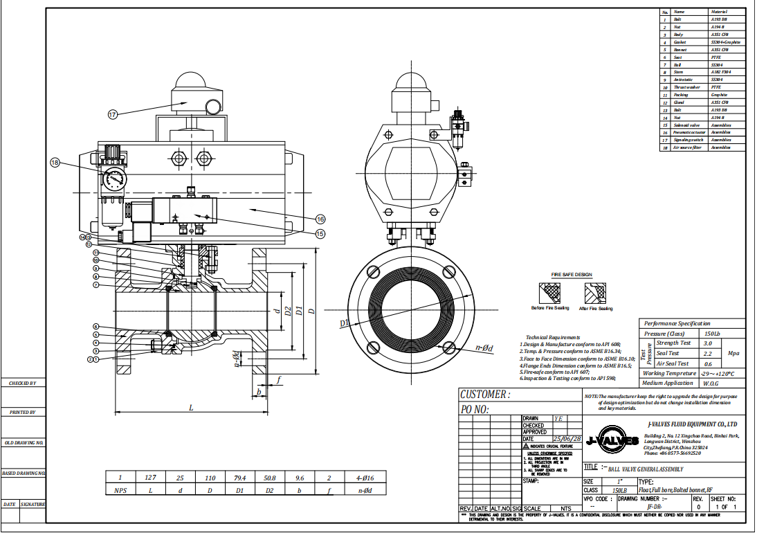
A pneumatic three-way ball valve is a quarter-turn valve with three flanged ports and an air actuator that turns the ball through 90° or 180°, so one valve can divert a flow between two outlets, merge two inlets, or blend a third stream into a main line. The 4 inch (DN100) PN16 CF8 version described here carries a floating 304 stainless ball on PTFE, RPTFE or PPL seats, bolts to EN 1092-1 PN16 flanges, and is driven by a rack-and-pinion cylinder working at 4 to 7 bar air.
It replaces two on/off valves and a tee on water, HVAC changeover, filtration and dilute chemical duty, and it does so with one actuator, one set of limit switches and one line in the maintenance register. J-VALVES builds three-way ball valves from DN15 to DN300 in Wenzhou, Zhejiang, and sizes the actuator on measured torque rather than on a catalogue average. This page sets out the port logic, what PN16 actually fixes, the seat limits that decide the real temperature rating, the torque and air arithmetic behind actuator selection, and the three-port seat test that most three-way valves never receive.

Key facts at a glance
Item | Value for this valve |
|---|---|
Size | 4 inch / DN100 (range DN15 to DN300) |
Pressure class | PN16, 16 bar at 20 °C, EN 1092-1 flanges |
Body | ASTM A351 CF8 cast stainless (304), three-piece bolted |
Ball | CF8, hard chrome plated; 316 ball optional |
Stem | 304 or 316, blow-out proof, anti-static |
Seat | PTFE, RPTFE, PPL or PEEK |
Temperature | -29 to +180 °C on PTFE; +250 °C on PPL; +260 °C on PEEK |
Port | L-port (diverter) or T-port (mixer / splitter) |
Ends | Flanged raised face, EN 1092-1 PN16 |
Actuation | Double acting or spring return rack and pinion, 4 to 7 bar |
Standards | ASME B16.34, API 608, API 598 / EN 12266-1 |
Leakage | ISO 5208 rate A on each of the three seats |
L-port or T-port: decide the port before the actuator
The ball passage, not the body, decides what the valve can do, and the two standard passages are not interchangeable at commissioning time. An L-port ball has two openings set 90° apart, so it connects port 1 to port 2, then port 2 to port 3 after a quarter turn. It never connects all three ports and it never cross-connects 1 and 3 directly. A T-port ball has a straight passage with a branch at 90°, so at mid-travel it connects all three ports and can split or blend, while at the end positions it connects two of the three.
Port | Passage | Positions on a 90° actuator | Positions on a 180° actuator | Function | Typical duty |
|---|---|---|---|---|---|
L-port | Two ports 90° apart | 1-2 and 2-3 | Same two positions | Divert, select | Duty and standby pumps, duplex filters, two-tank selection |
T-port | Tee passage | 1-2-3 all open; 1-3 through with 2 blocked | Four positions: 1-2-3, 1-3, 1-2, 2-3 | Mix, split, cross-over | Blending, dosing injection, bypass around a heat exchanger |
The trap is the actuator stroke. A T-port ball that must reach the cross-over position needs 180° of travel, and a standard 90° rack-and-pinion cannot deliver it. There are two honest routes: order a 180° cylinder, or use an L-port ball where the process only needs diverting. Ordering a 90° spring-return unit against a T-port duty that assumes cross-over leaves the valve permanently one position short, and the error usually surfaces during commissioning rather than at the factory test.
Write the port into the tag number. "Three-way, T-port, 180°, fail to 1-2-3" is a specification. "Three-way ball valve" is not.
What three ports do to the mechanics
A three-way body is a two-way body with a third branch and a second seat, and that second seat is where the engineering changes.
Two seats carry load at once. On a two-way floating valve the line pressure drives the ball into one downstream seat. On a three-way valve the same pressure can act on two seats simultaneously, so break-to-open torque is typically 1.5 to 1.8 times that of a two-way valve of the same bore and class. This is the most common reason a three-way valve arrives with an actuator that stalls on site.
The cavity has nowhere to vent. When the ball blocks a port, the space between the two seats and the blocked branch becomes a closed liquid volume. Water in a rigid steel cavity gains roughly 4 to 5 bar for every 1 °C of temperature rise, because its bulk modulus is about 2.2 GPa and its volumetric expansion about 2×10⁻⁴ per °C. A cavity full of cold water that warms to ambient overnight can lift the seats off the ball or lock the valve solid. The fix is a pressure-relief hole drilled through the upstream side of the ball, or a self-relieving seat, and it has to be asked for: the hole is invisible on a general arrangement drawing and it is not on a stock valve.
Floating is correct at this size, and only at this size. A floating ball seals because pressure drives the ball into the downstream seat, and that seat load grows with the square of the bore and linearly with pressure. The practical ceiling is around DN150 at PN16 and DN100 at PN40. A 4 inch PN16 valve sits comfortably inside that envelope; a 6 inch PN40 three-way does not, and needs a trunnion ball with spring-loaded seats instead.
Anti-static and blow-out proof. A ball electrically isolated from the body can hold a charge in flammable service, so a spring-loaded contact keeps ball-to-body resistance below 10 Ω. The stem is shouldered so it cannot leave the body if the gland is dismantled under pressure.
PN16 and CF8: what the combination actually buys
Two different numbers hide behind "PN16". The first is the flange rating, 16 bar at the EN 1092-1 reference temperature of 20 °C. The second is the allowable pressure of the assembled valve at the service temperature, which falls as the seat reaches its limit. On a soft-seated valve the seat governs long before the flange does, so the figure on the nameplate is not the figure available in the line.
PN16 flanges are also not Class 150 flanges, even though the two are quoted as equivalent in most Chinese catalogues. At DN100 the PN16 flange is 220 mm outside diameter on a 180 mm bolt circle with eight Ø18 holes. The 4 inch Class 150 flange is 228.6 mm on a 190.5 mm bolt circle with eight Ø19 holes. The bolt circles differ by 10.5 mm, so a PN16 valve will not bolt to a Class 150 counter-flange without an adapter. State the flange standard, not only the class name.
Flange standard | DN100 / 4 inch OD | Bolt circle | Bolting | Thickness |
|---|---|---|---|---|
EN 1092-1 PN16 | 220 mm | 180 mm | 8 × Ø18 | 20 mm |
ASME B16.5 Class 150 | 228.6 mm | 190.5 mm | 8 × Ø19 | 23.9 mm |
CF8 to ASTM A351 is the cast equivalent of 304: 18 to 21 % chromium, 8 to 11 % nickel, 0.08 % maximum carbon, 485 MPa minimum tensile and 205 MPa minimum yield. It is the right body for potable water, chilled and hot water, weak acids and alkalis, food-grade water and general utility duty. It is the wrong body for chloride-bearing water above about 60 °C, for hypochlorite dosing, and for anything to be welded into a line where the heat-affected zone must stay corrosion resistant. Those duties go to CF8M or CF3M, which is the subject of the sister page in this batch.
The three-piece body is a maintenance decision rather than a pressure one. Two end caps bolt to a centre section, so the ball, seats and stem can be replaced with the body left in the line and the pipe broken at one joint only. On a valve at the bottom of a plant room, or buried in a skid, that is half a day of work against two.
The seat sets the temperature, not the body
Most catalogues in this category print a temperature range that belongs to the body material, and buyers then specify a PTFE-seated valve for 300 °C steam service. The table below is the seat truth, and it is the one to quote.
Seat | Service range | Behaviour | Torque factor |
|---|---|---|---|
PTFE | -29 to +180 °C | Best sealing and lowest torque, cold flows under sustained load | 1.0 |
RPTFE, glass or carbon filled | -29 to +180 °C | Less cold flow, better wear resistance, slightly stiffer | 1.1 to 1.2 |
PPL | -29 to +250 °C | Holds load at steam temperature, needs more actuator margin | 1.3 to 1.5 |
PEEK | -40 to +260 °C | Best for cycling and clean high temperature duty, hardest seat | 1.5 to 1.8 |
Metal, Stellite faced | to +425 °C and above | Fire-safe and abrasive duty, leakage far worse than a soft seat | 2.0 and up |
A valve advertised as "-29 to +425 °C" with PTFE seats is quoting a body-material envelope, not a valve rating. At 4 inch PN16 the defensible figures are -29 to +180 °C on PTFE and RPTFE, -29 to +250 °C on PPL, and +260 °C on PEEK. Saturated steam at 16 bar is 201 °C, so a PN16 soft-seated three-way valve is not a 16 bar steam valve; it is a 10 bar steam valve at best, and only with PPL or PEEK in it.
On the cold side, -29 °C is a PTFE limit, not a stainless limit. Below that the seat takes a compression set on the first cycle and leaks on the second, which is why genuine low-temperature three-way valves use PCTFE seats and an extended stem.
Flow capacity: a three-way Kv is not a two-way Kv
Kv is the water flow in m³/h at 20 °C that gives a 1 bar pressure drop across a fully open valve. Cv is the same quantity in US gpm at 1 psi, and Cv is about 1.156 times Kv. A three-way ball throttles itself: the side port is smaller than the bore, the ball carries two sealing lands, and a T-port passage splits into two openings. The result is a Kv of roughly 55 to 65 % of a full-bore two-way valve of the same size.
Size | DN | Kv L-port (m³/h) | Kv T-port (m³/h) | Cv L-port | Break torque, PTFE at PN16 |
|---|---|---|---|---|---|
1 inch | 25 | 22 | 18 | 25 | 12 N·m |
1-1/2 inch | 40 | 55 | 45 | 64 | 30 N·m |
2 inch | 50 | 90 | 72 | 104 | 45 N·m |
2-1/2 inch | 65 | 150 | 120 | 173 | 70 N·m |
3 inch | 80 | 230 | 185 | 266 | 105 N·m |
4 inch | 100 | 360 | 290 | 416 | 170 N·m |
Nominal figures for the standard ball; the certified curve for the valve actually supplied goes on the flow test certificate. Two consequences follow. For water duty the valve is sized by velocity rather than by Kv: 60 m³/h through the 4 inch L-port gives a drop of (60/360)² = 0.028 bar, which disappears beside the fitting losses. For gas and steam the volume is large and Kv genuinely governs: the same valve passing 360 Nm³/h of air from 8 bar to 7 bar is already at its limit, and one size up is cheaper than the noise.
Actuator selection in four numbers
An actuator is not selected from the valve size. It is selected from the torque at the worst differential pressure, the safety factor, the minimum air pressure on site, and the required fail position.
Torque at the worst case. Break-to-open torque is measured at the maximum differential the valve will see, not at line pressure with both sides equal. Running torque is 40 to 60 % of break torque, so the cylinder must be checked against break torque and the spring against it too.
Safety factor. 1.3 for a double-acting cylinder on clean liquid, 1.5 for spring return, and 2.0 for slurry, scaling water or a high cycle rate.
Air pressure. A rack-and-pinion output is published at a stated supply, usually 5.5 bar. If plant air sits at 4.5 bar, derate the output by the pressure ratio before comparing it with the requirement. A spring-return unit has two different numbers, the air stroke output and the spring stroke output, and the spring figure is always the lower one.
Fail position, which on a three-way valve is a port. There is no "closed". Fail-safe on an L-port diverter means fail to 1-2 or fail to 2-3, and one of those two states may be the unsafe one for the process. Specify the fail position as a port pair, and state whether the spring returns through 90° or 180°.
Valve | Break torque | Double acting output needed (1.3) | Spring torque needed (1.5) | Typical mounting pad |
|---|---|---|---|---|
3 inch DN80 | 105 N·m | 137 N·m | 158 N·m | F07 / F10, 17 mm square |
4 inch DN100 | 170 N·m | 221 N·m | 255 N·m | F10 / F12, 19 mm square |
Stroke time is not a free choice on a liquid line. Surge pressure from a fast-closing valve follows Δp = ρ · a · Δv, where a is the pressure wave speed, about 1200 m/s in a steel water main. Closing a 4 inch line carrying 60 m³/h at 2.1 m/s faster than 2L/a, about 0.17 s on a 100 m branch, produces roughly 25 bar of surge on a 16 bar system. A quarter-turn actuator with unrestricted exhaust does exactly that. Fit speed control fittings on both air ports and set the stroke to 3 to 5 seconds on liquid duty, and most water hammer complaints attributed to the valve disappear.
Accessories worth specifying with the valve: a 5/2 NAMUR solenoid mounted directly on the actuator port pattern; a mechanical limit switch box with two SPDT switches rated IP67; a filter regulator with gauge; a declutchable manual override for commissioning; and an air dryer upstream on a humid site. A positioner belongs on modulating duty. A standard rack-and-pinion cylinder is an on/off device and will hunt if it is asked to control.
Three ports, three seat tests
A three-way valve has three possible leak paths, so a report showing one seat test is a report on one third of the valve. The sequence below is the one that should appear on the certificate.
Test | Medium | Pressure | Duration | Acceptance |
|---|---|---|---|---|
Shell | Water | 1.5 × PN16 = 24 bar | 60 s minimum | No leak, no permanent deformation |
Seat 1 against 2+3 | Air under water | 1.1 × PN16 = 17.6 bar | 30 s | ISO 5208 rate A, no bubble |
Seat 2 against 1+3 | Air under water | 17.6 bar | 30 s | Rate A |
Seat 3 against 1+2 | Air under water | 17.6 bar | 30 s | Rate A |
Torque | None | At test pressure | — | Break and running torque recorded by serial number |
Operation | Air at minimum site pressure | — | 5 cycles | Full 90° or 180° travel, no stall |
API 598 and EN 12266-1 both permit a water seat test, but air under water finds a leak that water does not, and on a soft-seated valve the criterion is no visible leakage rather than a drip rate. The torque measured here is the number that should have sized the actuator. When the two disagree, the actuator is wrong and the test sheet is the evidence.
Documentation issued with the valve: EN 10204 3.1 material certificate for body, ball and stem; pressure test report by serial number; torque record; ISO 5211 pad declaration; and a dimensional drawing. For potable water, WRAS or ACS elastomer statements are available on request. For flammable service an API 607 fire test certificate applies to the valve type rather than to the individual unit, and should be quoted by certificate number.

Installation and commissioning
Support the pipe on both sides. A 4 inch flanged valve with an actuator is a 25 kg cantilever and it will not carry the line.
Install with the stem vertical or horizontal, never pointing down, so the cavity drains and the packing stays wetted.
Flush the line through a bypass before the valve sees flow. Weld slag scores the ball and is the first cause of rising torque.
Fit a strainer upstream on new pipework and on any line carrying scale.
Verify the port logic with a flow test on each port, not by reading the indicator. Indicators are set at assembly and are the first thing refitted wrongly after maintenance.
Set both limit switches on the real end positions, then lock the cams.
Set the stroke time with the flow controls, then re-check the fail stroke with air removed.
Do not insulate over the actuator pad. If the line is insulated, use an extended stem rather than a longer bracket.

Five failure modes seen in service
These account for most field complaints on three-way ball valves in water and utility duty, and all five are preventable at the specification stage.
Rising torque from scale and biofilm. A valve that cycled freely at the works stalls after a year on hard water. Cycle it monthly, or move to a PEEK seat and keep a larger actuator margin.
Undersized actuator. Torque was taken at ambient with no differential, or the unit was sized at 5.5 bar air on a plant that runs 4 bar.
Wrong port at commissioning. The duty needs diverting but the ball is a T-port, or the actuator gives 90° where the process needs 180°.
Wet instrument air. Water in the cylinder corrodes the bore and the piston seals drag; in winter the pilot port freezes and the valve stops stroking. A dryer and a 5 µm filter cost less than one call-out.
Seat swell or extraction. PTFE swells in some hydrocarbons and chlorinated solvents, and an unsupported seat can be drawn into the line on the reverse stroke. Check the medium against the seat before the order, not after the failure.

How to specify a pneumatic three-way ball valve
Nine lines are enough for a firm quotation: size and port configuration (L or T); pressure class and flange standard; body and ball material; seat material with design temperature; medium and concentration; flow rate with allowable pressure drop; actuation type, fail position and air supply pressure; accessories; and the test standard with the documentation package. Adding the stroke time and the insulation thickness removes the two questions that otherwise come back after the drawing is approved.
Pneumatic three-way ball valve FAQ
What is the difference between an L-port and a T-port three-way ball valve?
An L-port ball has two openings 90° apart and connects port 1 to 2, then 2 to 3. It diverts flow and never connects all three ports. A T-port ball has a tee passage, connects all three ports at mid-travel for mixing or splitting, and reaches four positions if the actuator turns 180°. Choose L for selection and T for blending.
Does a three-way ball valve fail closed?
No. A three-way valve has no closed position in the two-way sense; it fails to a port pair. On an L-port diverter the spring returns the ball to either 1-2 or 2-3, and one of those states may be the unsafe one for the process. Specify the fail position as a port pair and state the return angle, 90° or 180°.
What is the largest size for a floating three-way ball valve?
About DN150 at PN16 and DN100 at PN40. Seat load from line pressure rises with the square of the bore, so beyond those points the torque becomes impractical and the valve changes to a trunnion ball with spring-loaded seats. A 4 inch PN16 valve is well inside the floating range.
Can a PN16 flanged valve be bolted to a Class 150 flange?
Not directly. At DN100 the PN16 flange is 220 mm on a 180 mm bolt circle and the 4 inch Class 150 flange is 228.6 mm on a 190.5 mm bolt circle, a 10.5 mm difference in bolt circle. The rating labels are treated as equivalent; the drillings are not. Quote the flange standard with the order.
What temperature can a PTFE-seated three-way ball valve reach?
+180 °C on PTFE or RPTFE, +250 °C on PPL and +260 °C on PEEK, with -29 °C as the cold limit for all three. A range quoted to +425 °C belongs to a metal-seated valve or to the body material alone. Saturated steam at 16 bar is 201 °C, so PPL is the minimum seat for full PN16 steam.
How much torque does a 4 inch three-way ball valve need?
About 170 N·m break-to-open on a PTFE seat at full PN16 differential, with running torque around 40 to 60 % of that. Apply a 1.3 factor for a double-acting actuator and 1.5 for spring return, which gives 221 N·m and 255 N·m respectively. Confirm against the torque recorded on the works test sheet.
Why does the actuator stall in winter, or the valve lock after shutdown?
Two different faults. A winter stall is usually water in the air line freezing at the pilot port, cured by a dryer and a coalescing filter. A valve that locks after a warm shutdown has a liquid-full body cavity with no relief; a pressure-relief hole in the ball or a self-relieving seat prevents it, since trapped water gains 4 to 5 bar per °C.
Can the actuator be fitted later?
Yes, if the valve is ordered with an ISO 5211 pad and a stem height suitable for direct mounting. Retrofitting to a valve with no pad needs a bracket and coupling, which adds backlash, height and a second alignment step. Order the pad even on a manually operated valve.
J-VALVES machines, assembles and tests three-way ball valves in Wenzhou, Zhejiang, in sizes DN15 to DN300 and classes PN10 to PN40 or Class 150 to 300, with L-port and T-port balls, PTFE, RPTFE, PPL, PEEK and metal seats, and a pneumatic, electric or manual operator matched to the measured torque. Every valve is shell tested at 1.5 times rating and seat tested on all three ports before it is packed, and the torque figure on the test sheet is the figure used to select the actuator. Send a datasheet line, a tag list or a P&ID and the port logic, fail position and actuator mounting will be confirmed in writing before the order is released.
Related: high platform three-way ball valve in CF3M for direct-mounted actuators and chloride duty, and the three-way ball valve range for the full size and material matrix.
Hot Products


News
Ball Valves in A Kraft Pulp Mill: Black Liquor, Green Liquor And The Cost of Choosing The Alloy by Habit
White liquor at pH 14 cracks carbon steel welds, black liquor sets solid below 100 C, green liquor dregs grind seats: alloy choice and torque in a kraft mill.
Read More
Slug Flow And Ball Valves: What Actually Arrives At The Seat
A slug is liquid mass with momentum, not a pressure spike. What changes at the seat, in the cavity and at the actuator when liquid reaches a ball valve.
Read More
Ball Valves in Direct Lithium Extraction: PH 1 Eluate, Gypsum Scale And 438,000 Cycles in Twenty-Five Years
Direct lithium extraction swings valves from pH 1 eluate to pH 12 caustic, 48 column switches a day and gypsum scale. Materials, seats and torque.
Read More
Ball Valves in Geothermal Brine: Silica Scale, Chloride Cracking And The Cooling Trap
Why geothermal brine destroys ball valves: retrograde silica scale, calcite at the flash point, chloride cracking above 60 C and the 250 C seat limit.
Read More