
CHINA J-VALVES Offers Various High-quality I ndustrial Ball Valves
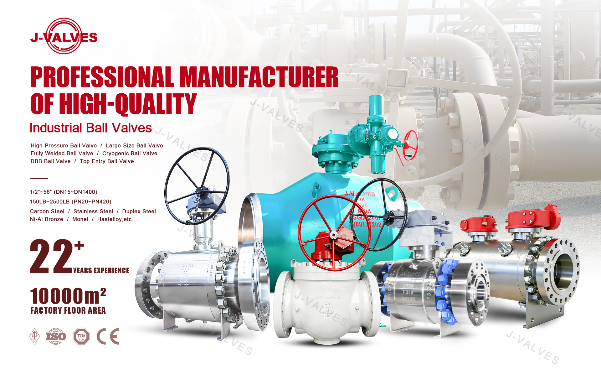
J-VALVES, a distinguished professional ball valve manufacturer rooted in China, takes pride in its extensive product portfolio. Our offerings span a wide range, including trunnion-mounted ball valves, floating ball valves, high-temperature ball valves, high-pressure ball valves, metal-sealed ball valves, ultra-low temperature ball valves, DBB ball valves, Three-way And Four-way Ball Valve, and fully welded ball valves. Each product is a testament to our commitment to precision engineering and reliable performance. Meticulously crafted, they are designed to not only meet but exceed the most stringent industrial demands, ensuring stable operation even under extreme conditions. This enables us to provide our clients with high-value services and makes our valves widely sought-after in industries.
Product Category
Contact Us


Pressure Class: ASME Class 150 / PN20, 19.6 bar at 38 C
Body Material: ASTM A351 CF3M (cast 316L), three-piece bolted
Ball Material CF3M hard chrome plated, CF8M optional
Stem: 316L, blow-out proof, anti-static, square drive
Seat Material: PTFE, RPTFE, PPL, PEEK
Service Temperature: -29 to +180 C (PTFE), +250 C (PPL), +260 C (PEEK)
Port Configuration: L-port diverter or T-port mixer / splitter
End Connection: Flanged RF, ASME B16.5 Class 150, 4 bolts
Mounting Pad: ISO 5211 F07 / F10, 17 mm square, integral high platform
Actuation: Direct mounted rack and pinion, electric quarter turn, or lever
Break Torque: 105 N.m L-port, 120 N.m T-port (PTFE, Class 150)
Flow Coefficient: Kv 230 m3/h L-port, 185 m3/h T-port
Design Standard: ASME B16.34, API 608, ISO 5211
Test Standard: API 598 / EN 12266-1, three-port seat test
Leakage Class: ISO 5208 rate A, soft seat
Surface Finish: Ra 3.2 um standard; Ra 0.8 um on request
Options: Solenoid, limit switch, filter regulator, manual override, PEEK seat, cavity drain
-
Q44F / Q45F
-
J-VALVES
A high platform three-way ball valve is a three-port ball valve whose body carries an integrally cast, raised mounting pad drilled to ISO 5211, so a pneumatic, electric or manual operator bolts straight onto the valve stem without a bracket or a coupling. The 3 inch (DN80) Class 150 version on this page is cast in ASTM A351 CF3M, the 316L grade, with a three-piece bolted body, an L-port or T-port ball and a pad that takes an F07 or F10 pattern.
The pad is the reason this valve exists as a separate product rather than a variant. A bracket and coupling assembly adds two mechanical joints between the actuator and the ball, increases the stack height by 60 to 120 mm, and has to be aligned by hand. A high platform removes both joints, keeps the actuator concentric with the stem by machining rather than by adjustment, and lets a manual lever be swapped for an actuator on an installed valve without opening the line. For a skid builder who fits actuators in his own shop, or a plant that standardises on one actuator model across a size range, that is the whole argument.
This page covers the ISO 5211 dimensions and what they do not tell you, the direct-mount case measured against bracket mounting, the flange arithmetic that catches buyers on 3 inch valves, the difference between CF3M and CF8M on welded and chloride duty, the seat choice for clean-in-place service, and the mounting mistakes that damage pads and actuators.

Key facts at a glance
Item | Value for this valve |
|---|---|
Size | 3 inch / DN80 (range DN15 to DN300) |
Pressure class | Class 150 to ASME B16.5 (quoted as PN20 in metric catalogues) |
Body | ASTM A351 CF3M cast stainless (316L), three-piece bolted |
Ball | CF3M, hard chrome plated; CF8M optional |
Stem | 316L, blow-out proof, anti-static, square drive |
Mounting pad | ISO 5211 F07 / F10, 17 mm square, integral |
Seat | PTFE, RPTFE, PPL or PEEK |
Temperature | -29 to +180 °C on PTFE; +250 °C PPL; +260 °C PEEK |
Port | L-port (diverter) or T-port (mixer / splitter) |
Ends | Flanged raised face, ASME B16.5 Class 150, 4 bolts |
Actuation | Direct mounted rack and pinion, electric quarter-turn, or lever |
Standards | ASME B16.34, API 608, ISO 5211, API 598 / EN 12266-1 |
What the ISO 5211 pad actually specifies
ISO 5211 fixes four things at the interface: the bolt circle diameter, the number and thread of the bolts, the stem square or key size, and the height of the stem above the pad face. It does not fix the pad's external shape, its wall thickness, or how much bending moment it can take — and those are the numbers that decide whether a 6 kg actuator survives ten years of water hammer on a cast pad.
Pad size | Bolt circle | Bolting | Square drive range | Typical valve size |
|---|---|---|---|---|
F04 | 42 mm | 4 × M5 | 9 to 11 mm | DN8 to DN25 |
F05 | 50 mm | 4 × M6 | 11 to 14 mm | DN15 to DN50 |
F07 | 70 mm | 4 × M8 | 14 to 17 mm | DN32 to DN80 |
F10 | 102 mm | 4 × M10 | 17 to 22 mm | DN65 to DN150 |
F12 | 125 mm | 4 × M12 | 22 to 27 mm | DN125 to DN250 |
F14 | 140 mm | 4 × M16 | 27 to 36 mm | DN200 to DN400 |
A DN80 valve normally carries F07 with a 17 mm square, and some makers offer F10 on the same body so a larger actuator can be fitted without changing the valve. Ask for the pad drawing, not just the pad size. The pad drawing shows the stem height above the pad face, and that number decides whether the actuator's drive boss seats fully on the square or bottoms out before the flange faces touch. A stem that is 3 mm too long holds the actuator flange off the pad, so the bolts clamp nothing and the joint works loose within a month.
The stem square also has to be long enough. As a rule the engagement should be at least 1.5 times the square size, so a 17 mm square needs about 25 mm of engagement. This is why a high platform pad is machined on a raised boss rather than sunk into the body: the boss gives the engagement length without putting the actuator inside the insulation envelope.
Direct mount against bracket mount
The bracket and coupling arrangement is not wrong; it is simply worse on six counts, and the six add up to a maintenance cost that shows up two years later rather than at the purchase order.
Point | Bracket and coupling | Integral high platform |
|---|---|---|
Mechanical joints between actuator and ball | Two extra: coupling to stem, coupling to actuator boss | None; the actuator boss sits directly on the stem square |
Concentricity | Set by hand during alignment, and it drifts | Set by machining, and it repeats |
Backlash at the switches | 0.5 to 2° lost in two splined joints | Effectively zero |
Stack height added | 60 to 120 mm | 0 |
Corrosion sites | Two carbon steel parts in a wet plant room | None added |
Actuator swap time | Realign and re-set the switches, 1 to 2 hours | Four bolts, 15 minutes, switches unchanged |
The switch point matters more than it looks. A spring-return actuator on a T-port ball has to hold position within a degree or two for the port to seal properly, and a coupling with 2° of lash makes the mechanical limit switch trip early or late depending on which direction the valve last moved. On a duty where the control system uses the switch as proof of port position, that lash becomes an intermittent alarm that nobody can reproduce.
The flange question on a 3 inch valve
A 3 inch valve sits on the one size where the metric and imperial flange systems diverge most, and the label "PN20" is where the confusion starts. PN20 is a 20 bar metric designation, but it is not an EN 1092-1 rating for DN80, and in Chinese export practice a PN20 flange is normally drilled to ASME B16.5 Class 150 dimensions. Class 150 at 3 inch is a four-bolt flange. A genuine DN80 PN16 flange is an eight-bolt flange on a different bolt circle.
Standard | OD | Bolt circle | Bolting | Thickness |
|---|---|---|---|---|
ASME B16.5 Class 150, 3 inch | 190.5 mm | 152.4 mm | 4 × Ø19 | 23.9 mm |
EN 1092-1 PN16, DN80 | 200 mm | 160 mm | 8 × Ø18 | 20 mm |
A valve sold as "3 inch DN80 PN20 Class 150LB" cannot be all three. It is one physical flange, and the safest reading of the trade label is Class 150 drilling, four bolts, 190.5 mm bolt circle. If the counter-flange in the plant is a DN80 PN16 with eight bolts, the valve will not fit, and the mistake is only discovered on site because both are called "3 inch". Confirm the drilling on the purchase order with a sketch, and keep the metric and imperial labels out of the same line.
Face-to-face is the second trap. Class 150 valves follow ASME B16.10; PN valves follow EN 558 series 1. The two are close in the small sizes and diverge in the large ones, and a spool piece cut to the wrong length has no adjustment. Quote the standard and the dimension, not just "standard face to face".
CF3M, CF8M and CF8: the choice that is usually made by habit
CF3M is the cast 316L grade to ASTM A351: 17 to 21 % chromium, 9 to 13 % nickel, 2 to 3 % molybdenum and 0.03 % maximum carbon. The molybdenum is what buys pitting and crevice corrosion resistance in chloride service, and the low carbon is what keeps the heat-affected zone from sensitising when the valve is welded into a line or when the body itself is repaired by welding.
Grade | Carbon | Molybdenum | PREN | Where it is the right answer |
|---|---|---|---|---|
CF8 (304) | 0.08 max | none | about 18 to 19 | Potable water, HVAC water, weak chemicals, dry air. Cheapest correct choice |
CF8M (316) | 0.08 max | 2 to 3 % | about 24 to 26 | Chloride water, dilute acids, coastal atmosphere, general chemical duty |
CF3M (316L) | 0.03 max | 2 to 3 % | about 24 to 26 | As CF8M plus welded joints, hot chloride, clean-in-place, pharmaceutical and food |
PREN is the pitting resistance equivalent number, calculated as Cr + 3.3 Mo + 16 N. The gap between 18 and 25 is the difference between a valve that pits in a brackish cooling line and one that does not. It is a rough index rather than a guarantee, but it is the fastest way to explain to a buyer why 304 is not a substitute for 316L in a coastal plant.
On a three-piece body the carbon content matters more than on a one-piece casting, because the end caps are machined and may be weld-repaired. A 0.08 % carbon grade that is welded and then held at 450 to 850 °C precipitates chromium carbide at the grain boundaries and leaves the adjacent metal short of chromium. That is sensitisation, and it shows up as knife-line attack along the weld after a year in a chloride line. CF3M does not sensitise in the same way, which is why hygienic and welded duty should never be quoted in CF8.
Where CF8 is genuinely better is cost and nothing else. On a plant room chilled water line at 12 °C with no chlorides, CF8 lasts as long as CF3M and costs 15 to 25 % less. Paying for molybdenum in that duty is a donation to the foundry.
Three-piece body: the reason this valve is serviceable
The body is three castings — two end caps and a centre section — bolted together with the seats and ball captured between them. Two consequences follow, and both are practical rather than theoretical.
First, the valve can be rebuilt in place. Loosen one flange, unbolt the caps, and the ball, seats and stem come out with the body still hanging in the pipe run. On a skid with 40 valves in a row, or a valve at the bottom of a pit, that is the difference between a two-hour job and a two-day one. Second, the seat compression is set by the joint, not by a threaded adjuster, so a rebuild restores the original seat load rather than a guess at it. Use a new body gasket and follow the bolt torque sequence.
What a three-piece body does not give you is a smaller leak path. There are two body joints per valve, each with its own gasket, and each is a potential weeper on a thermal cycling line. On steam or on a line that goes from ambient to 150 °C daily, specify a graphite or spiral-wound body gasket rather than a PTFE one.
Port configuration, flow and the 180° question
An L-port ball has two openings 90° apart and diverts flow from one outlet to the other. A T-port ball has a tee passage, connects all three ports at mid-travel, and needs 180° of rotation to reach the fourth position. On a direct-mounted valve this is easy to change later, because the actuator can be swapped for a 180° unit without touching the body; on a bracketed valve the same change means a new bracket, a new coupling and a new alignment.
Port | Kv at DN80 (m³/h) | Break torque, PTFE, Class 150 | Actuator output needed (1.3) |
|---|---|---|---|
L-port | 230 | 105 N·m | 137 N·m |
T-port | 185 | 120 N·m | 156 N·m |
The T-port carries two sealing lands and a split passage, so it costs 20 % of flow capacity and about 15 % more torque for the same bore. Neither number is large, but both have to be used when the actuator is chosen: a unit sized on the L-port figure will be marginal on the T-port valve of the same size. Nominal figures; the certified curve for the valve supplied goes on the flow test certificate.

Mounting practice: six ways to damage a pad
A high platform is a machined boss on a casting, and a casting is not a steel block. These are the failures we see on returned assemblies.
Over-torqued pad bolts. An M8 bolt at 40 N·m instead of 20 to 25 N·m will crack a cast pad at the hole or pull a thread. Use the actuator maker's figure and a torque wrench, not a rattle gun.
Mismatched pad and actuator. An F10 actuator on an F07 pad with an adapter plate is a bracket in disguise, and it reintroduces the eccentricity the platform was bought to remove.
Short stem engagement. A stem square that engages 8 mm of a 17 mm drive rounds off under torque, usually at the worst moment. Check engagement before the bolts are tightened.
Heat at the pad. At 180 °C media the pad can sit at 120 to 150 °C, which is above the limit of standard nitrile seals in the actuator. Specify viton, or fit a stand-off, above 150 °C.
Condensation in the actuator. A cold water valve in a humid plant room pulls water into the cylinder through the breather. IP67 housing plus a drain plug, or a desiccant breather, is cheaper than a replacement cylinder.
Bending from the line. A 5 kg actuator on a 3 inch valve is a cantilever, and unsupported pipe transmits its vibration straight into the pad. Support the pipe within 500 mm of the valve on both sides.
Clean service: what changes for CIP and SIP
The CF3M body and the three-piece construction make this valve a candidate for hygienic duty, but three details decide whether it actually performs there.
Seat temperature under steam. Clean-in-place runs at 80 to 90 °C with 1 to 2 % caustic, which PTFE handles comfortably. Sterilise-in-place at 121 to 140 °C saturated steam is a different matter: PTFE is inside its temperature range but permeates and cold-flows under repeated steam cycling, and the seat takes a set. Specify PEEK, or a PTFE seat with a metal backing ring, for repeated SIP.
Crevices and drainability. A three-way body has a branch that can trap liquid when the ball blocks it. Mount the valve so the branch drains, or specify a cavity drain plug, and confirm the internal finish. A Ra 0.8 µm wetted surface is the usual hygienic request; the standard machined finish is closer to Ra 3.2 µm.
Elastomer and gasket compatibility. Caustic at 90 °C attacks some nitrile grades, and the body gaskets see the same fluid as the seats. Ask for the gasket material in writing, not just the seat.
Testing and documentation
The valve is shell tested at 1.5 times the Class 150 rating, which is 29.4 bar, for a minimum of 60 seconds, then seat tested at 1.1 times rating, 21.6 bar, on each of the three ports with air under water. Soft-seated acceptance is ISO 5208 rate A, no visible leakage. Torque is measured at test pressure and recorded by serial number, and the actuator is checked for five full cycles at the minimum site air pressure rather than at the works supply.
Documentation: EN 10204 3.1 certificate for body, ball and stem with the heat numbers; pressure and seat test report; torque record; ISO 5211 pad drawing with the stem height; dimensional drawing. For hygienic duty, an elastomer declaration and a surface finish report. For welded installation, the intergranular corrosion test to ASTM A262 Practice E is available on request, and it is the certificate that actually proves the CF3M claim.

Installation checklist
Confirm the flange drilling against the counter-flange before the valve leaves the store: four bolts at 152.4 mm, or eight at 160 mm.
Check the pad and the actuator patterns match, and that no adapter plate is needed.
Clean the pad face and the stem square; grit under the boss holds the flange off the pad.
Torque the pad bolts to the actuator maker's figure in a cross pattern.
Set the open and closed cams on the actual port positions, then verify with flow, not with the indicator.
Cycle the valve five times on site air before handing over.
Leave the manual override engaged in the safe port position during commissioning.
Do not insulate across the pad; insulate up to it.
How to specify a high platform three-way ball valve
Give the size, the flange standard and drilling, the port configuration and whether the actuator must reach 180°, the body grade with the medium and its chloride content, the seat material with the cleaning regime, the flow and allowable pressure drop, the pad size required by the actuator you intend to fit, the fail position as a port pair, and the documentation package. If the valve is going into a skid that is assembled elsewhere, add the actuator model and the stem height, because that is the interface where two suppliers blame each other.
High platform three-way ball valve FAQ
What does "high platform" mean on a ball valve?
It means the body has an integrally cast and machined boss, drilled to ISO 5211, that raises the mounting face above the stem gland so an actuator bolts directly onto the stem square. No bracket or coupling is needed. The result is a shorter stack, no alignment step and no backlash between the actuator and the ball.
Is a high platform the same as direct mount?
In practice, yes. Direct mount is the function and high platform is the geometry that makes it possible. A valve can be direct mountable only if the pad is drilled to the actuator's ISO 5211 pattern and the stem height matches; a valve with a pad but the wrong stem height still needs a spacer.
What is the difference between 3 inch Class 150 and DN80 PN16 flanges?
The drilling. A 3 inch Class 150 flange is 190.5 mm outside diameter on a 152.4 mm bolt circle with four Ø19 bolts. A DN80 PN16 flange is 200 mm on a 160 mm circle with eight Ø18 bolts. They are both called "3 inch" in trade language and they do not bolt together. Quote the standard and the drilling.
Why CF3M instead of CF8M?
CF3M is the low-carbon 316L casting, 0.03 % carbon against 0.08 % for CF8M. Both have 2 to 3 % molybdenum and similar pitting resistance, but CF3M does not sensitise when welded, which matters on weld-repaired bodies, welded end connections and hygienic duty. On a bolted valve in clean water the difference is small; on anything welded it is decisive.
Can the actuator be changed without removing the valve from the line?
Yes, that is the point of the pad. Isolate and depressurise the line, unscrew the four pad bolts, lift the actuator off the stem square and fit the replacement. The switches and the stroke settings are disturbed, so the cams have to be re-set, but the body and the pipe stay where they are.
Which seat material is used for steam sterilisation at 121 °C?
PEEK, or a PTFE seat with a metal backing ring. PTFE is inside its temperature range at 121 °C but permeates and cold-flows under repeated steam cycling, so the seat takes a permanent set and leaks on the second or third cycle. PPL at +250 °C is an alternative where the higher torque can be accommodated.
How much torque does a 3 inch three-way ball valve need?
About 105 N·m break-to-open on an L-port with PTFE seats at full Class 150 differential, and about 120 N·m on a T-port. Apply 1.3 for a double-acting actuator and 1.5 for spring return. The figure has to come from the test sheet, because seat material, medium and cycling history all move it.
Does the pad limit the size of actuator that can be fitted?
The pad limits the bolt pattern and the bending moment, not the torque. An F10 pad can carry a larger cylinder than an F07, and a cast boss has a finite strength in bending, so a heavy actuator on a small pad needs a support or a stand-off. Ask for the pad's allowable moment if the actuator is over about 8 kg.
J-VALVES casts, machines and tests three-way ball valves in Wenzhou, Zhejiang, from DN15 to DN300 in CF8, CF8M and CF3M, with L-port and T-port balls, integral ISO 5211 pads from F04 to F12, and PTFE, RPTFE, PPL, PEEK or metal seats. Pad drawings with the stem height are issued before machining, so the actuator interface is settled before either supplier cuts metal. Send the medium, the flange drilling and the actuator model, and the pad, stem square and fail position will be confirmed in writing.
Related: pneumatic three-way ball valve, 4 inch PN16 CF8 for actuated water and HVAC duty, and the three-way ball valve range for the full size and material matrix.
Hot Products


News
Ball Valves in A Kraft Pulp Mill: Black Liquor, Green Liquor And The Cost of Choosing The Alloy by Habit
White liquor at pH 14 cracks carbon steel welds, black liquor sets solid below 100 C, green liquor dregs grind seats: alloy choice and torque in a kraft mill.
Read More
Slug Flow And Ball Valves: What Actually Arrives At The Seat
A slug is liquid mass with momentum, not a pressure spike. What changes at the seat, in the cavity and at the actuator when liquid reaches a ball valve.
Read More
Ball Valves in Direct Lithium Extraction: PH 1 Eluate, Gypsum Scale And 438,000 Cycles in Twenty-Five Years
Direct lithium extraction swings valves from pH 1 eluate to pH 12 caustic, 48 column switches a day and gypsum scale. Materials, seats and torque.
Read More
Ball Valves in Geothermal Brine: Silica Scale, Chloride Cracking And The Cooling Trap
Why geothermal brine destroys ball valves: retrograde silica scale, calcite at the flash point, chloride cracking above 60 C and the 250 C seat limit.
Read More