


CHINA J-VALVES Offers Various High-quality I ndustrial Ball Valves
J-VALVES, a distinguished professional ball valve manufacturer rooted in China, takes pride in its extensive product portfolio. Our offerings span a wide range, including trunnion-mounted ball valves, floating ball valves, high-temperature ball valves, high-pressure ball valves, metal-sealed ball valves, ultra-low temperature ball valves, DBB ball valves, Three-way And Four-way Ball Valve, and fully welded ball valves. Each product is a testament to our commitment to precision engineering and reliable performance. Meticulously crafted, they are designed to not only meet but exceed the most stringent industrial demands, ensuring stable operation even under extreme conditions. This enables us to provide our clients with high-value services and makes our valves widely sought-after in industries.
Product Category
Contact Us


-
J-VALVES-Q667F
-
J-VALVES
Overview of the J-VALVES fully welded trunnion mounted ball valve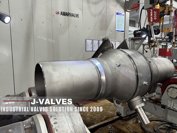
This is the page the rest of the family is cut from. Two inch to sixty inch, Class 150 to 900, a forged shell welded into one piece, a ball on trunnions, and butt weld ends with an optional flanged transition. The variants on the same site, with sleeves, with an extended stem, with electric or pneumatic drives, are this valve with one feature changed.
The word welded is doing more work on this page than the rest of the description put together. It removes the body joint, the gasket and the studs, which is what the page sells. It also removes the ability to open the valve, which is what the page does not say: with no joint there is no access, and with no access a failed seat or a leaking seam is not a part to be replaced but a weld to be made.
So this page is about the consequence rather than the feature. What can still be repaired on a valve that cannot be opened, what a repair weld requires before and after it is made, and where the end of the road is.
Design and Construction
The shell is a forged pipe section closed by two forged ends, welded circumferentially and radiographed before the bore is finished. The ball sits between two seats on an upper and a lower trunnion, so the pressure load goes into the bearings and the seats seal. The stem leaves the body through graphite packing, and the cavity is reached through a drain and two seat injection ports.
Nothing on that list can be reached from outside except through a port or the top. The top is a bolted flange carrying the drive, which means the stem packing can be adjusted and the drive can be changed, and beyond that the only access to the inside of the valve is the injection ports and the drain.
The photograph is worth reading as an inventory, because that inventory is what a repair plan has to work with. Two or four circumferential seams depending on the end configuration, one bolted top flange, one drain and two injection ports. Every one of those is a potential leak path and every one of them is also the only way to touch the inside of the valve.
That end view is the clearest statement of what a welded valve is. There is a machined face, a stepped bore and no bolt holes anywhere on it. The pipe is welded to that face, and once it is welded the valve is part of the line rather than an item in it.

Repair on a Welded Body
The repairable list is short and it is worth knowing before anything goes wrong. The packing can be adjusted or replaced from the top. The drive can be changed. A weeping seat can often be brought back with sealant through the injection port, and a cavity that will not hold can be proved through the drain. Those four cover most of what actually fails in service.
| What Failed | Can It Be Repaired in Place | What Has to Follow |
|---|---|---|
| Stem packing | Yes, from the top flange | Gland adjustment and a leak check |
| Seat leakage | Usually, by injection | Sealant volume, and a cavity test afterwards |
| Drain or injection plug | Yes, if the thread is sound | New plug, and a pressure test at the port |
| Body seam leak | Only by welding | Procedure, excavation, hardness check, full retest |
| Corrosion pit through the wall | Only by welding, if the wall allows | Wall measurement first, then a repair procedure |
| Crack in a seam or its heat affected zone | Rarely | Assessment against minimum wall, often a replacement |
Anything below the fourth row is a weld, and a weld on a pressure boundary is a different kind of job from a gasket. It needs a procedure qualified to ASME IX for that steel and that thickness, an excavation through the wall to sound metal with a profile the procedure allows, a preheat if the steel and the thickness call for one, and a consumable matched to the body.
The acceptance is the part that is usually underestimated. A repair weld on a valve that was radiographed at build has to be examined again, by radiography or by another method agreed with the buyer, and the valve has to be pressure tested again as a shell. A repair that is welded, coated and put back without a retest is a repair that has moved the risk rather than removed it.
There is also a limit on how many times a shell can be repaired. Each repair puts heat into the same region, and each heat cycle changes the microstructure a little. A seam that has been repaired twice is a seam that should be assessed rather than repaired a third time, and a crack that keeps returning in the same place is telling you something about the design or the line, not about the weld.
Technical Specifications
The table is the build from the specification block, with the range reconciled. The page carries two range blocks that disagree: the specification says Class 150 to 900, and a features block lower down says 150 to 2500. Only one of them can be true for a sixty inch welded body, and the narrower one is the one that matches the flange standard.
| Item | Value |
|---|---|
| Size range | 2 inch to 60 inch, DN 50 to DN 1500 |
| Pressure class | Class 150 to Class 900, PN 20 to PN 150 |
| Temperature | Minus 29 to plus 425 Celsius, carbon steel body |
| Body | Forged A105, or A350 LF2, F304, F316, F51, F53, or API 5L line pipe steel |
| Body joints | None, welded shell |
| Ball | F304, F316, F51 or F53, with tungsten carbide coating or hardfacing |
| Ball support | Upper and lower trunnion |
| Stem | F6a, F304, F316, 17-4PH or nickel alloy 718 |
| Stem seal | Graphite packing, in the body |
| Seat | RPTFE as standard, a higher temperature polymer, or metal with graphite |
| Seat design | Single piston effect or double piston effect |
| Drain | At the lowest point of the cavity |
| Injection ports | One at each seat |
| Ends | Butt weld to ASME B16.25, flanged transition optional |
| Top connection | Bolted pad for gear, electric, pneumatic or hydraulic drive |
| Support | Welded saddle feet for large sizes |
| Design | API 6D and ASME B16.34 |
| Test | API 6D and API 598 |
Three rows are the ones a repair plan needs. The body joints row says none, which is why the fourth row of the repair table exists at all. The injection port row says one per seat, which is the only non destructive route to a weeping seat. And the support row is easy to overlook: the feet are welded to the shell, so they are part of the pressure boundary's neighbourhood and a repair near them has to account for the restraint they impose.
The two range blocks are worth one more sentence because they are a symptom. A features block that says 150 to 2500 under a specification that says 150 to 900, alongside a body described as two to three piece on a welded valve, is a block that was written for the family and pasted onto the page. It should be corrected rather than reconciled, because a buyer who reads only the features block will ask for a valve that does not exist.
Standards and Compliance
API 6D governs the valve and ASME B16.34 the wall and the ratings, and neither of them describes a repair. That is not an oversight: a valve standard covers a new valve, and a repair is a procedure qualified against the welding standard and accepted against the original test.
| Document | What It Fixes | What It Leaves Open |
|---|---|---|
| API 6D | Classes, test, marking, cavity relief | Repair of a valve in service |
| ASME B16.34 | Minimum wall and ratings | How much wall a repair may remove |
| ASME IX | The welding procedure and its qualification | Whether the repair is acceptable |
| API 598 | The shell and seat test | Whether the repair is retested at all |
| NACE MR0175 | Hardness limits for sour service | Hardness of a weld made in the field |
| ASME B16.25 | The weld end profile | The line pipe it meets |
The wall question is the one that decides most repairs. ASME B16.34 gives a minimum wall for the class and size, and a repair that excavates a pit removes material from a wall that was already close to that minimum at the thinnest point. The measurement comes before the procedure, not after, because a pit that leaves less than the minimum cannot be welded back into compliance whatever the procedure says.
For sour service there is a second acceptance that is easy to miss. NACE MR0175 limits hardness in the weld and in the heat affected zone, and a repair made in the field with a procedure qualified only for strength will not necessarily meet it. The hardness survey after the repair is what closes that gap, and it is the item most often left out of a repair instruction.
Manufacturing Process
The shell is welded in a fixed sequence. The two ends are machined with the weld preparation, aligned to the pipe section, tacked and welded, and the assembly is radiographed before any bore is cut. Where the wall and the steel call for it the shell is stress relieved, and only then is it machined for the ball, the seats, the stem bore and the ports.
That sequence is why a repair is a different job. In the shop the weld is made on an open shell, from both sides where the access allows, with the part free to move and the heat going into a piece that has no seats in it. In the field the weld is made from one side, into a shell that is bolted to a pipeline and full of machined surfaces that must not be distorted.
The seat pockets are the parts at risk. They are machined to a tolerance that a seat ring has to sit in, and heat put into the shell near a pocket can move it enough to pinch a seat. That is the reason a repair near the body centre is treated more cautiously than a repair at a sleeve or a flange transition, where the geometry is simpler and further from the sealing surfaces.
Marking and testing close the build. The shell is hydro tested, the seats are tested in the direction each is loaded, the ports are plugged and tested, and the coating is applied with the ends masked so that the weld preparations stay bare.

Quality Control and Testing
Every shell seam is radiographed and the shell and seat tests follow to API 6D and API 598. On a welded body the radiography is not a sample; it is the only examination of the joints that will never be seen again, and a film that is missing is a joint with no record.
The port plugs are tested separately, because they are small and easy to leave out. A drain plug that weeps is a leak that appears months after installation, at the bottom of a valve, in a place where somebody has to dig.
For a repair, the examination sequence is different and it runs in the other direction. The excavation is checked by penetrant or magnetic particle before welding, the finished weld is checked by the method agreed with the buyer, the hardness is surveyed if the service requires it, and the shell test is repeated. A repair that skips the first step is a repair made into a defect that was not fully removed.

Applications and Industry Service
The first use is a section isolator on a transmission line, where a welded body is chosen because there is no joint to leak and no gasket to replace, and where the valve may sit in the ground for decades with nothing done to it.
The second use is a station or a manifold, where the same valve is above ground and the drive matters more than the body. That is where the variants come in: electric for a site with power, pneumatic for a site with instrument air, gas hydraulic for a site with neither, and a sleeve where the line steel and the body steel do not match.
The valve is the wrong choice where the service is expected to need seat access, because a welded body has none beyond the injection ports; and where the line is small enough that a two or three piece body costs less and can be opened. It is also the wrong choice where a repair is likely, since every repair on this valve is a weld with a procedure and a retest behind it.

Installation, Operation and Maintenance
Installation is a butt weld at each end, made with the valve open and the bore protected, and with the body supported on its own feet rather than hung from the pipe. A large welded valve is heavy, and a shell that is carrying its own weight plus the actuator is a shell with a bending stress in it that no rating table accounts for.
Alignment before the root is the whole job on a welded valve. There is no flange to absorb a mismatch, so the pipe ends have to be true to the bore, and a valve pulled into line by its own weld keeps that preload for life.
Maintenance is deliberately limited: the packing at the top, the drive on its pad, the injection ports and the drain. The plan should say what happens when injection stops working, because at that point the options are a weld or a replacement, and knowing which before the event is the difference between a planned shutdown and an unplanned one.
How to Specify and Order
The lines below are the ones the page leaves open, and the first two decide what can be done to the valve after it is installed.
| Line on the Order | What to Write | Why It Matters |
|---|---|---|
| Size and class | 2 to 60 inch, Class 150 to 900 | The features block says 2500 and does not apply |
| End configuration | Butt weld, with or without a transition | A transition moves a weld into the shop |
| Body steel | A105, LF2, duplex, or line pipe steel | The repair procedure follows the steel |
| Seat | Polymer or metal, with the temperature | The seat is the part most likely to need injection |
| Injection ports | One per seat, and where they terminate | They are the only non destructive access |
| Support | Saddle feet, and the foundation they sit on | The shell should not carry the assembly weight |
| Repair basis | The welding standard and the retest to be applied | A repair without a retest moves the risk |
| Marking and records | Heat code, radiography and test reports | The only history the valve will ever have |
Read as a whole, the page describes a valve that trades access for tightness and then lives with the trade. The shell will not open, the seats can be reached only by injection, and anything worse than a seat is a weld with a procedure behind it. That is a good bargain on a buried transmission line and a poor one on a valve that has to be rebuilt every few years, and the page is more useful once it says which is which.
FAQ
Q: Can a welded valve be repaired without cutting it out of the line?
A: Partly. The packing, the drive, the drain plug and the seat injection ports can all be worked from outside, and a weeping seat can often be brought back by injecting sealant. Anything that has to be welded, such as a seam leak, a corroded pit or a damaged port thread, is a weld on a pressure boundary, and it needs a qualified procedure and a full retest afterwards.
Q: What has to happen before a repair weld is made?
A: The wall has to be measured, the defect excavated to sound metal, and the excavation checked before welding. Then a procedure qualified to ASME IX for that steel and thickness is applied, with the preheat and the consumable it calls for. After welding the joint is examined again and the shell is retested, which is the step that turns a patch into a repair.
Q: How many times can the same seam be repaired?
A: There is no number in the standard, and the honest answer is as few as possible. Each repair puts another heat cycle into the same region, and a crack that returns to the same place is telling you about the design or the line rather than about the weld. A seam repaired twice should be assessed against minimum wall before a third repair is attempted.
Q: Why does the page give two different class ranges?
A: Because a features block lower down was written for the family and pasted onto this page. The specification says Class 150 to 900 and the features block says 150 to 2500, and for a body welded up to sixty inch only the narrower range matches the flange standard. The same block also calls the body two to three piece, which a welded shell is not.
Q: What decides whether a welded valve is condemned rather than repaired?
A: The wall and the location. A pit that leaves less than the minimum wall for the class and size cannot be welded back into compliance, and a crack in a seam or its heat affected zone that keeps returning is a structural answer rather than a welding one. Both are decisions to be taken with the wall measurement and the inspection results in hand, not at the side of a trench.


Hot Products


News
Urea Plant Ball Valves: The Wetted Path Survives Only While Oxygen Is Being Fed To It
Carbamate at 150 bar and 185 C eats stainless 50 times faster once the passive film starves. The valve cavity is where the oxygen runs out first.
Read More
Stiction: What A Ball Valve Becomes When Nobody Turns It
A valve that stood closed for years has not worn out. The seat has bonded to the ball, and the first stroke is a step, not a ramp. What the trace shows.
Read More
Molten Salt Ball Valves: The Valve Works at 565 C And Dies at 219 C
Salt freezes at 220 C and decomposes at 565 C. Everything a molten salt ball valve does happens in that 345 kelvin gap, and the gap is not generous.
Read More
Direct Air Capture Ball Valves The Vacuum Side Runs The Seal Backwards, And Three Hundred Thousand Strokes Decide The Design
A solid sorbent DAC plant moves 1.3 million cubic metres of air per tonne of CO2, then asks a DN50 ball valve to hold 0.9 bar from the wrong side.
Read More